Efficient optical path folding by using multiple total internal reflections in a microcavity
Abstract
We propose using an asymmetric resonant microcavity for the efficient generation of an optical path that is much longer than the diameter of the cavity. The path is formed along a star polygonal periodic orbit within the cavity, which is stable and confined by total internal reflection. We fabricated a semiconductor device based on this idea with an average diameter of 0.3 mm, and achieved a path length of 2.79 mm experimentally.
Asymmetric resonant cavities (ARCs) such as deformed disks and deformed spheres were proposed to make it possible to extract directional emissions while maintaining relatively high quality factors [1]. The effects of deformations on resonant mode characteristics have been studied by using the concepts and techniques of the quantum/wave chaos theory, and the idea of using cavity shape as a design parameter for controlling emission characteristics [2] has now been well established [3], with a representative achievement being a uni-directional emission deformed microdisk [4].
An interesting but less explored feature of ARCs is that they can generate long optical paths by using multiple reflections at cavity interfaces. This feature was demonstrated for a macroscopic (i.e., cm-size) deformed sphere made of copper with the aim of using it for gas sensing [5, 6, 7], where a long optical path is important for increasing the sensitivity. In that work, it was reported that a three-dimensional ARC with a diameter of 5.24 cm can achieve a path length up to 6.0 m. The idea itself of generating a long optical path by multiple reflections can be found in traditional gas sensing cavities consisting of multiple mirrors such as White cells [8] and Herriott cells [9], where the careful alignment of mirrors is necessary for generating a desired optical path. An advantage of using ARCs for long path generation is that they are alignment-free and suitable for miniaturization.
In addition to gas sensing, there are many applications where long optical paths are necessary or desirable, e.g. optical delay lines [10], optical gyroscopes [11], laser frequency stabilization [12], and laser chaos generation [13]. If there is no device size limitation, optical fibers would provide solutions in most cases. However, for micro-scale devices where the use of optical fibers is irrelevant, the idea of ARCs appears to be a promising option. For instance, recently, the chaotic output from a semiconductor laser with delayed optical feedback has been utilized for Gbps-speed physical random bit generation [14], and efforts have been made to reduce the device size by photonic integration [15, 16, 17]. To ensure good quality of randomness, an external cavity at least about 3 mm long is indispensable for delay generation [17], which currently is an obstacle for further miniaturization. The use of ARCs has the potential to provide a breakthrough as regards this problem [18].
In this Letter, we propose the use of a deformed annular microdisk for efficiently achieving a path length much longer than the device’s diameter, while suppressing refraction losses by total internal reflection (TIR). We fabricate a semiconductor device based on this idea, and show that a path length of 2.79 mm can be achieved by the device, whose average diameter is 0.3 mm. In previous studies [5, 6, 7], a long path was attributed to a multi-reflected chaotic ray orbit. However, it is difficult to identify the responsible orbit and thus to predict a priori an optical path length (or equivalently a delay time). In contrast, here we systematically construct a stable periodic ray orbit within the cavity to obtain a long optical path, which enables us to predict the path length precisely. The work in Ref. [18] uses a two-dimensional microcavity with quasi-stadium shape to form such a stable periodic ray orbit, and light propagation along it was confirmed. However, most of the light intensity is lost through transmission, since the incident angles at the cavity interfaces are close to 0 degrees. A significant improvement demonstrated in the current work is that a stable ray orbit is reflected more times by a cavity interface, while all of the reflections are TIRs, so that the confinement is more efficient in terms of energy and space.
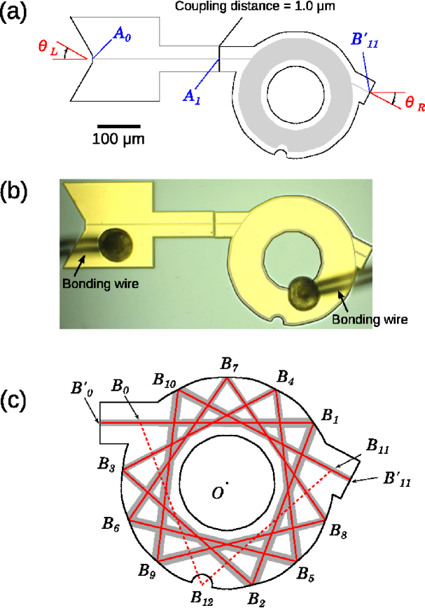
Figure 1 shows the geometry of our device, which consists of a quasi-stadium cavity (left) and a deformed annular cavity (right). Both cavities are pumped, but in this Letter, we consider the former to be a light source and the latter to be an external cavity (i.e., the pumping for the latter is set below the threshold). The quasi-stadium cavity has Fabry-Perot-type modes [19], while the deformed annular cavity has modes whose intensities localize along a ray orbit with a long path reflected by TIR (described below). With this design, the light emitted from the quasi-stadium cavity is coupled to the deformed annular cavity, amplified there, and then emitted. The light is emitted to the far field from the left facet of the quasi-stadium cavity and from the output port facet of the deformed annular cavity [see Fig. 1 (a)].
Here, we define the cavities more precisely: With the quasi-stadium cavity, modes are formed along the Fabry-Perot-type orbit connecting both ends and , whose distance is . The radii of curvature of the cavity boundaries at and are 600 and , respectively. These curvature values make the orbit stable [20], and corresponding resonant modes are given by Gaussian beams whose beam waist is at with a (half) width of .
The boundary of the deformed annular cavity is defined in the polar coordinates by , where for the outer boundary, while for the inner boundary. Here we fix the ratio as . When we consider this cavity as a closed billiard, it has a star polygonal periodic orbit with vertices. We use to denote the number of clockwise rotations around the origin for the ray propagation along the star polygonal orbit until it returns to the initial point (an example for and is shown in Fig. 1 (c)).
When setting the and values, we consider the two factors described below. (i) The total length of the star polygonal orbit is given by
| (1) |
As we are interested in generating as long a path as possible, it is desirable to set close to with as large a value as possible. Here, we also have to note that the distance between adjacent vertices of the star polygonal orbit (e.g., the arc ) needs to be much longer than a wavelength within the cavity, which limits the maximum value of . This is a condition imposed by the wave picture to guarantee that the wave propagates distinctly along the orbit. (ii) The incident angle at the cavity boundary is given by . Since we want to confine the orbit by TIR, we have the condition , where is the effective refractive index of the cavity, and we assume the cavity is surrounded by air. In this work, we fix , and assume that the cavity is made of GaAs (i.e., the wavelength in vacuum and ). To satisfy the above two conditions sufficiently, we choose and in the current work.
Next, we explain how we determine the value of the parameter . We open the deformed annular cavity so that it couples to the quasi-stadium cavity and to the far field. We attach an input port with length at the vertex and an output port with length at the vertex as shown in Fig. 1 (c). Then, we have a self-retracing periodic orbit connecting the facets of the input and output ports, and . To allow us to assume that the light propagates along this orbit in the form of Gaussian beams, we make the orbit linearly stable [21]. This condition is expressed by with being the monodromy matrix for the periodic orbit. To fulfill this condition, we chose , and , which yield . This trace value, together with the monodromy matrix elements, is directly related to the beam width of the Gaussian beam [21]. Denoting the coordinate along the star polygonal orbit as , and the coordinate perpendicular to it as , we can express the Gaussian beam profile as , where represents the beam width. In Fig. 1 (c), the area corresponding to the beam width (i.e., ) is shown in gray. The input port facet corresponds to the beam waist position, where the beam width is . This matches the beam waist size of the quasi-stadium cavity at the facet , . The coupling distance is set at . We also note that a half-circular scatterer with a radius is placed at the vertex to suppress the existence of undesired high-Q modes.
With the parameter values specified above, the total (one-way) length of the TIR-confined orbit is mm, which is 9.3 times longer than the diameter of the deformed annular cavity. Below, we demonstrate the existence of this long path experimentally. We fabricated a device with the cavity design described above by applying a reactive-ion-etching technique to a graded index separate confinement heterostructure single quantum well GaAs/AlGaAs structure grown by metal organic chemical vapor deposition. The layer structure and fabrication process are described in detail in Ref. [19]. For the quasi-stadium cavity, the electrode contact is formed only along the Fabry-Perot orbit with a narrow width of , while for the deformed annular cavity, the electrode contact is patterned to amplify the star polygonal orbit (the gray regions in Fig. 1 (a) represent the pumping regions). For the measurements, the device was operated in the continuous-wave mode at 25∘C. In what follows, we denote the injection current supplied to the quasi-stadium cavity as , and that supplied to the deformed annular cavity as , to indicate that the former cavity is a laser diode (LD), while the latter works as a semiconductor optical amplifier (SOA). The lasing threshold for the quasi-stadium cavity was , while that for the deformed annular cavity was . These thresholds were almost unchanged when the other cavity was pumped.
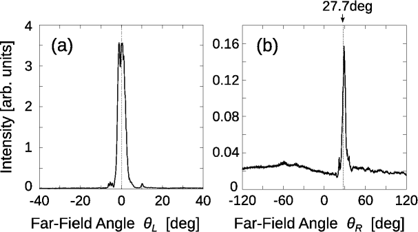
Figure 3 (a) and (b) show the measured far-field emission patterns obtained when (far above the threshold) and (just below the threshold) for the output from the quasi-stadium cavity [Fig. 3 (a)] and for the output from the deformed annular cavity [Fig. 3 (b)]. In Figs. 3 (a) and 3 (b), we can confirm the outputs from the quasi-stadium cavity and the deformed annular cavity, respectively. The position of the sharp peak in Fig. 3 (b), degrees is in good agreement with the angular direction of the output port of the deformed annular cavity. The far-field peak at around degrees was clearly observed when and were sufficiently large (for example, for , we could observe a sharp peak for ). Assuming that the far-field intensity is expressed as , we can evaluate the beam divergence as in Fig. 3 (b). This value is in good consistence with the beam waist size of the output beam at , , which yields . These results validate our assumption that the light propagates along the star polygonal orbit. As is observed in Figs. 3 (a) and (b), the output power from the facet is reduced by an order of magnitude as compared with the output power from the facet . We expect that this is caused by coupling losses at an air gap between the two facets and , and gain saturation in the deformed annular cavity.
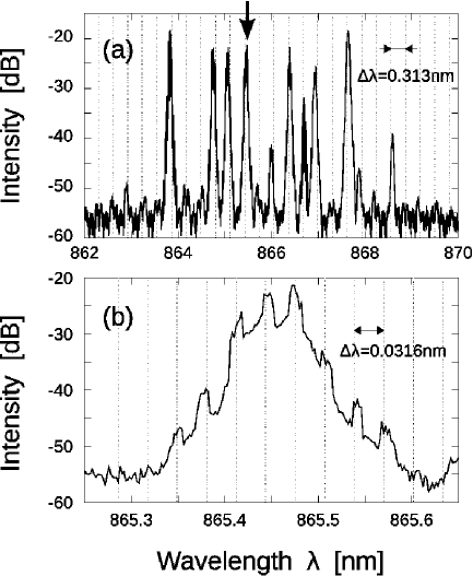
To further confirm the light propagation along the star polygonal orbit as well as the coupling of the two cavities, we measured the optical spectra for the emission from the quasi-stadium cavity (i.e., output from facet ). Figure 3 shows data for and , where Fig. 3 (a) is for the whole range, while Fig. 3 (b) is an enlarged image of the peak at nm in (a) (indicated by an arrow). In Fig. 3 (a), we can see a regular modal spacing of . This value corresponds well to the length of the quasi-stadium cavity, , which yields a longitudinal modal spacing of evaluated from the formula with the dispersion being (taken from Ref. [22]). Meanwhile, in Fig. 3 (b), we can observe a regular modal spacing of . For each peak in Fig. 3 (a), we could observe a similar substructure with the same modal spacing. This modal spacing value is explained by the path length of the coupled cavities, mm, which yields . These results mean that the characteristics of both quasi-stadium cavity and deformed annular cavity are manifested in the output of the quasi-stadium cavity laser. This validates our assumption regarding the coupling of the two cavities as well as the propagation of light along the star polygonal orbit.
In conclusion, we proposed the use of an asymmetric resonant microcavity for systematically constructing a long path corresponding to a stable star polygonal orbit that is confined by TIRs except for the input and output ports. We illustrated this idea by fabricating a device designed to generate a path length of 2.79 mm, which is 9.3 times longer than the cavity’s diameter. In principle, this factor can be greatly increased by optimizing the values of and . From the measured far-field emission patterns and optical spectra, we confirmed for the fabricated device that the light propagates along the designed long path. As reported in Ref. [17], a 3 mm-long external cavity is sufficient for generating chaotic oscillations suited for random bit generation. Since the extension of the path length over 3 mm is well within reach for our cavity design, we think that it can be used for realizing a compact random bit generator, where it is preferable to fabricate the cavity by a passive material and to apply high-reflection coating at the facet . We also expect that our idea would be of use for realizing a compact information processing device based on optical delay feedback [13]. As for the scalability, it appears to be of interest to couple multiple cavities to generate a much longer path while densely filling a two-dimensional area with them. This would allow us to make a path length proportional to where is the linear dimension of the footprint. These ideas will be examined in future works.
S. Sunada was supported in part by a Grant-in-Aid for Young Scientists (B) (Grant No.26790056) from the MEXT of Japan.
References
- [1] J. U. Nöckel and A. D. Stone. Nature, 385:45–47, 1997.
- [2] H. G. L. Schwefel, H. E. Tureci, A. D. Stone, and R. K. Chang. Optical Microcavities, chapter 9, pages 415–495. World Scientific, Singapore, 2005.
- [3] T. Harayama and S. Shinohara. Laser Photonics Rev., 5:247–271, 2011.
- [4] J. Wiersig, J. Unterhinninghofen, Q. Song, H. Cao, M. Hentschel, and S. Shinohara. Trends in Nano- and Micro-Cavities, chapter 4, pages 109–152. Bentham Science, Singapore, 2011.
- [5] E. Narimanov, J. Fan, and C. Gmachl. Technical Digest of Quantum, Electronics and Laser Science Conference, 1:421–423, 2005.
- [6] D. Qu, Z. Liu, and C. Gmachl. Appl. Phys. Lett., 93:014101, 2008.
- [7] D. Qu and C. Gmachl. Phys. Rev. A, 78:033824, 2008.
- [8] J. U. White. J. Opt. Soc. Am., 32:285, 1942.
- [9] D. R. Herriott and H. J. Schulte. Appl. Opt., 4:883, 1965.
- [10] H. Lee, T. Chen, J. Li, O. Painter, and K. J. Vahala. Nat. Comm., 3:369–373, 2012.
- [11] H. Lefèvre. The Fiber-Optic Gyroscope. Artech House, Boston, 1993.
- [12] H. Lee, M.-G. Suh, T. Chen, J. Li, S. A. Diddams, and K. J. Vahala. Nat. Comm., 4:2468, 2013.
- [13] M. C. Soriano, J. García-Ojalvo, C. R. Mirasso, and I. Fischer. Rev. Mod. Phys., 85:421–470, 2013.
- [14] A. Uchida, K. Amano, M. Inoue, K. Hirano, S. Naito, H. Someya, I. Oowada, T. Kurashige, M. Shiki, S. Yoshimori, K. Yoshimura, and P. Davis. Nat. Photon., 2:728–732, 2008.
- [15] A. Argyris, M. Hamacher, K. E. Chlouverakis, A. Bogris, and D. Syvridis. Phys. Rev. Lett., 100:194101, 2008.
- [16] T. Harayama, S. Sunada, K. Yoshimura, P. Davis, K. Tsuzuki, and A. Uchida. Phys. Rev. A, 83:031803(R), 2011.
- [17] R. Takahashi, Y. Akizawa, A. Uchida, T. Harayama, K. Tsuzuki, S. Sunada, K. Arai, K. Yoshimura, and P. Davis. Opt. Express, 22:11727–11740, 2014.
- [18] S. Sunada, T. Fukushima, S. Shinohara, T. Harayama, K. Arai, and M. Adachi. Appl. Phys. Lett., 104:241105, 2014.
- [19] T. Fukushima and T. Harayama. IEEE J. Sel. Top. Quantum Electron., 10:1039, 2004.
- [20] A. E. Siegman. Lasers. University Science Books, Mill Valley, CA, 1986.
- [21] H. E. Tureci, H. G. L. Schwefel, A. D. Stone, and E. E. Narimanov. Opt. Express, 10:752–776, 2002.
- [22] H. C. Casey Jr. and M. B. Panish. Heterostructure lasers. Academic Press, New York, 1978.