,
Long-time evolution of sequestered CO2 in porous media
Abstract
CO2 sequestration in subsurface reservoirs is important for limiting atmospheric CO2 concentrations. However, a complete physical picture able to predict the structure developing within the porous medium is lacking. We investigate theoretically reactive transport in the long-time evolution of carbon in the brine-rock environment. As CO2 is injected into a brine-rock environment, a carbonate-rich region is created amid brine. Within the carbonate-rich region minerals dissolve and migrate from regions of high concentration to low concentration, along with other dissolved carbonate species. This causes mineral precipitation at the interface between the two regions. We argue that precipitation in a small layer reduces diffusivity, and eventually causes mechanical trapping of the CO2. Consequently, only a small fraction of the CO2 is converted to solid mineral; the remainder either dissolves in water or is trapped in its original form. We also study the case of a pure CO2 bubble surrounded by brine and suggest a mechanism that may lead to a carbonate-encrusted bubble due to structural diffusion.
I Introduction
The sequestration of CO2 in geological formations is widely considered to be an important approach for mitigating the rise of atmospheric CO2 levels IPCC ; 07S ; 94BGP ; 03L ; 13SZ . Deep saline aquifers and gas fields are primarily chosen for storage IPCC ; 03L ; 03BA . Supercritical CO2 is injected into these porous media while displacing another fluid, brine 13SZ ; 07CBT . The CO2 then gradually dissolves; however, its long-term fate remains poorly understood 04BW . Here we address the long time scale and study theoretically the evolution of the CO2 after injection into the brine-rock system.
As the CO2 is injected into the brine-rock environment, it initially becomes trapped, either by a physical mechanism in the presence of low permeability rocks, or by retention as a separate phase in the pore space due to interfacial tension 04GBB . The disordered structure of the void spaces forces the injected fluid along certain paths that create regions, or bubbles, of the injected fluid amid regions of the defending fluid, and vice versa 86DW ; SA01 ; 83WW ; F88 . This process is known as invasion percolation when, as for the supercritical CO2, the invading fluid is non-wetting. For two immiscible fluids, the fluid configuration is often determined by the structure of the rock and by surface tension effects. Further, the two-phase system can become unstable when reactant particles migrate from one phase to the other and change the chemical composition of each phase 12RR ; 12NSYA . Within the high CO2 phase, minerals dissolve; diffusion causes minerals and carbonate species to migrate from high concentration to low concentration regions, and a fraction of them precipitates. In nature, this process can be seen in hot springs, when a bubble of oxygen emerges from photosynthetic cyanobacteria 91CRU ; 00FFMP . The high gradient of CO2 between the bubble and the surrounding water leads to loss of CO2 in the vicinity of the bubble, drives up the saturation level, and eventually a crust is created around the bubble. In general, mineral precipitation on a small boundary layer at the interface may lead to lower diffusivity and slower kinetics. In the carbon sequestration process, this may cause a mechanical trapping of the CO2 bubble and lower the solidification rate of the carbon minerals.
Here we develop theoretical understanding of this process of mechanical phase separation. We consider two scales: At the microscale, a single CO2 bubble is surrounded by brine in the void space of a porous medium. In this case, the reactions occur at the interface between the bubble and the brine, as the CO2 dissolves and reduces the pH in its vicinity. The macroscale averages over many such bubbles. In this case, a high concentration of the invaded CO2 changes the properties of a macroscopic region. The region becomes more acidic and no precipitation occurs unless the carbonate species migrate to a different region.
The paper begins by addressing the macroscale problem and the mathematical background of the reactive diffusion equation. We then study the mobility change in the fluid-rock system due to the precipitate minerals. Finally, we consider the microscale case of a single CO2 bubble amid brine and suggest a second mechanism that may also lead to separation and self-sealing.
II Macroscopic Reactive Transport
The injection of supercritical CO2 (scCO2) into a porous medium, initially occupied with another fluid, i.e., brine (salty water), generates two different regions in the system 12RR ; 13TRS . The first region is where the CO2 displaced most of the existing brine. In this region, the void space in the porous medium is filled with bubbles of CO2 and water saturated with carbonate species. The CO2 dissolves rapidly in the water to reach equilibrium which results in low pH, and also a high concentration of dissolved minerals 10LM ; 06KCHGKF . The second region is the intact brine-rock system, which is characterized by a low concentration of CO2 and higher pH. Fig. 1 depicts the complexity of the CO2-brine-rock system.

The existence of two phases and concentration gradients drives the components to migrate from one phase to another. As they diffuse, they react to reach a local equilibrium. Although pure scCO2 may be clogged due to mechanical or capillary trapping 09MK ; IPCC , in the presence of water it can dissolve into its ionic forms, i.e. bicarbonate and carbonic acid, until it reaches a local thermodynamical equilibrium ZW01 . These carbonate species may diffuse more easily through the brine. Within the high CO2 phase, minerals dissolve because of the acidic environment. They then migrate from high concentration to low concentration regions and a fraction of them precipitates. The evolution of each component can be described by the reactive diffusion equation
| (1) |
Here, the , , are the concentration of the CO2, HCO, CO, H+ and the mineral Ca2+, respectively. is the isotropic diffusion coefficient for the th component, and is the reaction rate defined by the carbonate system ZW01 ; 05DM and the dissolution and precipitation of calcite mineral. The latter can be expressed as 78PWP ; 89CGW ; 11D ,
| (2) |
where represents the density of precipitated calcite. The rate coefficient is defined by 89CGW
| (3) |
where is the reactive surface area, and k+i are the rate constants for the forward reactions. The saturation ratio 78PWP
| (4) |
is defined by the ion activity product divided by the solubility constant of calcite. Details of the reactions and the values of the reaction constants can be found in ref. 89CGW ; 08LSY . Whether the calcite will precipitate or dissolve is determined by the value of ; when dissolution occurs; when mineral precipitates, and when the system is at equilibrium.
III Numerical Simulation
In our model, we assume that there is no diffusion of the solid mineral as it nucleates and precipitates at the surface of the rock. Also, the capillary forces between the scCO2 and the water prevent the mixing between the two phases; therefore the diffusion constant of CO2 is also set to zero. Since the dissolution of calcite is considerably fast compared to dissolution of other minerals, we assume that, after injection, calcite dissolves quickly until it reaches equilibrium. Only new calcite that has been precipitated can be dissolved again. Thus, the reactive surface area is set to zero, as long as there is no previous precipitation of calcite.
We solve the reactive diffusion equations (Eqs. (1) and (2)) for each component using Galerkin finite elements method on quadratic triangular grid with a order Runge-Kutta integration scheme. The simulation starts when the carbonate system, the pH, and the dissolved calcium mineral are at local equilibrium in each phase. In region 1, the carbonate-rich brine-rock region (see Fig. 1), we set the pH to and the total dissolved inorganic carbon to mol/liter. In region 2, we set pH and the carbonate concentration at mol/liter. The simulation starts with the concentration of each one of the carbonate species and the dissolved calcium mineral at local equilibrium in each region.
We consider a carbonate-rich circular shape (region 1) is surrounded by brine (region 2). We find that the accumulation of calcite, shown in Fig. 2a, occurs on a small boundary layer close to the interface. The precipitation profile is approximated by the typical diffusion length , shown in Fig. 2b.
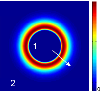
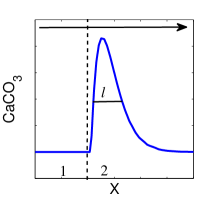
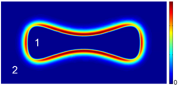
Fig. 3 shows qualitatively how the interface curvature alters the mineral precipitation. We find that the accumulated crust is highly dependent on the curvature of the interface due to the nature of a diffusion process through a curved interface 03BP ; negative curvature with respect to the inner bubble of the CO2 phase has maximum mineral precipitation at the interface.
Collectively, these results indicate that precipitation of mineral occurs on a small boundary layer at the interface and a carbonate crust, created in a small boundary layer, can lead to a mechanical separation of the two phases.
IV System Size Dependence
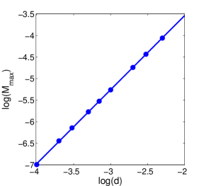
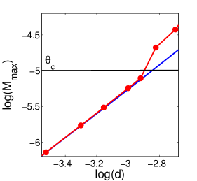
Mineral precipitation along the interface changes the porosity of the rock, decreases the effective diffusivity, and may clog existing voids 09MK ; IPCC . The decrease in the mobility of the ions in the solution could bring further solidification of minerals to a halt. Whether a pathway between pores will be clogged or not is highly dependent on the local density of the accumulated mineral, which depends also on the amount of the carbonate species, and the size and the shape of the domain noted as region 1. To study how a change in the size alters the maximum mineral density, we initiate a 1-dimensional domain of size d of region 1, and run the simulation until equilibrium. During the simulation, the mineral density reaches a maximum and then decreases as the solution at the interface become more acidic. We calculate the maximum calcite concentration as a function of . We obtain a power law relationship , where , as shown in Fig. 4.
The exponent can be approximated by a simple scaling analysis. Consider the reactive diffusion equation, Eq. (1). Changing the equation into dimensionless variables, , , leads to
| (5) |
and from Eq. 2, the density of the precipitated mineral becomes
| (6) |
where and correspond to the concentration of Ca2+ and CO.
If and are purely diffusion controlled, i.e. if the reaction term in Eq. (5) can be neglected, the accumulated precipitation scales like . In practice, the exponent may be lower than 2 because of the contribution of the reaction terms that change the equilibrium state in our system.
V Effective Diffusivity
The diffusivity in a porous medium depends on several factors which are related to the pore geometry and the effective porosity accessible by diffusion S11 ; 89SJ . For simplicity, we consider the permeability reduction to be linear with the porosity loss and mineral precipitation, and the effective diffusivity to be linear with the porosity :
| (7) |
where is the bulk diffusivity corresponding to the initial porosity, is the porosity available for transport, is the maximum density of the precipitated mineral and is a critical accumulated density in which vanishes.
As the accumulated mineral reaches the critical porosity, it changes locally the permeability and mechanical separation may occur due to diffusivity loss and self-sealing. We also observe that while the diffusion coefficient decreases, it creates even more precipitation in a smaller area close to the interface. These results, shown in Fig. 5, are in agreement with the diffusion length scale of from the numerical approximation and the mineral precipitation of from Eq. (6). In addition, when the system is clogged, i.e. when the effective diffusivity goes to zero, the system seeks a local chemical equilibrium.
From the numerical results, we can identify two trapping mechanisms that occur as particles migrate from one region to the other. For small carbonate-rich regions, the CO2 dissolves completely into the brine and the low pH does not allow a significant precipitation of the carbonate minerals. Thus, the CO2 is trapped in its dissolved forms. For larger regions, solidification of minerals stops as clogging occurs, and the developed crust separates the two regions. In both cases the total amount of the precipitated carbonate minerals is small compare to concentrations of the other carbonate species.
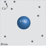
VI The Microscale: a Single CO2 Bubble
In this section, we discuss a mechanism that leads to a carbonate-encrusted bubble, in which a single bubble of pure CO2 surrounded by brine develops a crust at the interface. Unlike the upscaled case discussed above, where each region consists of the same ingredients but with a different concentration, here we have a pure bubble (no upscaling) with only CO2, either in a liquid phase or gas phase. The problem is pictured in Fig. 6.
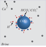
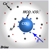

In this case, no chemical reactions occur inside the CO2 bubble; reactions instead occur only at the interface with the brine. The CO2 then dissolves into the brine, creates charged carbonate species and reduces the pH in its vicinity. Most of the components diffuse slowly away from the interface, however, the protons in water diffuse faster due to structural diffusion, also known as the Grotthoss mechanism 95A . The concentration gradient with unequal diffusivities generates an electrical field that slows down the rapidly diffusing protons, but also attracts positively charged minerals toward the interface. (The dynamics is described by the Nernst-Planck equations 97RAM ; 12AVMBBB ). This leads to supersaturation at the interface and mineral precipitation. This process suggest that an isolated bubble can remain stable due to a self-sealing mechanism.
VII Discussion and Conclusion
We have shown that in a system of reactive fluids, a gradient in the concentration between regions leads to a supersaturation at the interface and to precipitation and porosity loss. A local change in the porosity reduces permeability and may cause mechanical separation. This process is important in understanding the long-term sequestration of carbon dioxide in subsurface geological formation. We predict that a small domain of a region consisting mostly of the carbonate species in an acidic environment will dissolve completely into the brine. Larger domains are more likely to be self-sealed, and only a fraction of the carbonate species will be precipitated. For a single CO2 bubble in brine solution, we suggest a mechanism that causes self-sealing due to the pH gradient at the interface of the bubble and structural diffusion.
Our results suggest that only a small fraction of the injected CO2 is converted to a solid mineral. The remainder stays in its dissolved ionic form or is trapped in its original form. Whether a domain will go into dissolution trapping or mechanical separation depends on the concentration gradients, the properties of the rock and the porosity available for transport.
Acknowledgements
We thank M. Z. Bazant, A. Kudrolli and S. R. Pride for sharing their thoughts and helpful discussions. The work was supported by the Center for Nanoscale Control of Geologic CO2, an Energy Frontier Research Center funded by the US Department of Energy, Office of Science, Office of Basic Energy Sciences under Award No. DE-AC02-05CH11231, subcontract 6896518.
References
- (1) Metz B, Davidson O, De Coninck H, Loos M, Meyer L. 2007 IPCC special report on carbon dioxide capture and storage: Prepared by working group III of the intergovernmental panel on climate change. IPCC 4, Cambridge University Press: Cambridge, United Kingdom and New York, USA..
- (2) Schrag DP. 2007 Preparing to capture carbon. Science. 315 (5813):812–813.
- (3) Bachu S, Gunter W, Perkins E. 1994 Aquifer disposal of CO2: Hydrodynamic and mineral trapping. Energy Conversion and Management. 35(4):269–279.
- (4) Lackner KS. 2003 A guide to CO2 sequestration. Science. 300(5626):1677–1678.
- (5) Song J, Zhang D. 2013 Comprehensive Review of Caprock-Sealing Mechanisms for Geologic Carbon Sequestration. Environmental Science & Technology. 47(1):9–22.
- (6) Bachu S, Adams J. 2003 Sequestration of CO2 in geological media in response to climate change: capacity of deep saline aquifers to sequester CO2 in solution. Energy Conversion and Management. 44(20):3151–3175.
- (7) Chiquet P, Broseta D, Thibeau S. 2007 Wettability alteration of caprock minerals by carbon dioxide. Geofluids. 7(2):112–122.
- (8) Baines SJ, Worden RH. 2004 The long-term fate of CO2 in the subsurface: natural analogues for CO2 storage. Geological Society, London, Special Publications. 233(1):59–85.
- (9) Gunter WD, Bachu S, Benson S. 2004 The role of hydrogeological and geochemical trapping in sedimentary basins for secure geological storage of carbon dioxide. Geological Society, London, Special Publications. 233(1):129–145.
- (10) Dias MM, Wilkinson D. 1986 Percolation with trapping. Journal of Physics A: Mathematical and General. 19(15):3131.
- (11) Stauffer D, Aharony A. 1992 Introduction to percolation theory. Taylor and Francis, London.
- (12) Wilkinson D, Willemsen JF. 1983 Invasion percolation: a new form of percolation theory. Journal of Physics A: Mathematical and General. 16(14):3365.
- (13) Feder J. 1988 Fractals. Plenum Press, New York.
- (14) Reeves D, Rothman DH. 2012 Impact of structured heterogeneities on reactive two-phase porous flow. Physical Review E. 86(3):031120.
- (15) Noiriel C, Steefel CI, Yang L, Ajo-Franklin J. 2012 Upscaling calcium carbonate precipitation rates from pore to continuum scale. Chemical Geology. 318:60–74.
- (16) Chafetz H, Rush PF, Utech NM. 1991 Microenvironmental controls on mineralogy and habit of CaCO3 precipitates: an example from an active travertine system. Sedimentology. 38(1):107–126.
- (17) Fouke BW, Farmer JD, Des Marais DJ, Pratt L, Sturchio NC, Burns PC, et al. 2000 Depositional Facies and Aqueous-Solid Geochemistry of Travertine-Depositing Hot Springs (Angel Terrace, Mammoth Hot Springs, Yellowstone National Park, U.S.A.). Journal of Sedimentary Research. 70(3):565–585.
- (18) Tsai PA, Riesing K, Stone HA. 2013 Density-driven convection enhanced by an inclined boundary: Implications for geological CO2 storage. Physical Review E. 87(1):011003.
- (19) Liu Q, Maroto-Valer MM. 2010 Investigation of the pH effect of a typical host rock and buffer solution on CO2 sequestration in synthetic brines. Fuel Processing Technology. 91(10):1321–1329.
- (20) Kharaka Y, Cole D, Hovorka S, Gunter W, Knauss K, Freifeld B.2006 Gas-water-rock interactions in Frio Formation following CO2 injection: Implications for the storage of greenhouse gases in sedimentary basins. Geology. 34(7):577–580.
- (21) Silin D, Tomutsa L, Benson SM, Patzek TW. 2011 Microtomography and pore-scale modeling of two-phase fluid distribution. Transport in Porous Media. 86(2):495–515.
- (22) Matter JM, Kelemen PB. 2009 Permanent storage of carbon dioxide in geological reservoirs by mineral carbonation. Nature Geoscience. 2(12):837–841.
- (23) Zeebe RE, Wolf-Gladrow D. 2001 CO2 in Seawater: Equilibrium, Kinetics, Isotopes: Equilibrium, Kinetics, Isotopes. Elsevier.
- (24) Druckenmiller ML, Maroto-Valer MM. 2005 Carbon sequestration using brine of adjusted pH to form mineral carbonates. Fuel Processing Technology. 86(14):1599–1614.
- (25) Plummer L, Wigley T, Parkhurst D. 1978 The kinetics of calcite dissolution in CO2-water systems at 5 degrees to 60 degrees C and 0.0 to 1.0 atm CO2. American Journal of Science. 278(2):179–216.
- (26) Chou L, Garrels RM, Wollast R. 1989 Comparative study of the kinetics and mechanisms of dissolution of carbonate minerals. Chemical Geology. 78(3):269–282.
- (27) DePaolo DJ. 2011 Surface kinetic model for isotopic and trace element fractionation during precipitation of calcite from aqueous solutions. Geochimica et Cosmochimica Acta. 75(4):1039–1056.
- (28) Li L, Steefel CI, Yang L. 2008 Scale dependence of mineral dissolution rates within single pores and fractures. Geochimica et Cosmochimica Acta. 72(2):360–377.
- (29) Blyth M, Pozrikidis C. 2003 Heat conduction across irregular and fractal-like surfaces. International journal of heat and mass transfer. 46(8):1329–1339.
- (30) Sahimi M. 2012 Flow and transport in porous media and fractured rock: from classical methods to modern approaches. John Wiley & Sons, Germany.
- (31) Sahimi M, Jue VL. 1989 Diffusion of large molecules in porous media. Physical review letters. 62(6):629.
- (32) Agmon N. 1995 The grotthuss mechanism. Chemical Physics Letters. 244(5):456–462.
- (33) Ramírez P, Alcaraz A, Mafé S. 1997 Effects of pH on ion transport in weak amphoteric membranes. Journal of Electroanalytical Chemistry. 436(1):119–125.
- (34) Andersen MB, Van Soestbergen M, Mani A, Bruus H, Biesheuvel P, Bazant M. 2012 Current-induced membrane discharge. Physical review letters. 109(10):108301.