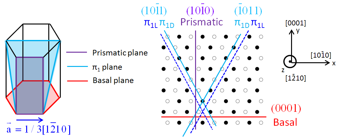
First order pyramidal slip
of screw dislocations in zirconium***Article
published in Metall. Mater. Trans. A,
symposium Multiscale perspectives on plasticity in hcp metals,
TMS 2014 annual meeting;
http://dx.doi.org/10.1007/s11661-014-2568-7
Nermine Chaari1, Emmanuel Clouet1, and David Rodney2
1CEA, DEN, Service de Recherches de Métallurgie physique;
Gif-sur-Yvette 91191, France
2Institut Lumière Matière, Université Lyon 1, CNRS, UMR 5306;
Villeurbanne, 69622, France
Keywords: Zirconium, Cross-slip, screw dislocations, etc.
Abstract
Atomistic simulations, based either on an empirical interatomic potential or on ab initio calculations, are used to study the pyramidal glide of a screw dislocation in hexagonal close-packed zirconium. Generalized stacking fault calculations reveal a metastable stacking fault in the first order pyramidal plane, which corresponds to an elementary pyramidal twin. This fault is at the origin of a metastable configuration of the screw dislocation in zirconium, which spontaneously appears when the dislocation glides in the pyramidal plane.
Introduction
Hexagonal close-packed (hcp) Zirconium is an important material for the nuclear industry where it is used as structural component in nuclear reactors. In particular the cladding of nuclear fuel is made of zirconium alloys. Like most crystalline material, the mechanical behavior is mainly driven by dislocations motion.
In -zirconium, dislocations with Burgers vector , named dislocations, are the most frequently observed with transmission electron microscopy [1, 2, 3]. These dislocations glide principally in prismatic planes [4, 2, 5] due to a lower critical resolved shear stress than in the basal and pyramidal planes [1, 6, 7, 8, 9, 3]. At low temperature, screw components of dislocations can be distinguished as long rectilinear segments while mixed and edge components are observed in their equilibrium state as curved lines. This is because screw dislocations have a larger lattice friction opposing their motion and making them less mobile compared to mixed and edge dislocations [1, 2, 3]. For this reason, screw dislocations with Burgers vector control the material plasticity at low temperature and are mostly considered in the literature. In addition, experiments show that the ease of glide of screw dislocations in the prismatic planes is strongly temperature dependent and also decreases when the amount of impurities such as oxygen, sulfur and carbon, increases in the material [5, 10, 11, 12, 3].
At higher temperatures and strain levels, secondary slip systems are activated such as first order pyramidal slip [13], which has been evidenced at room temperature as an important glide system to accommodate the crystal deformation along the direction. Thermal activation also enhances dislocation cross-slip. Experimental evidence shows that above 300 K (573∘C), screw dislocations with Burgers vector initially gliding in the prismatic planes, may leave their habit plane to glide in a first order pyramidal plane ()[10, 3, 14], or less frequently in a basal plane [6, 15, 16, 17]. Screw dislocations cross slip is more frequently observed with increasing impurity content, especially with oxygen, while the hardening effect due to impurities manifests itself on the prismatic glide [3, 11, 10, 5], as mentioned above. The same dislocation behavior has also been evidenced in titanium [18, 19, 20, 21, 22, 23], a transition metal with similar properties to zirconium.
In agreement with the experiments, atomistic simulations have established that, in pure zirconium, a screw dislocation with Burgers vector dissociates spontaneously in the prismatic plane into two partial dislocations with Burgers vector [24, 25]. The dissociation is explained by a stable stacking fault with low energy in the prismatic plane [26, 27, 24]. In turn, dissociation leads to a low lattice friction that makes screw dislocations glide easily in the prismatic planes [28, 24]. Considering pyramidal and basal slip of dislocations in pure zirconium, it has been shown in a previous article that both slip systems share the same thermally-activated mechanism involving a metastable core structure, where the screw dislocation with Burgers vector partially spreads in a pyramidal plane [29]. The aim of the present paper is to study in more details pyramidal slip and to justify the glide mechanism suggested in Ref. [29].
As dislocation mobility results from their core structure, accurate atomic-scale study of the dislocation core is required to understand their mobility. Besides, it has been shown that in hcp transition metals, the relative ease of dislocation glide is directly related to the stacking fault energies in the glide planes, which are in turn controlled by the electronic structure of the metal [30]. Atomistic simulations incorporating a full description of the electronic structure are therefore necessary to model dislocations in zirconium. In the present work, we used both ab initio calculations and an empirical potential to calculate the energy associated with shearing the hcp lattice in a pyramidal plane, both homogeneously to determine generalized stacking faults, and inhomogeneously when a dislocation, initially dissociated in a prismatic plane glides along a pyramidal plane.
Methods
As described in previous papers [24, 29], we performed ab initio calculations based on the density functional theory using the PWSCF code [31]. Atomistic simulations with the embedded atom method (EAM) potential developed by Mendelev and Ackland (potential #3)[32] were also performed to study the effect of simulation cell size. A comparison between results obtained with both energy models was established to assess the ability of this empirical potential to describe pyramidal slip.
Dislocation core structure and glide are directly related to the stacking fault energy in the glide plane. To characterize the shearing of the crystal in the pyramidal plane, we calculated the generalized stacking fault [4] in this plane using fully periodic boundary conditions. Only one fault is introduced in the simulation cell, and the corresponding shift is applied to the periodicity vector perpendicular to the fault plane. Atom relaxation is only allowed in the direction perpendicular to the fault plane, but we also performed calculations with full atomic relaxation to identify stable stacking faults.
To model dislocations, we used a fully periodic arrangement of dislocation dipole described as an S arrangement in Ref. [24]. The dimensions of the simulation cells are in the direction, in the direction and in the direction along the dislocation line ( and are two integers). Atoms are relaxed until all components of the atomic forces are smaller than 10 meV/Å. We checked for some configurations that relaxation at 2 meV/Å does not change any of our results. We employed the Nudged elastic Band (NEB) method [33] to determine the energy barrier against dislocation glide in the first order pyramidal plane. This method gives the minimum energy path between two stable states. All energy barriers are calculated while moving both dislocations composing the dipole in the same direction and the path is relaxed with a tolerance on atomic forces of 20 meV/Å.
Stacking fault energy in the pyramidal plane
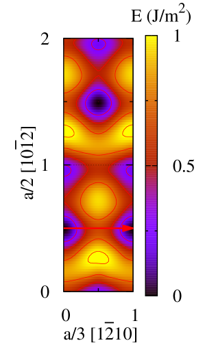
Since dislocation glide is directly related to the stacking fault energy in the corresponding plane, we started by investigating stacking fault energies in the first order pyramidal plane. In the hcp structure, pyramidal planes are corrugated. As a consequence, there are two different ways to shear the crystal along a pyramidal plane. The crystal might be sheared either inside a corrugated pyramidal plane, which we call a dense plane , or between two pyramidal corrugated planes, i.e. inside a loose plane (Fig. 1). The generalized stacking fault is calculated for both types of pyramidal planes using both ab initio calculations and the EAM potential.
We used a simulation cell with a height , where Å is the height of the elementary cell and is the number of the atomic planes separating two faults. The convergence of our results with respect to the simulation cell height has been checked with the EAM potential.
The results obtained with ab initio calculations and with the EAM potential in both pyramidal and planes are in good agreement. We show in Fig. 2 the -surfaces obtained with ab initio calculations in both pyramidal planes. From a general point of view, the -surfaces show that shearing the crystal in a plane costs higher energy than in the plane. This is a consequence of the fact that atoms are close to each other in this plane, and the shearing may bring them closer, which strongly increases the energy. But this high energy landscape is explored only when a fault component is involved. Focusing now on the direction, which is the relevant direction for dislocation glide, the -surfaces calculated in both and plane show a valley of low energy along this direction.
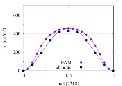
To compare both pyramidal planes, we plot in Fig. 3 the generalized stacking fault energy only along the direction for both planes. The energy obtained with ab initio calculations is higher than with the EAM potential in the case of the plane, while it is nearly the same for the plane. According to the EAM potential, the energy cost to shear the crystal along the direction in a pyramidal plane is almost the same for both and planes. Ab initio calculations, however, predict that it is easier to shear in a plane than in a plane. Our work therefore shows that both and pyramidal planes may need to be considered when studying stacking faults in the first order pyramidal plane. This contrasts with the previous stacking fault calculations in hcp materials where only the plane was considered [27, 34, 35].
Considering both Figs. 2 and 3, no energy minimum is found along the direction, or in its immediate vicinity. This is true for the ab initio calculations and the EAM potential. One should notice that the present -surfaces were obtained by relaxing the atoms only perpendicularly to the fault plane. A full atomic relaxation, however, allows for some atomic shuffling and reveals an energy minimum that corresponds to a metastable stacking fault in the plane. The corresponding fault vector sketched by red arrow in Fig. 2(b), is , where and is a component orthogonal to to be detailed below. This minimum is obtained with both ab initio calculations and the EAM potential. On the other hand, no relevant minimum could be found for the plane, even with full atomic relaxations.
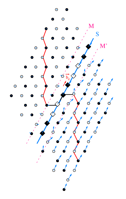
The atomic structure of the metastable stacking fault is shown in Fig. 4. The displacement map shows that in the shearing direction , the atoms below the shearing plane S have their color switched, which means that they have been displaced by . The shearing is thus perfectly localized in the S plane. Perpendicularly to the shearing direction, the blue arrows show a displacement of all the atoms below the S plane following one same vector , which corresponds to the orthogonal component of the fault vector, as well as a shuffling of the atoms which is extended to several planes at both sides of the S plane. This shuffling explains why the metastable fault did not appear on the -surfaces of Fig. 2, where only atomic relaxation perpendicularly to the fault plane was allowed.
Analysis of this metastable core structure reveals that it corresponds to an elementary two-layer pyramidal twin [29] bordered by the M and M’ mirror planes, as illustrated by the broken line on Fig. 4. We also looked at the positions of the first nearest neighbors for each atom and compared the obtained pattern with the ones existing in a perfect hcp structure, both for the parent and the twinned lattices. We thus managed to characterize whether an atom belongs to the parent or the twinned hcp lattice. On figure 4, atoms plotted with diamonds corresponds to the atoms belonging to the twin layer.
The twin is produced by the glide of a two-layer disconnection with a Burgers vector that corresponds to the fault vector where the edge component of the disconnection is defined by ( is the ratio) [36, 37]. Two layer disconnections are well-known to be stable on pyramidal twins [37, 38, 39, 40, 41, 36, 42], but the stability of the corresponding two-layer twin was so far unknown.
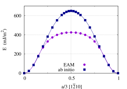
The stacking fault energy deduced from ab initio calculations is mJ m-2. It is lower than the energy of the prismatic stacking fault ( mJ m-2) [24]. Compared to the ab initio value, the EAM potential overestimates the pyramidal stacking fault energy ( mJ m-2). This leads to a higher energy than for the prismatic fault ( mJ m-2)
Peierls barrier in the pyramidal plane
Considering the results for the generalized stacking faults, we conclude that it is important to include both pyramidal and planes in our study. We thus investigate in this part the glide of an screw dislocation in first order pyramidal planes, for both and planes.
EAM
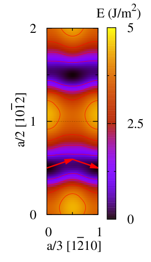
Starting from a dislocation in its equilibrium configuration, i.e. initially spread in a prismatic plane (Fig. 7(a)), we calculated the energy encountered by the dislocation to overcome a Peierls valley in the pyramidal plane, moving to a final equilibrium state where the dislocation spreads in the next prismatic plane. We used the NEB method to calculate the Peierls barrier in both pyramidal and planes with the EAM potential. The initial path of the dislocation is obtained by a linear interpolation between the initial and the final states with the cut created by the dislocation glide localized in the chosen first order pyramidal plane.
The results are shown in Fig. 5. The energy barrier in the plane is twice higher than in the plane. Thus, according to the EAM potential, it is easier for the dislocation to glide in the plane than in the plane.
The energy path obtained in the plane shows a local minimum at halfway across the migration. This minimum corresponds to an intermediate metastable configuration of the screw dislocation (Fig. 7(b)), to be described in more details below.
Ab initio
We only consider dislocation glide in the plane for the ab initio calculations. This is motivated by the ab initio results for the generalized stacking faults, showing that the plane is easier to shear in the direction than the plane (Fig. 3), as well as by the Peierls barrier obtained with the EAM potential, showing that dislocation glide in the plane costs less energy than in the plane (Fig. 5).
Ab initio calculations of the Peierls barrier in the plane were performed for different simulation cell sizes. The minimum energy paths obtained are illustrated in Fig. 6. They all show a local minimum halfway across the migration, in agreement with the EAM results. This minimum corresponds to the same intermediate metastable configuration of the screw dislocation as found with the EAM potential.
The ab initio energy barrier is twice lower than with the EAM potential. The difference in energy between ab initio and EAM is related to the fact that the Mendelev potential overestimates the energy of the pyramidal metastable stacking fault. As a consequence this empirical potential leads to a higher Peierls barrier in the pyramidal plane.
Metastable configuration of the screw dislocation in zirconium
Both ab initio calculations and the EAM potential showed that pyramidal glide involves an intermediate metastable configuration of the screw dislocation appearing halfway across the migration. In the following, a detailed description of this metastable configuration is proposed.
Core structure
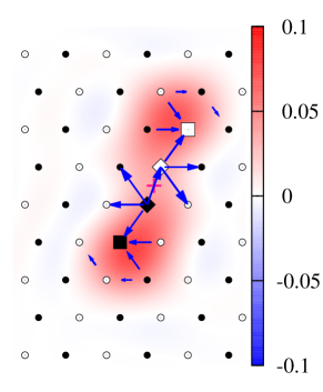
Fig. 7 shows the core structure of the two possible configurations obtained for the screw dislocation with ab initio calculations and with the EAM potential. The differential displacement maps have been superimposed to the Nye tensor distribution calculated following the method of Hartley and Mishin [43]. Only the screw component of the Nye tensors is plotted in each structure. This Burgers vector density is deduced from the position variation of the nearest neighbors for each corresponding atom. In a perfect hcp structure each atom has twelve nearest neighbors forming a defined pattern. However in a faulted structure, this number of nearest neighbors can be different with different corresponding patterns. In the figure, atoms belonging to a pattern that corresponds to a prismatic stacking fault have been plotted as squares while those belonging to a pattern that corresponds to the pyramidal twin described before are plotted as diamonds. We can see through Fig. 7 that ab initio calculations and EAM potential results are in good agreement with the same metastable core obtained in both cases.
The equilibrium configuration of the dislocation (Fig. 7(a) and (c)) shows a spread in the prismatic plane in agreement with the literature [24, 25]. The dissociation of the dislocation into two partials is illustrated by two local extrema in the Nye tensor distribution and the prismatic stacking fault in the core is highlighted by the squares showing the atoms involved in the fault.
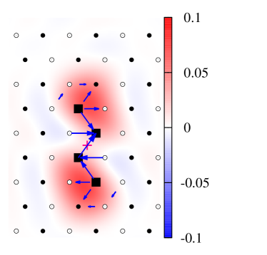
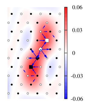
Analyzing the displacement maps of the metastable core structure (Fig. 7(b) and (d)), we show that the dislocation is spread in three different crystallographic planes at the same time: in the core center, the dislocation lies in a pyramidal plane while it lies in two adjacent prismatic planes at the extremities. The two central atoms sketched by black and white diamonds (Fig. 7(b) and (d)) witness of the presence of the pyramidal twin pattern, while the squares result from a local shearing in the prismatic plane.
The pyramidal spreading in the core center is explained by the metastable stacking fault evidenced above in the pyramidal plane with a fault vector . The central part of the core thus corresponds to an elementary two layer twin of a finite extension. Since the screw component of the fault vector, , is identical in both the prismatic and pyramidal faults, there is no discontinuity in the screw direction at the intersection between the faults. The pyramidal fault is thus bordered at its intersections with the prismatic fault by two edge disconnections of slip vectors , while the prismatic faults end with screw partial dislocations with Burgers vectors. This can be seen through the Nye tensor distribution plot in Fig. 7(b) and (d) where two partial dislocations are distinguished in two neighboring prismatic planes.
The metastable core may thus be described as two partial dislocations spread in two adjacent prismatic planes, separated by two prismatic stacking faults and a pyramidal nanotwin in-between [29]. The prismatic stacking faults are linked to the nanotwin by stair-rods forming a dipole of disconnections (). The corresponding decomposition of the total Burgers vector is
where is the ratio.
Core energy
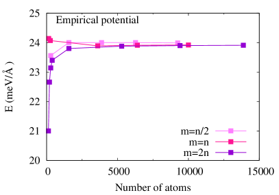
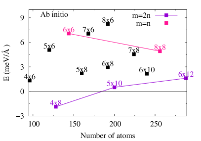
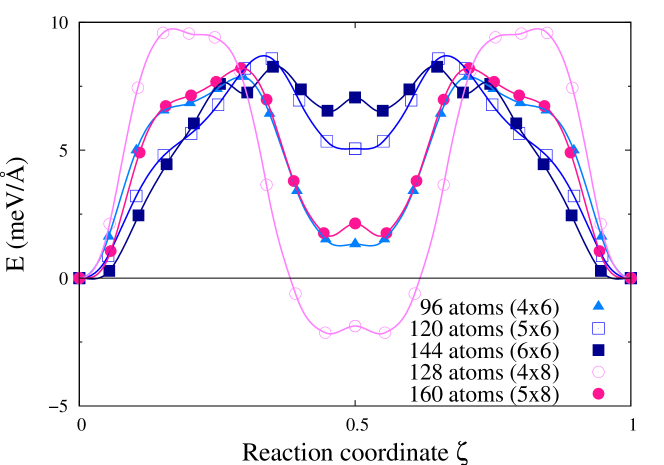
Fig. 8 summarizes, for different cell sizes, the excess energy of the metastable configuration, with respect to the energy of the equilibrium configuration fully dissociated in the prismatic plane. With the EAM potential, this excess energy is always positive, confirming that the metastable core is less favorable than the prismatic configuration. Convergence of the results is obtained for simulation cells containing more than 2000 atoms (Fig. 8(a)), with an excess energy of meV/Å. Different simulation cell shapes lead to different convergence behaviors. At small sizes, an upper bound of the converged excess energy is obtained with shapes defined by , whereas a lower bound is obtained with .
Ab initio calculations lead to a lower excess energy (Fig. 8(b)). As a consequence, stability inversion was observed for very small simulation cells ( cell containing only 128 atoms). However, larger simulation cells confirm that the configuration partially spread in the pyramidal plane is metastable. Since ab initio calculations are more expensive and limited to few hundred atoms, it was not possible to reach a converged value of the energy. However, the same dependence of the convergence rate with the cell shape was observed with the ab initio calculations and with the EAM potential. An upper limit of the energy is thus given by the cells and a lower limit by the cells. Our ab initio calculations therefore lead to an excess energy meV/Å.
Conclusion
In the present work, based on generalized stacking fault calculations in the first order pyramidal plane, we demonstrated that shearing along the direction inside a dense pyramidal plane costs less energy than between two corrugated planes. In addition, calculations showed a metastable stacking fault in the pyramidal plane, which corresponds to an elementary pyramidal two-layer twin. This metastable stacking fault is at the origin of the new metastable core configuration of the screw dislocation in zirconium, which appears halfway across the migration path when the dislocation glides in a pyramidal plane. This metastable configuration presents an unusual core structure with an incipient two-layer twin in its center.
We conclude that there are two possible configurations of the screw dislocation in zirconium. The one with the lower core energy, is dissociated in the prismatic plane and responsible for the easy glide in this plane [24]. The second configuration is metastable and appears during pyramidal and basal slips [29]. The results show a good agreement between ab initio calculations and the Mendelev empirical potential since, qualitatively, both lead to the same glide mechanism and metastable core. This work is a first step toward understanding cross-slip in zirconium, showing a new and unexpected relation between dislocation glide and twinning, two essential motors for hcp plasticity.
Acknowledgments
This work was performed using HPC resources from GENCI-CINES, -CCRT and -IDRIS (Grants 2013-096847). The authors also acknowledge PRACE for awarding access to the Marenostrum resources based in Barcelona Supercomputing Center (project DIMAIM).
References
- [1] E.J Rapperport. Room temperature deformation processes in zirconium. Acta Metall., 7:254–260, 1959.
- [2] D. Caillard and J. L. Martin. Thermally Activated Mechanisms in Crystal Plasticity. Pergamon, Amsterdam, 2003.
- [3] Franck Ferrer. Étude des Mécanismes de Déformation du Zirconium entre 25C et 400C. Influence d’une Faible Teneur en Soufre. PhD thesis, École Polytechnique, France, 2000.
- [4] V. Vitek and V. Paidar. Non-planar dislocation cores: A ubiquitous phenomenon affecting mechanical properties of crystalline materials. In John Hirth, editor, Dislocations in Solids, volume 14, chapter 87, pages 439–514. Elsevier, 2008.
- [5] L. P. Kubin. Dislocations, mesoscale simulations and plastic flow. Oxford University Press, Oxford, UK, first edition edition, 2013.
- [6] A Akhtar and A Teghtsoonian. Plastic deformation of zirconium single crystals. Acta Metall., 19:655–663, 1971.
- [7] A. Akhtar. Prismatic slip in zirconium single crystals at elevated temperatures. Metall. Mater. Trans. A, 6:1217–1222, 1975.
- [8] W. Tyson. Basal and prismatic slip in h.c.p. crystals. Acta Metall., 15:574–577, 1967.
- [9] A. Akhtar. Schmid’s law and prismatic slip of zirconium. Scripta Metall., 9:859–861, 1975.
- [10] D. H. Baldwin and R. E. Reedhill. Some effects of oxygen on tensile deformation of polycrystalline zirconium. Trans. AIME, 242:661, 1968.
- [11] D. H. Sastry, Y. V. R. K. Prasad, and K. I. Vasu. An evaluation of rate-controlling obstacles for low-temperature deformation of zirconium. J. Mater. Sci., 6:332–341, 1971.
- [12] D. Mills and G. B. Craig. The plastic deformation of zirconium-oxygen alloy single crystals in the range 77 to 950 k. Trans. AIME, 242:1881–1890, 1968.
- [13] H. Numakura, Y. Minonishi, and M. Koiwa. slip in zirconium. Philos. Mag. A, 63:1077–1084, 1991.
- [14] Martin Rautenberg, Xavier Feaugas, Dominique Poquillon, and Jean-Marc Cloué. Microstructural characterization of creep anisotropy at 673K in the M5(R) alloy. Acta Mater., 60:4319–4327, 2012.
- [15] A. Akhtar. Basal slip in zirconium. Acta Metall., 21:1–11, 1973.
- [16] G.G. Yapici, C.N. Tomé, I.J. Beyerlein, I. Karaman, S.C. Vogel, and C. Liu. Plastic flow anisotropy of pure zirconium after severe plastic deformation at room temperature. Acta Mater., 57:4855–4865, 2009.
- [17] Marko Knezevic, Irene J. Beyerlein, Thomas Nizolek, Nathan A. Mara, and Tresa M. Pollock. Anomalous basal slip activity in zirconium under high-strain deformation. Mater. Res. Lett., 1:133–140, 2013.
- [18] A. T. Churchman. The slip modes of titanium and the effect of purity on their occurrence during tensile deformation of single crystals. Proc. R. Soc. A, 226:216–226, 1954.
- [19] D. Shechtman and D. G. Brandon. Orientation dependent slip in polycrystalline titanium. J. Mater. Sci., 8:1233–1237, 1973.
- [20] F. D. Rosi, C. A. Dube, and B. H. Alexander. Mechanism of plastic flow in titanium - determination of slip and twinning elements. Trans. AIME, 197:257–265, 1953.
- [21] S. Farenc, D. Caillard, and A. Couret. An in situ study of prismatic glide in titanium at low temperatures. Acta Metall. Mater., 41:2701 – 2709, 1993.
- [22] Shigehisa Naka. Étude des mécanismes de déformation plastique à basse température de monocristaux de titane . PhD thesis, Univ. Paris-Sud, 1983.
- [23] S. Naka, A. Lasalmonie, P. Costa, and L. P. Kubin. The low-temperature plastic deformation of titanium and the core structure of -type screw dislocations. Philos. Mag. A, 57:717–740, 1988.
- [24] E. Clouet. Screw dislocation in zirconium: An ab initio study. Phys. Rev. B, 86:144104, 2012.
- [25] D. Bacon and V. Vitek. Atomic-scale modeling of dislocations and related properties in the hexagonal-close-packed metals. Metall. Mater. Trans. A, 33:721–733, 2002.
- [26] C. Domain, R. Besson, and A. Legris. Atomic-scale ab initio study of the Zr-H system: II. interaction of H with plane defects and mechanical properties. Acta Mater., 52:1495–1502, 2004.
- [27] A. Poty, J.-M. Raulot, H. Xu, J. Bai, C. Schuman, J.-S. Lecomte, M.-J. Philippe, and C. Esling. Classification of the critical resolved shear stress in the hexagonal-close-packed materials by atomic simulation: Application to -zirconium and -titanium. J. Appl. Phys., 110:014905, 2011.
- [28] H. A. Khater and D. J. Bacon. Dislocation core structure and dynamics in two atomic models of alpha-zirconium. Acta Mater., 58:2978–2987, 2010.
- [29] Nermine Chaari, Emmanuel Clouet, and David Rodney. First principles study of secondary slip in zirconium. Phys. Rev. Lett., 112(7):075504, 2014.
- [30] B. Legrand. Relations entre la structure électronique et la facilité de glissement dans les métaux hexagonaux compacts. Philos. Mag. B, 49:171–184, 1984.
- [31] Paolo Giannozzi et al. QUANTUM ESPRESSO: a modular and open-source software project for quantum simulations of materials. J. Phys.: Condens. Matter, 21(39):395502, 2009.
- [32] M. I. Mendelev and G. J. Ackland. Development of an interatomic potential for the simulation of phase transformations in zirconium. Philos. Mag. Lett., 87:349–359, 2007.
- [33] Graeme Henkelman and Hannes Jónsson. Improved tangent estimate in the nudged elastic band method for finding minimum energy paths and saddle points. J. Chem. Phys., 113:9978–9985, 2000.
- [34] M. Ghazisaeidi and D.R. Trinkle. Core structure of a screw dislocation in Ti from density functional theory and classical potentials. Acta Mater., 60:1287–1292, 2012.
- [35] Ilgyou Shin and Emily A Carter. Orbital-free density functional theory simulations of dislocations in magnesium. Modelling Simul. Mater. Sci. Eng., 20:015006, 2012.
- [36] A. Serra, R. C. Pond, and D. J. Bacon. Computer simulation of the structure and mobility of twinning disclocations in h.c.p. metals. Acta Metall. Mater., 39:1469–1480, 1991.
- [37] J. Wang, I.J. Beyerlein, J.P. Hirth, and C.N. Tomé. Twinning dislocations on and planes in hexagonal close-packed crystals. Acta Mater., 59:3990–4001, 2011.
- [38] L. Leclercq, L. Capolungo, and D. Rodney. Atomic-scale comparison between and twin growth mechanisms in magnesium. Mat. Res. Lett., 2:1–8, 2014.
- [39] L. A. Bursill, Ju Lin Peng, Xu-Dong Fan, Y. Kasukabe, and Y. Yamada. twin dislocation structures in evaporated titanium thin films. Phil. Mag. Lett., 71(5):269–273, 1995.
- [40] B. Li and E. Ma. Zonal dislocations mediating twinning in magnesium. Acta Mater., 57(6):1734–1743, 2009.
- [41] R. C. Pond, D. J. Bacon, and A. Serra. Interfacial structure of twins and twinning dislocations in titanium. Phil. Mag. Lett., 71(5):275–284, 1995.
- [42] J Wang, I J Beyerlein, and J P Hirth. Nucleation of elementary and twinning dislocations at a twin boundary in hexagonal close-packed crystals. Modelling Simul. Mater. Sci. Eng., 20(2):024001, Mar 2012.
- [43] C. S. Hartley and Y. Mishin. Characterization and visualization of the lattice misfit associated with dislocation cores. Acta Mater., 53:1313–1321, 2005.