SELECTED PROPERTIES OF OPTICAL SPATIAL SOLITONS IN PHOTOREFRACTIVE MEDIA AND THEIR IMPORTANT APPLICATIONS
Abstract
Some selected important properties of photorefractive spatial solitons and their applications have been reviewed in the present paper. Using band transport model, the governing principle of photorefractive nonlinearity has been addressed and nonlinear dynamical equations of spatial solitons owing to this nonlinearity have been discussed. Mechanisms of formation of screening and photovoltaic solitons of three different configurations i.e., bright, dark and grey varieties have been examined. Incoherently coupled vector solitons due to single and two-photon photorefractive phenomena have been highlighted. Modulation instability, which is precursor to soliton formation has been also discused briefly. Finally possible applications of photorefractive spatial solitons have been highlighted.
Fax No: +91-6512276052, Tel No: +91-6512275522, Mobile No: +91-9431326757,
Email of corresponding author: swakonar@yahoo.com, skonar@bitmesra.ac.in
1 Introduction
Nonlinear optics has lead the way of several fundamental discoveries, elegant and fascinating one of these is the optical solitons. These solitons are extensively studied since last three decades not only because of their mathematical elegance but also due to applications in photonics and optical communications [1, 2, 3, 4, 5, 6, 7, 8, 9, 10, 11, 12, 13, 14, 15, 16, 17, 18, 19, 20, 21, 22, 23, 24]. Optical beams and pulses spread during propagation due to self-diffraction or dispersion. This broadening can be arrested in optical nonlinear media resulting in stable optical beams or pulses whose spreading is exactly balanced by optical nonlinearity and these self trapped beams or pulses are known as optical solitons [2, 3, 5, 7]. Optical spatial solitons are self-trapped optical beams whose spreading due to diffraction is exactly balanced by optical nonlinearity induced self lensing mechanisms.The optical beam induces a refractive index change in the medium thereby creating an optical waveguide which subsequently guides the beam. Thus, the beam first creates an waveguide and then self-trapped and guided in the waveguide created by itself. An optical temporal soliton on the otherhand is a nonspreading optical pulse whose broadening due to group velocity dispersion is exactly balanced by the nonlinearity induced self phase modulation. More explicitly, the group velocity dispersion produces a chirp in the propagating pulse which is balanced by the opposite chirp created by nonlinearity. Exact balance of these opposite chirps results in the formation of optical temporal solitons.
1.1 Optical Solitons or Optical Solitary Waves?
Way back in 1995, Zabusky and Kruskal [13] introduced the term solitons to reflect the particle like properties of stable self-trapped waves in nonlinear media. The motivation behind this was the fact that the shape of these self-trapped wavepackets remain intact even after collision. Historically, this term was reserved for those wavepackets which obey integrable partial differential equations that can be solved by inverse scattering theory [10, 11, 13]. Solitons, which are solutions of these equations, remain invariant even after collision since they undergo elastic collision. Optical beam and pulse propagation in Kerr nonlinear media are governed by partial differential equations which are integrable via inverse scattering technique, hence, optical solitons can be created in such media. However, most physical optical systems, for example photorefractive media, possess non-Kerr types of nonlinearity in which optical beams or pulses are described by dynamical equations that are though partial differential equations but not integrable by inverse scattering technique. Self-trapped solutions of these non-integrable equations are known as ’solitary waves’. These solitary waves are not solitons since collision between these solitary waves is not always elastic [8, 9, 14]. For example, under specific conditions, two photorefractive optical spatial solitary waves may coalesce to form a single solitary wave and a single solitary wave might undergo fission to give birth to new solitons. However, these solitary waves in many cases play extremely important role in several applications. In literature, despite their shortcoming, it is now quite common to loosely refer all self-trapped optical solitary waves as solitons regardless of whether they obey integrable partial differential equation or not.
1.2 Emergence of Photorefractive Optical Spatial Solitons
Guiding of optical beams in the self created waveguide was first pointed out by Askaryan in 1962 [12]. Kelly [15] pointed out that in Kerr nonlinear media spatial solitons with two transverse dimensions(2D) are unstable and undergo catastrophic collapse. Soon it was realised that spatial solitons with only one transverse dimensions(1D) are stable in Kerr nonlinear media [15]. Subsequently, it was also realized that catastrophic collapse of 2D solitons could be avoided in an optical media possessing saturating nonlinearity [16]. Therefore, the idea of saturating nonlinearity was the key to the discovery of a plethora of optical spatial solitons. Inspite of the prediction of formation of stable 2D solitons in
saturating nonlinear media, no progress was made in creating these solitons due to lack of identification of appropriate optical materials that possess saturating nonlinearity. The breakthrough was made by Segev et al [17, 18] in 1990 with the identification of non-Kerr type of nonlinearity in photorefractive media and observation of optical spatial solitons due to such nonlinearities. Unlike Kerr solitons, the dynamics of photorefractive solitons, under a variety of photorefractive nonlinear effects, is governed by modified nonlinear Schrdinger equations. Photorefractive nonlinearity is non-instantaneous, typically nonlocal and inherently saturable and spatial solitons in these media can be created at microwatt power level using very simple set up in the laboratory, while their formation time ranges from microseconds to minutes.
Photorefractive optical spatial solitons possess several unique properties, for example unlike Kerr solitons which undergo elastic collision, collisions of these solitons are inelastic, more diverse and interesting. The inelastic collision between two photorefractive spatial solitons may lead to soliton fusion or fission, with particle-like annihilation or birth of new solitons. Another unique feature is that one can create an induced waveguide using a weak soliton beam which subsequently can be used to guide another powerful beam at different wavelength at which the material is less photosensitive [24, 25]. It has been demonstrated that photorefractive spatial soliton-induced waveguides can be used for device applications such as directional couplers and high efficiency frequency converters [26, 27]. These unique features of photorefractive nonlinearity have opened up immense possibilities for new and novel devices, such as all optical switching and routing, steering, interconnects, parallel computing, optical storage etc [28, 29, 30, 31] .
They are also promising for experimental verification of theoretical models, since, they can be created at very
low power. In the present article, we confine our discussion on the properties of photorefractive optical spatial solitons.
This review is only partial description of the development of photorefractive optical spatial solitons, interested readers are referred to several excellent recent reviews [14, 32, 33, 34, 35].
2 Photorefractive Materials
Exposure of a photorefractive (PR) material with optical field of nonuniform intensity leads to the excitation of charge carriers of inhomogeneous density. These charge carriers then migrate due to drift or diffusion or both and creates space charge field which subsequently modifies the refractive index of the material via either linear electro-optic or quadratic electro-optic effect [30, 31, 35]. Change in the refractive index of certain electro-optic materials due to optically induced redistribution of charge carriers is known as photorefractive(PR) effect. Photorefractive effect has potential applications in holography [34], optical phase conjugation [30, 31, 36], optical signal processing and optical storage [31, 34, 35]. Generally, PR materials are classified in three different categories. Most commonly used PR materials are inorganic ferroelectrics, such as , , etc. Recently, large number of experiments on spatial solitons have been performed [37] in centrosymmetric paraelectric potassium lithium tantalate niobate . Some selected semiconductors such as InP, GaAs, CdTe etc., also show PR property with large carrier mobility that produces fast dielectric response time, which is important for fast image processing. They have potential use in fast holographic processing of optical information. The third category PR materials are polymers which shows strong PR effect [34, 35] at high applied voltage. PR pattern can be erased easily in polymers by decreasing applied voltage.
3 Protorefractive Optical Nonlinearity
The band transport model of Kukhtarev-Vinetskii [38] has been widely used to describe the theoretical foundation of PR nonlinearity. In view of this model, we assume a PR medium with completely full valance band and an empty conduction band which is illuminated by an optical field of nonuniforn intensity. It has both donor and acceptor centers, uniformly distributed, whose energy states lies somewhere in the middle of the band gap. The donor electron states are at higher energy in comparison to that of acceptor energy states. The nonuniform optical field excites unionized donors and creates charge carriers. These charge carriers move to the conduction band where they are free to move, to diffuse or to drift under the combined influence of self generated and external electric field and are finally trapped by the acceptors. During this process, some of the electrons are captured by ionized donors and thus are neutralized, and finally a steady state is reached with the creation of internal space charge field, that can be evaluated using donor ionization rate equation, electron continuity equation, current density equation, Poisson’s equation and the charge density() equation [14, 17, 18, 19, 20, 21, 22, 23, 24, 39, 40] which are as follows:
| (1) |
| (2) |
| (3) |
| (4) |
| (5) |
where , , and are densities of electron, donor, acceptor, and ionized donor, respectively; is the photoexcitation cross section, is the intensity of light in terms of Poynting flux, and are rate of thermal generation and electron trap recombination coefficient, respectively. , and are respectively electron’s temperature, charge and mobility; is the Boltzmann constant, is the photovoltaic constant and is the unit vector in the direction of c-axis of the PR crystal. The current density arises due to the drift, diffusion and photovoltaic effect; is the sum of externally applied field and the generated space charge field . Most experimental investigations on PR solitons have been performed using one dimensional waves, therefore, it is appropriate to find material response in one transverse dimension (say x only). In the steady state equations (1)-(4) reduces to:
| (6) |
| (7) |
| (8) |
| (9) |
where is the dark irradiance which is also the homogeneous intensity that controls the conductivity of the crystal. Usually is such that , and . The space charge field under these approximations turns out to be
| (10) |
where and are the external bias field to the crystal and photovoltaic field, respectively. In the above derivation we have assumed that the power density of the optical field and space charge field attain asymptotically constant values i.e., and . The refractive index change in a noncentrosymmetric PR crystal [14, 17, 18, 19, 20, 21, 22, 23, 24, 33, 34, 35], such as , etc., is due to the linear electro-optic effect (Pockel’s) and is given by
| (11) |
| (12) |
where and are effective linear electro-optic coefficient and average refractive index, respectively. In centrosymmetric PR materials the index change is due to the quadratic electro-optic response to a photoinduced internal field and can be expressed [35, 41] as
| (13) |
| (14) |
where , , and are the effective quadratic electro-optic coefficient, relative dielectric constant, free space permittivity and refractive index of the crystal, respectively; it is assumed that the (dc) polarization is in the linear regime. Depending on the sign of the nonlinearity is either self-focusing or defocusing. The nonlinear property of the PR media is evident from equations(12) and (14) since the refractive index is intensity dependent. Different terms in the above expressions are responsible for the existence of different types of solitons. Screening and photovoltaic solitons respectively owe their existence to the first and second term in these expressions. When both first and second terms are dominant, one would expect screening photovoltaic solitons. The third term in each of these equations arises due to the diffusion process and is not in general responsible for the formation of solitons, however, it is responsible for self deflection of solitons [14, 21, 41].
4 Spatial Optical Solitons Owing to Single Photon PR Phenomenon
4.1 Historical Development
Way back in 1992, Segev et al [17, 18] first detected PR solitons in quasi steady-state regime. Soon PR screening solitons were predicted and identified [19, 20, 21]. Two different varieties of steady state screening solitons were subsequently investigated and identified in different biased noncentrosymmetric media under varieties of experimental configurations [19, 20, 37, 38, 39, 40, 42, 43, 44, 45].
Subsequently, screening solitons were also predicted and observed in centrosymmetric materials, particularly in KLTN crystals [37, 41]. Another family of optical solitons were also observed in unbiased PR crystals which exhibits photovoltaic effect. These solitons, popularly known as photovoltaic solitons, have been observed experimentally in 1D as well as 2D configurations [46, 47, 48]. Besides these, PR solitons which are combination of
the screening and photovoltaic solitons were also predicted and successfully observed [42, 49]. They owe their existence to both photovoltaic effect and spatially nonuniform screening of the applied field, and, are also known as screening photovoltaic (SP) solitons. By controlling the magnitude of bias field they can be converted to screening solitons or photovoltaic solitons.
PR crystals like possess high second-order susceptibility, hence, can be used for parametric processes such as second-harmonic generation. Recently, it has become very popular, primarily due to its ultra slow PR relaxation time owing to which any written solitonic channels can act as optical waveguides for long time even after turning off the soliton beam. These soliton induced waveguides have been used both for switching devices [50] and enhancing the second harmonic conversion efficiency [51]. Though non-centrosymmetric PR crystals possess large nonlinearity, their typical response time is in the range of milliseconds, hence, these materials are not suitable for very fast reconfigurable waveguide channels and switches. On the otherhand using paraelectric centrosymmetric PR crystals, particularly KLTN, DelRe et al. [52] demonstrated dynamic switching using electroholography [52, 53, 54]. Spatial solitons are created in paraelectrics that in turn is employed to guide the signal beam of non-photorefractive wavelength. The soliton induced waveguide remains stable even at high power levels, and can be modified via the electro-optic effect by varying external biasing field, ensuring fast change of propagation properties of the signal beam. Fast electro-optic response of makes them useful in important applications like optical communications and signal processing and this has paved the way to fast nanosecond applications of PR spatial solitons [52, 53, 54].
4.2 Modified Nonlinear Schrdinger Equation(mNLSE)
Most of the solitary wave experiments in PR media employ optical beams with one transverse dimension, therefore, we assume the optical beam is such that no dynamics is involved in y-direction and it is permitted to diffract only along direction. The external bias field and optic axis of the crystal are directed along the axis.The extraordinary refractive index in such cases [14, 20, 42, 55] is given by where is the unperturbed extraordinary index of refraction. The electric field of the soliton forming beam is assumed to be where , , is the free space wavelength of the optical field. Employing slowly varying envelope approximation for in the Maxwell’s equations we obtain
| (15) |
By virtue of the space charge field evaluated in section (3), we obtain following [14, 21, 69, 70, 71, 72, 73] modified nonlinear Schrödinger equation (mNLSE):
| (16) |
where , , , , , , and . Above mNLSE is the governing equation for varieties of bright, dark and gray solitons. Two parameters and paly very important role in the formation of these solitons, while , which is associated with the diffusion term, is not directly responsible for soliton formation. The diffusion processes is primarily responsible for bending of trajectories of propagating solitons, hence, large value of influences the trajectory of bending.
5 Screening Optical Spatial Solitons
Screening solitons could be created in biased nonphotovoltaic PR crystals (i.e., =0 ), hence, if we neglect diffusion then the equation for screening solitons reduces to
| (17) |
Bright Screening Solitons: The soliton forming beam for bright solitons vanishes at infinity, therefore . We express the stationary bright soliton as , where is the nonlinear shift in propagation constant and y(s) is a normalized real function. In addition, , , and . The parameter p represents the ratio of the peak intensity to the dark irradiance , where . Substitution for into equation (17) yields
| (18) |
Use of boundary condition and integration of above equation leads to
| (19) |
The bright profile can be obtained using numerical procedure and can be easily shown that these solitons exist when
i.e., is positive.
Dark Screening Solitons: In appropriate media, equation (17) also admits dark solitary wave solutions [14, 21] which are embedded in a constant intensity background, therefore, is finite, hence, is
also finite. In addition, they exhibit anisotropic field profiles with respect to . We take following ansatz for stationary solutions: , where is the nonlinear shift in propagation constant and is
a normalized real odd function of satisfying as
. Substituting in equation (17) we obtain,
| (20) |
By virtue of integration and use of boundary condition, we immediately obtain
| (21) |
Obviously, these solitons exist only when
i.e., is negative. Unlike their bright counterpart, these dark screening photovoltaic solitons do not
possess bistable property.
Gray Screening Solitons: Besides bright and dark solitons, equation (17) also admits another
interesting class of solitary waves, which are known as gray solitons [14, 21]. In this case too, wave power density attains a
constant value at infinity i.e., is finite, and hence,
is finite. To obtain stationary solutions, we assume
| (22) |
where and are nonlinear shift in propagation constant and a real constant, respectively; is a normalized real even function of with properties , , and all derivatives of are zero at infinity. The parameter m describes grayness, i.e., the intensity at the beam center is . Substitution of the above ansatz for in equation (17) yields
| (23) |
The values of and can be obtained using boundary conditions mentioned earlier. Inserting these values and after integrating once, we get
| (24) |
Profiles of dark solitons can be obtained easily by numerical integration of above equation. Unlike bright or dark solitons, the phase of gray solitons is not constant across , instead varies across and they can exist only when and .
6 Optical Spatial Vector Solitons
In previous sections, our discussions were confined to optical spatial solitons which are solutions of a single dynamical equation. These solutions arise due a single optical beam with specific polarization. However, there are instances where two or more optical beams may mutually get trapped and propagate without distortion. These beams could be of same or different frequencies or polarization. they are mutually trapped and depend on each other in such a way that undistorted propagation of one is sustained by other and vice versa. In order to describe self and mutually trapped propagation of more than one soliton forming optical beams, we need to solve a set of more than one coupled solitary waves. Solutions of this set of coupled NLS equations are called vector solitons if they preserve their shape.
6.1 Incoherently Coupled Spatial Vector Solitons
Steady state incoherently coupled solitons are most extensively studied vector solitons in PR media [14, 58, 59, 60, 61, 62, 63, 64, 65, 66, 67, 68, 69, 70]. These solitons exist only when the two soliton forming beams possess same polarization and frequency and are mutually incoherent. Four different varieties of solitons i.e., bright-bright, dark-dark, bright-dark and gray-gray [63, 69, 70] have been observed. Since two beams are mutually incoherent, no phase matching is required and they experience equal effective electro-optic coefficients. The idea of two incoherently coupled solitons has been generalized and extended to soliton families where number of constituent solitons are more than two.
6.2 Coupled mNLSE Owing to Single Photon Phenomenon
We consider a pair of mutually incoherent optical beams of same frequency and polarization which are propagating in a lossless PR crystal along z-direction. The optical c-axis of the crystal and polarization of both beams are oriented along the x-direction. These beams are allowed to diffract only along the x-direction and y-dynamics has been implicitly omitted in the analysis. These beams are expressed as , and is the slowly varying envelope of optical field which satisfies following equation:
| (25) |
Neglecting diffusion effect, the space charge field can be obtained from equation (10) as
| (26) |
where is total power density of two beams, whose value at a distance far away from the center of the crystal is . Substituting the expression of in equation (25), we derive following equation:
| (27) |
where ; , , , and are defined earlier. Above set of two coupled Schrödinger equations can be examined for bright-bright, bright-dark, dark-dark,
gray-gray screening, photovoltaic as well as screening photovoltaic
solitons [59, 60, 61, 62, 63, 64, 65, 66, 67, 68, 69]. In the theoretical front, numerical method to solve above set of coupled equations was developed by Christodoulides et. al. [58]. Though this method has been used extensively, it fails to identify the existance of large family of solitons. Konar et al [70] has developmed a method which captures those solitons missed out by Christodoulides et. al. [58]. In next few lines we describe the method to identify bright-dark solitons only. For elaboration readers are referred to [14, 59, 60, 61, 62, 63, 64, 65, 66, 67, 68, 69, 70].
Bright-dark soliton: We express and
, where and respectively represents envelope of bright and dark beams.
Two positive quantities and represent the ratios of their maximum power density with respect to the dark
irradiance . Therefore, bright-dark soliton pair obeys following coupled ordinary differential equations:
| (28) |
and
| (29) |
A particular solution of above equations is obtained assuming . Use of boundary conditions gives and , where . When peak intensities of two solitons are approximately equal (), the soliton solution [58, 71] leads to sech and which exist only when .
7 Two-Photon Photorefractive Phenomenon
In previous sections, we have discussed properties of optical spatial solitons which owe their existence due to single photon PR phenomenon. Recently, Ramadan et al. [72] created bright spatial solitons in a biased crystal using two-step excitation process. Electrons were first excited to the conduction band by a background beam, and then they were excited towards higher levels in the conduction band by a second optical beam of larger wavelength. Using this two-step process in a biased crystal, Ramadan et al. [72] demonstrated the self-confinement of a red beam at 633 nm supported by another optical beam at 514.5 nm. Recently, Castro-Camus and Magana [73] also presented an identical model of two-photon PR phenomenon which includes a valance band (VB), a conduction band (CB) and an intermediate allowed level (IL). A gating beam of photon energy is used to maintain a quantity of excited electrons from the valance band (VB) to an intermediate allowed level (IL) which are subsequently excited to the conduction band by another signal beam with photon energy . The signal beam can induce a spatial dependent charge distribution leading to a nonlinear change of refractive index in the medium. Based on Castro-Camus and Magana’s model, several authors have investigated two-photon screening and photovoltaic solitons [10, 14, 68, 74, 75] which owe their existence due to two-photon PR phenomenon.
7.1 Optical Nonlinearity and Evolution Equation of Solitons
In order to estimate optical nonlinearity owing to two-photon PR phenomenon, we need to evaluate the space charge field which can be obtained from the set of rate, current and Poisson’s equations proposed by Castro-Camus et al. [73]. Instead of doing that here we refer interested readers to references [14, 75] and straightaway use the expression of space charge field due to two-photon PR phenomenon [75]. We assume the soliton forming optical beam of intensity is propagating along the direction of the crystal which is permitted to diffract only along the direction. The optical beam is polarized along the axis which is also the direction crystal c-axis and the external bias field. The soliton forming beam is taken as , where the symbols have been defined earlier. The crystal is biased with external voltage and connected with external resistance and it is illuminated with a gating beam of constant intensity . We assume that both the power density and space charge field are uniform at large distance from the center of the soliton forming beam, thus, =constant and . Neglecting the effect of diffusion, the space charge field turns out to be
| (30) |
where and are acceptor density and electron density in conduction band, respectively; , and are the recombination factor of the conduction to valence band transition, intermediate allowed level to valence band transition and conduction band to intermediate level transition, respectively; and are respectively the thermo-ionization probability constant for transitions from valence band to intermediate level and intermediate level to conduction band; and are photo-excitation crosses. is the photovoltaic field, is the dark irradiance, , , . In general, is bounded between . Under short circuit condition and , implying the external electric field is totally applied to the crystal. For open circuit condition thus, i.e., no bias field is applied to the crystal. Employing equation (30) and following the procedure employed earlier, the nonlinear Schrödinger equation for the normalized envelope can be obtained as [75, 77]
| (31) |
where , , , .
Equation (31) can be employed to investigate screening, photovoltaic
and screening photovoltaic solitons under appropriate experimental
configuration.
Bright Screening Solitons: These solitons, for which and , have been studied by several authors [14, 73, 74, 75, 76, 77]. In the low amplitude limit i.e., when , equation (31) reduces to
| (32) |
The one-soliton solution of above equation is given by
| (33) |
Dark screening solitons: For this case , thus when , equation (31) reduces to
| (34) |
The dark soliton solution of above equation turns out to be
| (35) |
These solitons could be observed in since, they have an intermediate level required for two step excitation. In addition to bright and dark solitons, equation (31) also predicts steady state gray solitons which were investigated by Zhang et. al. [76]. Characteristics of these solitons are similar to one-photon PR gray spatial solitons. For example, they require bias field in opposite to the optical c-axis and their FWHM is inversely proportional to the square root of the absolute value of the bias field. Proceeding in a similar way we can study bright and dark photovoltaic solitons.
8 Modulation Instability(MI)
Modulation instability (MI) is an inherent characteristic of wave
propagation in nonlinear media. It refers to unstable
propagation of a continuous or quasi-continuous wave(CW) in such a
way that the wave disintegrates into large number of localized
coherent structures after propagating some distance through
nonlinear physical media. MI occurs as a result of interplay between nonlinearity and dispersion in temporal domain,
and between nonlinearity and diffraction in the spatial domain [2, 5, 81, 82, 83, 84, 85, 86, 87, 88, 89, 90]. A continuous wave (CW) or quasi-continuous wave radiation propagating in a nonlinear medium may suffer instability with
respect to weak periodic modulation of the steady state and results
in the breakup of CW into a train of ultra short pulses. In spatial
domain, for a narrow beam, self phase modulation exactly balances
the diffraction and a robust spatial soliton is obtained, while a
broad optical beam disintegrates into many filaments during
propagation in the same self-focusing nonlinear medium.
MI has been made extensively studied in a wide range of
physical systems like fluids [79], plasmas [81], Bose Einstein
condensates [82], discrete nonlinear systems [83],
negative index materials [84], soft matter [85], PR media [86, 87], optical fibers
[88] etc. MI typically occurs in the same parameter region where solitons are observed. In fact, the filaments that emerge from the MI process
are actually trains of almost ideal solitons. Therefore, the
phenomenon of MI can be considered as a precursor of soliton
formation and has been found in both coherent beams and
incoherent beams. MI has been extensively investigated in PR media [80, 90, 91]. Single as well as two-photon PR media have been considered to analyse instability characteristics. Moreover, not only noncentrosymmetric but centrosymmetric
PR media have been examined as well [90]. Unlike
noncentrosymmetric media, in a centrosymmetric media the
characteristics of this instability is independent of the external
applied field. In the next section, we examine the MI of a broad
optical beam in a biased two-photon non-centrosymmetric photovoltaic PR medium.
8.1 MI Gain under Linear Stability Framework
In order to find out MI gain, we consider an optical beam with large transverse spatial dimension. Since we are confining our present interest on the stability of a broad bright beam of finite transverse extension, therefore and hence, . Therefore, the evolution equation of the broad optical field reduces to
| (36) |
Equation (36) admits a steady state CW solution where is the initial input power at and is the nonlinear phase shift which increases with propagation distance according to
| (37) |
The initial stage of MI can be investigated in the linear stability framework, under which the stability of the steady state solution is examined by introducing a perturbation in the amplitude of the beam envelope so that the perturbed field now becomes:
| (38) |
where is an arbitrarily small complex perturbation field such that . Substituting the perturbed field in equation (36) and retaining terms linear only in the perturbed quantity, the evolution equation for the perturbation field is obtained as
| (39) |
where denotes complex conjugate. The spatial perturbation is assumed to be composed of two sideband plane waves
| (40) |
where and are the real amplitudes of the perturbing field, and being the wave number and spatial frequency of the perturbations, respectively. Substitution for the perturbation field into its evolution equation yields:
| (41) |
where and . Equation(40) possesses a nontrivial solution only when the following dispersion relation holds good:
| (42) |
If the wave number of the perturbation becomes complex, then the instability will set in with exponential growth of the perturbation field resulting in the filamentation of the broad beam into a number of filaments. Thus, the propagating broad optical beam will be unstable. The growth rate of the MI is obtained as
| (43) |
8.2 Gain Spectrum of Instability
MI gain is achievable in a photovoltaic PR (PVPR) crystal for a given range of frequency and specified range of values of and . Parameters and are always positive, while and can be both positive or negative depending on the media and the polarity of the external bias field. In an unbiased PVPR media , thus K is always positive if . Hence, usually in such media, modulation instability cannot set in. However, in such media with the application of external field of appropriate magnitude and polarity MI can set in and grow as long as
| (44) |
Therefore, with the application of external electric field, it is possible to initiate modulation instability and control the growth of the instability in those media where MI was hitherto prohibited. On the other hand, if for a given value of beam power MI growth rate is finite in an unbiased PVPR medium with positive value of , then the instability growth rate can be enhanced or decreased with the application of external electric field of appropriate magnitude and polarity. Or in other words, growth rate of the instability can be controlled with the application of external field of chosen polarity and magnitude. MI can takes place only below the critical frequency which is given by
| (45) |
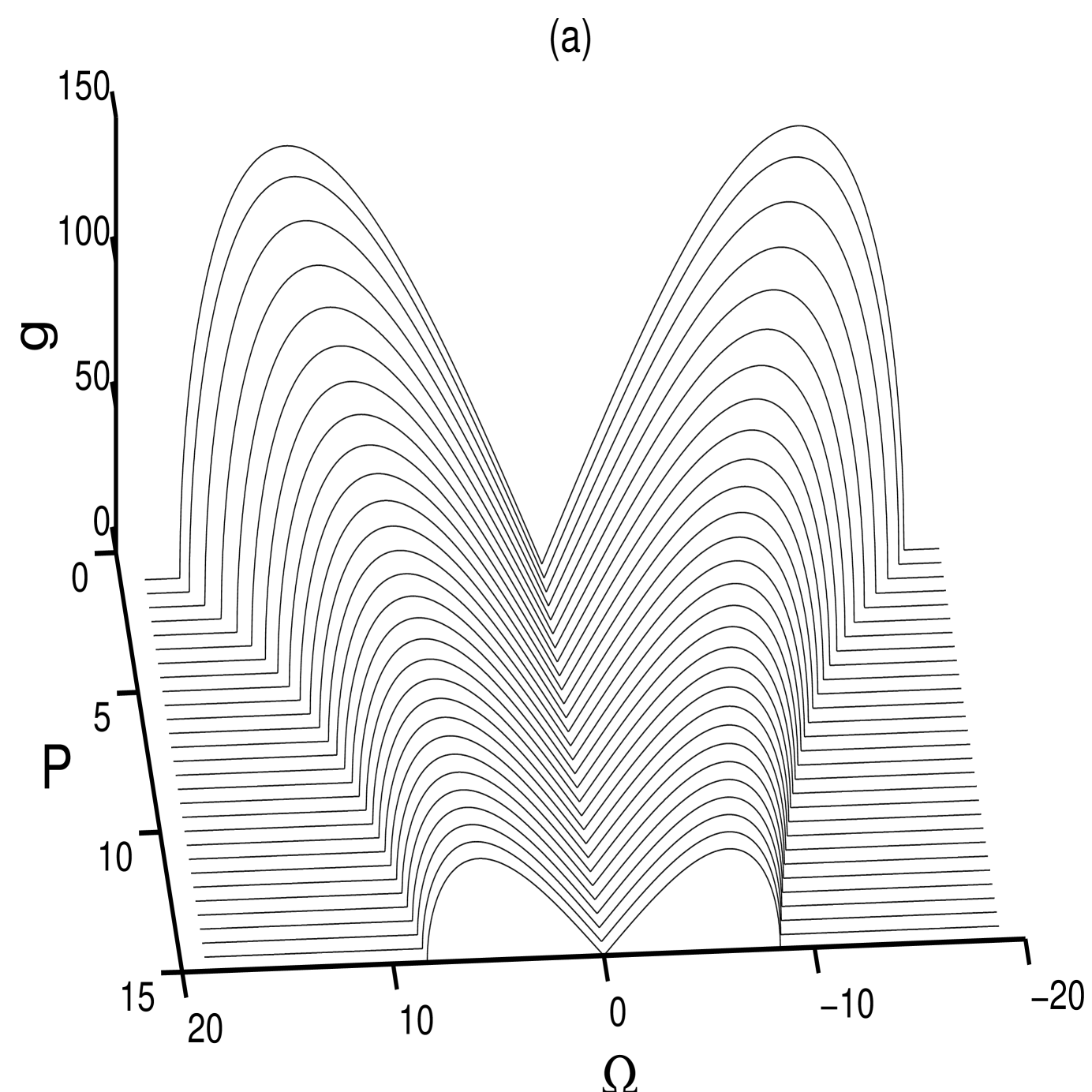
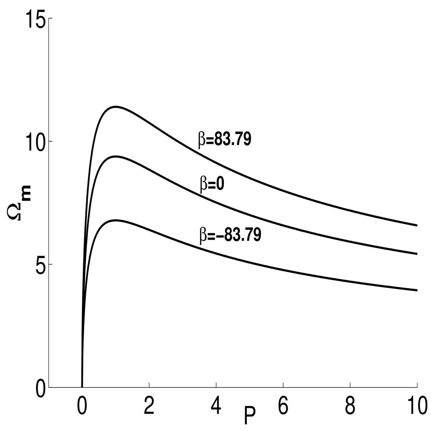
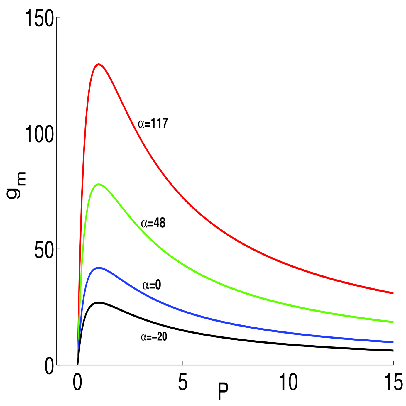
The instability is most efficient and reaches its maximum at when , where and . To examine the MI growth, we take a typical Cu:KNSBN crystal. Intermediate energy level is included in Cu:KNSBN crystal and photovoltaic field is in the direction of optic axis. At , crystal parameters are , , . The scaling parameter , and . We take three different values of , in particular, , and which corresponds to and respectively. Figure (1) depicts the MI gain spectrum as a function of perturbation frequency . The variation of with for three values of has been depicted in figure (2). Initially increases with the increase in the value of then decreases with the increase in . In order to examine the role played by on the growth of the instability, we have demonstrated in figure (3) the variation of maximum growth with the normalized beam power for three different value of . As expected, a higher value of enhances the growth of the instability. In conclusion, with the application of external electric field, it is possible to initiate modulation instability and control the growth of the instability in those media where MI was hitherto prohibited.
9 Conclusion
A brief review of some selected developments in the field of optical spatial solitons in PR media has been presented. Underlying mechanism responsible for the formation of solitons have been discussed for both single and two-photon PR media. Vector solitons, particularly, incoherently coupled solitons due to single photon and two-photon PR phenomena have been highlighted. Existence of some missing solitons pointed out. Modulation instability which is a precursor to soliton formation has been also considered. Important applications of PR solitons have been highlighted.
Acknowledgment
This work is supported by SAP programme of University Grants
Commsion (UGC), Government of India. One of the authors SK would like
to thank UGC for this.
References
- Hasegawa et al. [1973] A. Hasegawa and F. Tappert, Appl. Phys. Lett. 23, 142(1973).
- Agrawal et al. [1989] G. P. Agrawal, Academic Press, New York (1989).
- Anjan Biswas et al. [2006] A. Biswas and S. Konar; Non-Kerr Law Optical Solitons, CRC Press, New York (2006).
- Konar et al. [1994] S. Konar, A. Sengupta, J. Opt. Soc. Am. B 11, 1644(1994).
- Kivshar et al. [2001] Y.S. Kivshar and A. A. Sukhorukov, in: S. Trillo and W. Toruellas (Eds.), Spatial Solitons, Springer, New York, 2001, pp. 211-246.
- Medhekar et al. [1995] S.Medhekar, S.Konar and M.S.Sodha, Opt. Lett. 20, 2192(1995).
- Akhmediev et al. [1997] N. N. Akhmediev and A. Ankiewicz, Solitons:Nonlinear Pulses and Beams, Chapman and Hall, London, 1997.
- Y. S. Kivshar and G. P. Agrawal [2003] Y. S. Kivshar and G. P. Agrawal, Optical Solitons: From Fibers to Photonic Crystals, Academic Press, San Diogo, California, 2003.
- M.Segev and G.I.Stegeman [1998] M. Segev and G.I.Stegeman, Phys. Today 51, 42(1998).
- V.E.Zhakharov and A.B.Shabat [1972] V.E.Zhakharov and A.B.Shabat, Sov. Phys. JETP 34, 62(1972).
- M.J.Ablowitz and H.Segur [1981] M. J. Ablowitz and H.Segur, Studies in Applied Mathematics (SIAM), Philadelphia, 1981.
- G.A.Askaryan [1962] G. A. Askaryan, Sov. Phys.- JETP 15, 1088(1962).
- Zabusky et al. [1965] N.J. Zabusky and M. D. Kruskal, Phys. Rev. Lett. 15, 240(1965).
- Konar et al. [2014] S. Konar and A. Biswas, Optical Materials 35, 2581(2013).
- P.L.Kelly [1965] P. L. Kelly, Phys. Rev. Lett. 15, 1005(1965).
- E.L.Dawes and J.Marburge [1969 ] E. L. Dawes and J.Marburge, Phys. Rev. 179, 862(1969).
- M.Segev et al. [1992] M. Segev, B.Crosignani, A.Yariv and B.Fischer, Phys. Rev. Lett. 68, 923(1992).
- Duree et al. [1993] G. C. Duree, J. L. Sultz, G. J. Salamo, M. Segev, A. Yariv, B.Crosignani, P. Di Porto, E. J. Sharp, R. R. Neurgaonkar, Phys. Rev. Lett. 71, 533(1993).
- Iturbe-Castillo et al. [1994] M. D. Iturbe-Castillo, P. A.M. Aguilar, J. J.Sánchez-Mondragón, S.I.Stepanov, V. Vysloukh, Appl. Phys. Lett. 64, 408(1994).
- Segev et al. [1994] M. Segev, G. C. Valley, B. Crosignani, P. Di Porto, and A. Yariv, Phys. Rev. Lett. 73, 3211(1994).
- Christodoulides et al. [1995] D. N. Christodoulides and M. I. Carvalho, J. Opt. Soc.Am B 12, 1628(1995).
- M.F.Shih et al . [1996] M. F. Shih, P. Leach, M. Segev, M. H. Garrett, G.Salamo and G. C. Valley, Opt. Lett. 21, 324(1996).
- M.F.Shis et al. [1997 ] M. F. Shih, M.Segev and G.Salamo, Phys. Rev. Lett. 78, 2551(1997).
- Z.Chen et al. [1996 ] Z. Chen, M. Mitchell and M. Segev, Opt. Lett. 21, 716(1996).
- J.S.Aitchison et al. [1991 ] J. S. Aitchison, A. M. Weiner, Y. Silberberg, D. E. Leaird, M. K. Oliver, J. L. Jackel, and P. W. E. Smith, Opt. Lett. 16, 15(1991).
- S Lan et al. [1999] S. Lan, E. DelRe, Z. Chen, M. F. Shih and M. Segev, Opt. Lett. 24, 475(1999).
- S Lan et al. [1999] S. Lan, M. F. Shih, G. Mizell, J. A. Giordmaine, Z. Chen, C. Anastassiou, J. Martin and M. Segev, Opt. Lett. 24, 1145(1999).
- Tienman et al. [2008] M. Tiemann, J. Petter, T. Tschudi, Opt. Commun. 281, 175(2008).
- Tienman et al. [2008] M. Tiemann, T.Halfmann,T.Tschudi, Opt. Commun. 282, 3612(2009).
- Kuroda et al. [2002] K. Kuroda, in: Kazuo Kuroda (Eds.), Progress in Photorefractive Nonlinear Optics, Taylor and Francis, New York, 2002, pp.1-8.
- Gunter et al. [2006 ] P. Gunter and J.P.Huignard, in: P. Gunter and J. P. Huignard (Eds.), Photorefractive Materials and Their Applications 1, Springer Series in Optical Sciences, Vol 113, Springer, 2006, pp. 1-5.
- Z.Chen et al. [2006 ] Z. Chen, M. Segev and D. N. Christodoulides, Rep. Prog. Phys. 75, 086401(2012).
- W. Krolikowski et al. [2003] W. Krlikowski, B. Luther-Davies and C. Denz; IEEE J. QE 39, 3(2003).
- DelRe et al. [2009] E. DelRe and M. Segev, in: R. W. Boyd, S. G. Lukishova, Y.R. Shen (Eds.), Self-focusing: Past and Present; Fundamentals and Prospects, Topics in Applied Physics, Vol. 114, Springer-Verlag, New York, 2009, pp. 547-572.
- DelRe et al. [2009] E. DelRe, P. Di Porto, and B.Crosignani, Progress in Optics 53, 153 (2009).
- Yeh et al. [1993 ] P. Yeh; Introduction to photorefractive nonlinear optics, Wiley, 1993.
- E.DelRe et al. [1998] E. DelRe, B.Crosignani, M.Tamburrini, M.Segev, M. Mitchell, E. Refaeli, and A.J.Agranat, Opt. Lett. 23, 421(1998).
- Kukhtarev et al. [1979] N. V. Kukhtarev, V.B. Markov, S. G. Odulov, M. S. Soskin and V.L. Vinetskii, Ferroelectrics 22, 949(1979).
- Shih et al. [1999] Minh-Feng Shih and F.W. Sheu, Opt. Lett. 24, 1853(1999).
- F.W.Sheu et al. [2001] F. W.Sheu and M. F. Shih, J. Opt. Soc. Am. B 18, 785(2001).
- M.Segev et al. [1997] M. Segev and A.J. Agranat, Opt. Lett. 22, 1299(1997).
- Carvalho et al. [1996] M. I. Carvalho, S. R. Singh, D. N. Christodoulides, Opt. Commun. 124,642(1996).
- Shih et al. [1995] M. F. Shih, M. Segev, G.C. Valley, G. Salamo, B. Crosignani, P. Di Porto, Electron. Lett. 31, 826(1995).
- A.A.Zozulya [1995] A. A. Zozulya and D. Z. Anderson, Phys. Rev. A 51, 1520(1995).
- Saffman et al. [1998] M. Saffman and A. A. Zozulya, Opt. Lett. 23, 1579(1998).
- Valley et al. [1994] G. C. Valley, M. Segev, B. Crosignani, A. Yariv, M. M. Fejer and M. C. Bashaw, Phys. Rev. A 50, R4457(1994).
- Chen et al. [1997] Z. Chen, M. Segev, D. W. Wilson, R. E. Muller and P. D. Maker, Phys. Rev. Lett. 78, 2948(1997).
- Konar et al. [2011] S.Konar, Phys. Express 1, 139(2011).
- She et al. [1999] W. L. She, K. K. Lee and W. K. Lee, Phys. Rev. Lett. 83, 3182(1999).
- [50] V. Coda, M. Chauvet, F. Pettazzi, and E. Fazio, Electron. Lett. 42, 463(2006).
- F. Pettazzi et al. [2007] F. Pettazzi, M. Alonzo, M. Centini, A. Petris, V. I. Vlad, M. Chauvet, and E. Fazio, Phys. Rev. A 76, 063818(2007).
- E. DelRe et al. [2000] E. DelRe, M. Tamburrini, and A.J. Agranat, Opt. Lett. 25, 963(2000).
- E. DelRe et al. [2002] E. DelRe, B.Crosignani, E.Palange, and A.J. Agranat, Opt. Lett. 27, 2188(2002).
- A. D’Ercole et al. [2004] A. D’Ercole, E. Palange, E. DelRe, A. Ciattoni, B. Crosignani, and A.J. Agranat, Appl. Phys. Lett. 85, 2679(2004).
- Liu et al. [1999] J. S. Liu and K.Q. Lu, J. Opt. Soc. Am B 16, 550(1999).
- Segev et al. [1997] M. Segev, G. C. Valley, M.C. Bashaw, M. Taya and M. M. Fejer, J. Opt. Soc. Am. B 14, 1772(1997).
- Sturman et al. [1992] B. I. Sturman and V. M.Fridkin, The photovoltaic and photorefractive effects in non-centrosymmetric materials, Gordon and Breach, Philadelphia, 1992.
- Christodoulides et al. [1996] D.N. Christodoulides, S. R. Singh, M. I. Carvalho and M. Segev, Appl. Phys. Lett. 68, 1763(1996).
- Chen et al. [ 1996] Z. Chen, M. Segev, T. H. Coskun, D. N. Christodoulides, Opt. Lett. 21,1436 (1996).
- Chen et al. [1996 ] Z. Chen, M. Segev, T. H. Coskun, D. N. Christodoulides, Y.S. Kivshar and V. V. Afanasjev, Opt. Lett. 21, 1821(1996).
- Chen et al. [1996] Z. Chen, M. Segev, T. H. Coskun and D. N. Christodoulides, Opt. Lett. 21, 1436(1996).
- Zakery et al. [2004] A. Zakery and K.Keshavarz, J. Phys. D: Appl. Phys. 37, 3409(2004).
- Hou et al. [2001] C. Hou, Z.Zhou, B.Yuan and X.Sun, Appl. Phys. B 72, 191(2001).
- S.Konar et al. [2002] S. Shwetanshumala, N. Asif, S. Konar, A. Biswas, Optik 124, 229(2013).
- Konar et al. [2010] S. Konar and N. Asif, Phys. Scr. 81, 015401(2010).
- Asif et al. [2008] N. Asif, S. Shwetanshumala and S. Konar, Phys. Lett. A 372, 735(2008).
- Srivastava et al. [2009] S. Srivastava and S.Konar, Optics and Laser Technology 41, 419(2009).
- Konar et al. [2010 ] S.Konar, S. Shekhar and W.P.Hong, Optics and Laser Technology 42, 1294(2010).
- Lu et al. [2001] K.Q. Lu, Y.Zhan, T.Tang and B. Li, Phys. Rev. E 64, 056603(2001).
- Konar et al. [2007] S. Konar, S. Jana, S. Shwetanshumala, Opt. Commun. 273 , 324(2007).
- Carvalho et al. [1996 ] M. I. Carvalho, S. R. Singh, D. N. Christodoulides. R. I. Joseph, Phys. Rev. E 53, R53(1996).
- W. Ramadan et al. [2003] W. Ramadan, E. Fazio, A. Mascioletti, F. Inam, R. Rinaldi, A. Bosco, V. I.Vlad, A.Petris and M. Bertolotti, J. Opt. A: Pure and Appl. Opt. 5, S432(2003).
- Castro-Camus et al. [2003 ] E. Castro-Camus and L.F.Magana, Opt. Lett. 28 , 1129(2003).
- Hou et al. [2005 ] C. F. Hou, Y. B. Pei, Z. X. Zhou and X. D.Sun, Phys. Rev. A 71, 053817(2005).
- Zhang et al. [2009 ] G. Zhang, J.S. Liu, J. Opt. Soc. Am. B 26, 113(2009).
- Zhang et al. [2007 ] Y.Zhang, C.F.Hou and S.X. Dong, Chinese Physics 16, 159(2007).
- Zhan et al. [2010] K.Zhan, C.F. Hou, T.Hao, Y.Zhang, Phys. Lett. A 374, 1242(2010).
- S.Konar et al. [2002] S. Shwetanshumala, S.Jana and S.Konar, J. Electro. Waves and Appl. 20,2193 (2006).
- Benjamin et al. [1967] Benjamin T B and Feir J E J. Fluid Mech. 27, 417 (1967).
- Hong et al. [2008] W P Hong, S Shwetanshumala, S Konar, Optics Commun. 281, 5864 (2008).
- Bingham et al. [2009] R. Bingham and C. N. Lashmore, Journal of Plasma Physics 21, 51 (2009).
- Kasamatsu et al. [2006] K. Kasamatsu and Makoto Tsubota, Phys. Rev.A 74, 013617 (2006).
- Yulin et al. [2006] A.V. Yulin, D.V. Skryabin and A.G. Vladimirov, Optics Express 14, 12347 (2006).
- Joseph et al. [2010] A Joseph, K. Porsezian, P. Tchofo Dinda, Journal of Modern Optics, 57, 436 (2010).
- Yao et al. [2009] Min Yao, Shuangchun Wen, Dajun Lei, Journal of Modern Optics 56, 121(2009).
- Konar et al. [2010] S. Konar, S. Shekhar and S. Shwetanshumala, Opt. and Laser Tech. 42, 1276 (2010).
- Jisha et al. [2008] C. P. Jisha, V. C. Kuriakose and K. Porsezian, J. Opt. Soc. Am B 25, 674 (2008).
- Hong et al. [2002] W.P. Hong, Opt. Commun. 213,173 (2002).
- Jablan et al. [2007] M. Jablan, H. Buljan, O. Manela, G. Bartal and M.Segev, Opt. Exp. 15, 4623 (2007).
- Shwetanshumala et al. [2011] S. Shwetanshumala and S. Konar, Phys. Scripta 83, 025401 (2011).
- Jeng et al. [2009] C.C. Jeng, Y. Y. Lin, R.C. Hong and R. K. Lee, Phys Rev Letts . 102, 153905 (2009).