Workflow Partitioning and Deployment on the Cloud using Orchestra
Abstract
Orchestrating service-oriented workflows is typically based on a design model that routes both data and control through a single point – the centralised workflow engine. This causes scalability problems that include the unnecessary consumption of the network bandwidth, high latency in transmitting data between the services, and performance bottlenecks. These problems are highly prominent when orchestrating workflows that are composed from services dispersed across distant geographical locations. This paper presents a novel workflow partitioning approach, which attempts to improve the scalability of orchestrating large-scale workflows. It permits the workflow computation to be moved towards the services providing the data in order to garner optimal performance results. This is achieved by decomposing the workflow into smaller sub workflows for parallel execution, and determining the most appropriate network locations to which these sub workflows are transmitted and subsequently executed. This paper demonstrates the efficiency of our approach using a set of experimental workflows that are orchestrated over Amazon EC2 and across several geographic network regions.
Index Terms:
Service-oriented workflows, orchestration, partitioning, computation placement analysis, deploymentI Introduction
Service workflows represent the automation of services during which data is passed between the services for processing.
Typically, workflows are orchestrated based on a centralised design model that provides control over the workflow, supports process automation, and encapsulates the workflow logic in a central location at which its execution takes place.
There are several languages used to describe service workflows such as the Business Process Execution Language (BPEL) [1], which has been accepted as a standard service orchestration language.
The Simple Conceptual Unified Flow Language (SCUFL) is an example of a language for specifying large-scale workflows such as those seen in scientific applications [2].
It is supported by the Taverna workbench and is typically executed using a workflow engine known as Freefluo [3].
However, workflow management systems of this kind route both data and control through a single point, which causes scaling problems including the unnecessary consumption of network bandwidth, high latency in transmitting data between the services, and performance bottlenecks.
Scientific workflows can be composed from services that may be dispersed across distant geographical locations.
Determining the most appropriate location at which to execute the workflow logic becomes difficult as the number of geographically distributed services increases.
Most workflow management approaches rely on data placement strategies that attempt to move the data closer to locations at which the computation takes place [4, 5, 6, 7, 8].
This involves a set of activities related to data transfer, staging, replication, management and allocation of resources.
However, the distribution of large portions of data between the services and across long distances through the centralised engine can affect the data transfer rate, increase the execution time, risk overwhelming the storage resources at execution sites, and degrade the overall workflow performance.
Recent research efforts show interest in using Infrastructure as a Service (IaaS) clouds that provide on-demand computational services to support cost-efficient workflow management [9, 10], but do not examine how the geographical location of services can affect the workflow performance.
The principal contribution of this paper is a partitioning approach that permits a workflow to be decomposed into smaller sub workflows for parallel execution on the cloud.
It determines the most appropriate locations to which these sub workflows are transmitted and subsequently executed.
Unlike existing approaches that depend on data placement, our approach permits the workflow computation to be moved closer to the services providing the data.
Through adopting this approach, distributed workflow engines can collaborate together to execute the overall workflow.
Each engine is carefully selected to execute a smaller part of the workflow within short network distance to the services.
For instance, an engine may be selected if it is hosted in the same network region where the services are resident in a cloud-based environment.
Our approach relies on collecting Quality of Service (QoS) information that represents the network delay (e.g. network latency and bandwidth) with a combination of heuristics to select the nearest engines to the services.
It is hypothesised that this improves the workflow performance by reducing the overall data transfer among the services.
Previously we created a distributed architecture for executing service workflows [11],
which relies on a high-level language [12] for specifying workflows.
However, the published articles relating to these works do not discuss our workflow partitioning approach.
This paper presents a refined design of our architecture, evaluates our approach accordingly, and compares it to existing works.
In order to investigate the benefits of our approach, we use a set of experimental workflows that are executed over Amazon EC2 and across several geographic network regions.
These workflows are based on dataflow patterns that are commonly used to compose large-scale scientific workflows [13], which include the pipeline, distribution and aggregation patterns.
The rest of this paper is organised as follows: Section II presents a simple workflow example that is used throughout the paper to explain our approach. Section III presents our workflow partitioning approach. Section IV discusses a workflow partitioning example. Section V discusses and evaluates our approach implementation. Section VI reviews related works. Finally, section VII summarises our work achievements and states future research directions.
II Workflow Example
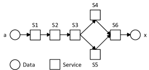
Our approach relies on a new high-level functional data coordination language for the specification of workflows known as Orchestra. It separates the workflow logic from its execution, and permits a workflow architect (e.g. scientist, engineer) to design a workflow without knowledge of how it is executed. Orchestra allows a workflow to be composed as a Directed Acyclic Graph (DAG) that supports common dataflow patterns, and provides succinct abstractions for defining the services and coordinating the dataflow between them. This section provides a simple workflow example that is used throughout this paper to explain our approach. Figure 1 shows its structure, where the input a is used to invoke service S1, which produces an output that is used to invoke S2 whose output is then passed to S3. The output of S3 is used to invoke both S4 and S5, whose outputs are used as inputs for S6, which produces the final workflow output x.
Listing 1 presents the specification of this workflow using our language where the workflow name example is defined in line 1 using the workflow keyword.
The description keyword is used to declare identifiers for a service description documents, each of which can be located using a URL through lines 2-7.
This permits the compiler to retrieve information about the services, their operations and associated types for syntax analysis.
The service keyword is used to declare the service identifiers s1, s2, s3, s4, s5 and s6 through lines 8-13.
Similarly, the service ports p1, p2, p3, p4, p5 and p6 are declared using the port keyword through lines 14-19.
The input and output keywords define the workflow interface, which provides an input a and an output x of the same type through lines 20-23.
Our language supports common dataflow patterns by specifying service invocations and the data passed to them. Each service invocation consists of a port identifier and an associated operation separated by a dot symbol. The output of a particular service invocation can be associated with an identifier, or passed directly to another service invocation to create a service composition. The arrow symbol indicates the direction of the data to or retrieved from service invocations. The following dataflow patterns are specified in listing 1:
-
•
Pipeline pattern: This pattern is used for chaining several services together, where the output of a particular service is used as an input to invoke another. For instance, a is used to invoke p1.Op1 whose result is passed directly to p2.Op2, which in turn produces a result that is passed to p3.Op3 through lines 24-26.
-
•
Data distribution pattern: This pattern is used to transmit several identical copies of a particular service output to multiple services. For instance, the invocation result of p3.Op3 is used to invoke both p4.Op4 and p5.Op5 in line 27. This finite sequence of invocations is the simplest parallel data structure in our language where each invocation is executed concurrently.
-
•
Data aggregation pattern: The results of several service invocations may be passed as individual input parameters to one particular service using this pattern. For instance, the results of both p4.Op4 and p5.Op5 are used as input parameters par1 and par2 respectively to invoke operation p6.Op6 through lines 28-29. Finally, x represents the result of p6.Op6 in line 30.
III Overview of Approach
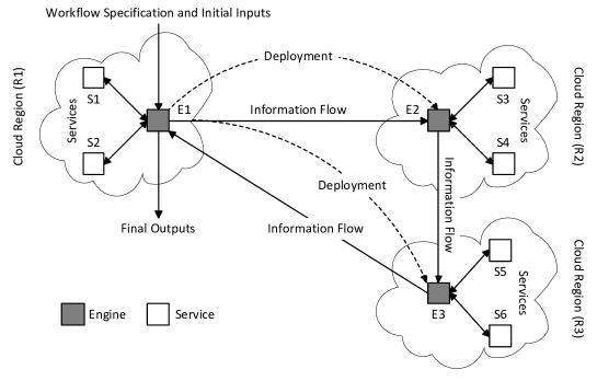
In order to realise our approach we created a fully distributed orchestration architecture. Unlike existing orchestration technology where the locus of control is represented by a centralised engine that holds the decision logic of the workflow, the notion of a single locus of control does not exist in our architecture. During the workflow execution, the decision logic can be found at one or several engines. Figure 2 shows an overview of our architecture that consists of distributed workflow engines. These engines collaborate together to complete the workflow execution. For instance, a workflow engine may be responsible for analysing and partitioning a workflow specification into smaller sub workflows. These sub workflows may be deployed onto remote engines for execution. Each engine then exploits connectivity to a group of services by invoking them or composing them together, retrieving invocation results, and forwarding relevant information to remote engines as necessary. The following sections discuss the compilation and partitioning of a workflow specification, deployment of sub workflows and monitoring their execution.
III-A Compilation
Our approach uses a recursive descent compiler that analyses a workflow specification to ensure its correctness. It does not generate machine code representation from the workflow specification, but constructs an executable graph-based data structure instead, which consists of vertices that represent service invocations with edges between them as data dependencies. The components of this data structure can be distributed to remote workflow engines at arbitrary network locations. This permits a workflow to be maintained upon its distribution such that it can be refactored for optimisation purposes during run-time.
III-B Partitioning
Our workflow partitioning approach consists of several phases that include workflow decomposition, placement analysis, and composition of sub workflows.
III-B1 Decomposition of a workflow
This phase decomposes a workflow graph into smaller data structures that represent sub workflows. Hence, we created a traverser that explores the workflow graph to gain insight about its complexity and detect its intricate parallel parts. It obtains information about the workflow inputs, outputs, services, invocations, and associated types. This information is used to detect the maximum number of smallest sub workflows, each of which consists of a single invocation, or multiple sequential invocations to the same service if a data dependency exists between them.
III-B2 Placement analysis
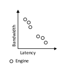
Once a workflow has been decomposed by the traverser, placement analysis are performed to determine the most appropriate engines that may execute the sub workflows. This phase involves the following activities, which are illustrated in figure 3.
-
•
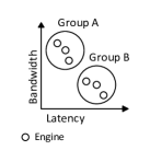
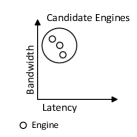
Discovery and clustering of engines: This activity identifies a set of available engines that may execute the sub workflows111This paper does not focus on mechanisms to discover the engines.. For each sub workflow, these engines are organised into groups using the k-means clustering algorithm, and according to QoS metrics that represent the network delay, which include the network latency and bandwidth between each engine and the single service endpoint in the sub workflow.
-
•
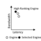
Elimination of inappropriate engines: Upon clustering, groups containing inappropriate engines are eliminated from further analysis. This is achieved by identifying the engines with metrics that are worse than those of engines in other groups.
-
•
Ranking and selection of engines: Each remaining candidate engine is ranked by predicting the transmission time between the engine and the service endpoint using:
(1) where is the transmission time, and are the latency and bandwidth between the engine and the service respectively, and is the size of the input that is used to invoke the service. Consequently, an engine with the shortest transmission time is selected.
III-B3 Composition of sub workflows
The sub workflows may be combined together if the same engine is selected to execute them. This involves introducing directed edges between them wherever a data dependency exists. Consequently, the composite workflows are encoded using the same language as used to specify the entire workflow. During the recoding, relevant information such as the workflow inputs, outputs, service invocations, data dependencies and type representations are all captured, and associated with the composite workflows to make each a self contained stand-alone workflow specification.
III-C Deployment and Monitoring
Our approach uses the knowledge about the network condition with a combination of heuristics for initially deploying the workflow. Each composite workflow specification is dispatched to a designated engine, which compiles and executes it immediately. This deployment process is transparent and does not require any user intervention. Upon deployment, real-time distributed monitoring may be used to guide the workflow toward optimal performance. This is achieved by detecting the network condition periodically and performing further placement analysis. Our approach uses the application layer capabilities to deliver useful information about the network condition in terms of network latency and bandwidth. For instance, an engine measures the latency by computing the average round-trip time of a series of HTTP HEAD requests issued to a service. Similarly, the bandwidth is measured using the request completion time and the response message size.
IV Workflow Partitioning Example
This section presents an arbitrary workflow partitioning scenario based on the workflow example in figure 1, where the workflow is decomposed into smaller sub workflows as shown in figure 4.
Each sub workflow consists of a single service invocation, which requires one or more inputs and produces a single output.
Upon selecting appropriate engines to execute the sub workflows, they may be combined together to form composite workflows.
During their composition, they are analysed to detect any external dependency between them where an output of a sub workflow is required as an input for another.
Upon detecting an external dependency, it is replaced by a direct service composition between the service endpoint that produces the data and the one that requires it in the composite workflow.
The intermediate data between the services may be represented in the composite workflow as output data when it is required for executing other composite workflows.


Listing 2 shows a computer generated specification of the composite workflow shown in figure 5. This specification is executed by an engine that is deployed closer to services S1 and S2 as shown in figure 2. It shows a universally unique identifier that is specified using the uid keyword in line 2. This identifier is generated to distinguish the workflow from others with the same name. The engine keyword declares a remote engine identifier in line 3. The identifiers relating to the services are all declared through lines 4-9. The workflow interface is defined through lines 10-13. The input a is used to invoke p1.Op1, whose output is passed to p2.Op2 that produces c. Finally, the workflow output is forwarded to e2 to perform further computation using the forward keyword.

Listing 3 shows the specification of the second workflow which is shown in figure 6. This specification is executed closer to s3 and s4 by engine e2 as shown in figure 2, and upon the availability of the workflow input c.

Listing 4 shows the specification of the workflow in figure 7, where p5.Op5 and p6.Op6 are invoked consecutively. Finally, the workflow output x is forwarded to engine e1, which acts as a data sink for the workflow outputs. Typically, this engine is the initial engine that partitioned the workflow and deployed it.

V Implementation and Evaluation
The overall implementation is based on Java and wrapped as a web service package that can be deployed on any physical or virtual machine. It relies upon the Java Runtime Environment (JRE) and Apache Tomcat server. We have designed a set of experimental workflows to evaluate our approach, each of which is specified based on a particular dataflow pattern. These workflows consist of a different number of services that are deployed on Amazon EC2, and across several network locations in geographical regions to explore the scalability of our approach. They are categorised into continental and inter-continental workflows.
V-A Configuration
V-A1 Continental workflows
These workflows consist of services hosted in the same network region such as N. Virginia (us-east-1) over Amazon EC2. They are orchestrated in the following configurations:
-
•
Centralised orchestration (local): The workflow is executed by a workflow engine that is deployed in the same network region where the services are resident as shown in figure 8.
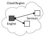
Figure 8: Centralised orchestration (local). -
•
Centralised orchestration (remote): The workflow is executed by a workflow engine that is deployed in a different network region than the one where the services are resident such as N. California (us-west-1). This configuration is shown in figure 9.
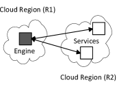
Figure 9: Centralised orchestration (remote). -
•
Distributed orchestration: The workflow is executed using our approach by distributed workflow engines, which are deployed in the same network region where the services are resident as shown in figure 10.
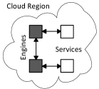
Figure 10: Distributed orchestration of continental services.
V-A2 Configuration of inter-continental workflows
These workflows consist of services that are distributed across N. Virginia (us-east-1), N. California (us-west-1), Oregon (us-west-2) and Ireland (eu-west-1). They are orchestrated in the following configurations:
-
•
Centralised orchestration: The workflow is executed by a centralised engine that is deployed at an arbitrary network location as shown in figure 11.
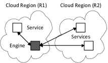
Figure 11: Centralised orchestration. -
•
Distributed orchestration: The workflow is executed using our approach by distributed engines that are dispersed over several network regions as shown in figure 12.
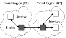
Figure 12: Distributed orchestration.
V-B Analysis
The completion time for each workflow is recorded in seconds, and the size of total communicated data in MB. Each workflow is executed using 21 inputs to emulate the data increase in each run, and for 20 times (420 runs in total). The mean speedup rate is computed using:
| (2) |
where and are the average workflow completion times using centralised and distributed orchestration respectively.
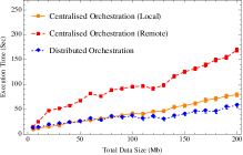
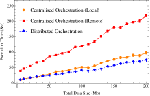
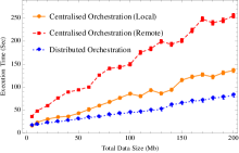
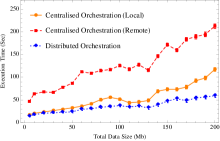
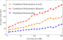
V-B1 Analysis of continental workflows
There are a number of observations that can be derived from our experimental results.
Firstly, executing a continental workflow by a centralised engine within the same region provides better performance compared to executing the same workflow by a centralised engine that resides in a remote region.
This is evident in all continental workflows as shown in figure 13.
Secondly, executing a continental workflow that consists of a small number of services using distributed orchestration may not provide significant performance improvement over local centralised orchestration as shown in figures 13a, 13b, and 13c.
This is because introducing more engines involves the communication of additional intermediate copies of data between them, which may increase the workflow execution time.
Finally, distributed orchestration becomes more useful as the number of services increases according to figures 13d, 13e, and 13f.
Tables I, and II summarise the results where N is the number of services, and are the mean speedup rates for distributed orchestration compared to local and remote centralised orchestration respectively.
| Pattern | N | ||
|---|---|---|---|
| Pipeline | 8 | 1.13 | 2.60 |
| Distribution | 8 | 1.18 | 2.69 |
| Aggregation | 8 | 1.25 | 3.23 |
| Pattern | N | ||
|---|---|---|---|
| Pipeline | 16 | 1.59 | 3.19 |
| Distribution | 16 | 1.43 | 3.45 |
| Aggregation | 16 | 1.93 | 3.28 |
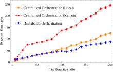
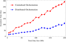
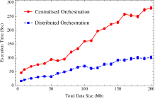
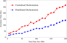
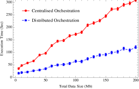
V-B2 Analysis of inter-continental workflows
Our distributed orchestration approach provides significant performance improvement for all inter-continental workflows as shown in figure 14. Firstly, a centralised engine may take considerable amount of time to execute a workflow due to high latency and low bandwidth between itself and the services. Secondly, executing a workflow using distributed engines reduces the overall execution time as the data size increases. This is because several parts of the workflow logic are executed in parallel at the nearest locations to the services, which improves the response times between the engines and the services. Finally, the time for transferring the intermediate data between the engines may be affected because of the change in the network condition, but it does not degrade the overall workflow performance. Table III provides the workflow results.
| Pattern | N | |
|---|---|---|
| Pipeline | 16 | 2.69 |
| Distribution | 16 | 2.54 |
| Aggregation | 16 | 1.97 |
V-B3 Analysis of an inter-continental end-to-end workflow
Although this paper has focused primarily on evaluating our approach based on common dataflow patterns, it is essential to demonstrate its efficacy based on an end-to-end workflow application that combines all these patterns together. Hence, we created a workflow that consists of 16 services which are distributed across multiple regions. Figure 15 shows the overall results where the mean speedup is 2.68. The final outputs of all inter-continental workflows are obtained from the services, and stored on machines that host the engines which obtained the outputs.
VI Related Works
VI-A Workflow Management Systems
Pegasus [14] is a notable workflow management system that relies on a centralised engine for scheduling distributed workflow tasks. Our approach is based on a distributed design model that permits the workflow partitions to be executed without prior scheduling. Each sub workflow is executed automatically as soon as the data that is required for its execution is available from other sources. Condor [15] leverages resource machines for executing distributed tasks using batch processing. These tasks are specified manually by the user, and pre-knowledge about the machines and the condition of the network is required. Our architecture handles the partitioning and mapping of workflows onto machines automatically by collecting information about the network condition, and performing placement analysis. Triana [16] permits a workflow to be distributed across machines, and supports control flows by associating coordination logic with workflow scripts. Control flows are unnecessary in our approach as it is relies on a dataflow language that avoids loops and control structures in the workflow. Kepler [17] is based on actor-oriented modelling that permits a workflow to be composed using actors which communicate through well-defined interfaces. However, it does not support decentralised execution of workflows.
VI-B Dataflow Optimisation Architectures
The Circulate approach [18], [19] supports data distribution in the workflow using proxy components, which may be deployed closer to the services. These proxies exploit connectivity to the services, and route the data in the workflow to locations where they are required. However, this architecture relies on a centralised flow mechanism to facilitate the collaboration between proxies, and there seems to be no automated mechanism for partitioning the workflow. The Flow-based Infrastructure for Composing Autonomous Services (FICAS) [20] supports service composition by altering the service interfaces to enable peer-to-peer collaboration. Our approach does not require modifying the implementation of services. Data processing techniques built on MapReduce [21] may be suitable for a wide range of problems, but are inadequate for executing workflows. For instance, a workflow can be composed using a series of MapReduce jobs [22], but this requires passing the entire state and data from one job to the next which degrades performance. Dryad [23] supports executing distributed processing tasks, but it does not provide any mechanism to rearrange the workflow structure for optimisation purposes. Furthermore, the distributed workflow parts must be specified manually. Our approach automatically generates the distributed sub workflow specifications.
VI-C Workflow Scheduling Approaches
There are many scheduling heuristics that attempt to solve the workflow mapping problem such as HEFT [24], Min-Min [25], MaxMin and MCT [26], but these works are directed at grid-based workflow applications. Several other heuristic methods were proposed and compared in [27]. Partitioning is proposed for provisioning resources into execution sites in [28] and [29], but not for decomposing the actual dataflow graph. In [30] and [31], a strategy is discussed where the workflow tasks are mapped onto grid sites. This is achieved by assigning weights to the vertices and edges in the workflow graph by predicting the execution time for each task, and the time for transferring data between the resources. Each task is then mapped onto a resource that provides the earliest expected time to complete its execution. However, the time for executing a service operation cannot be predicted efficiently in a service-oriented environment as it depends on the application logic, and the underlying protocols and infrastructure.
VII Conclusion
Centralised service orchestration presents significant scalability problems as the number of services and the size of data involved in the workflow increases. These problems include the unnecessary consumption of the network bandwidth, high latency in transmitting data between the services, and performance bottlenecks. This paper has presented and evaluated a novel workflow partitioning approach that decomposes a workflow into smaller sub workflows, which may then be transmitted to appropriate locations at which their execution takes place. These locations are carefully determined using a heuristic technique that relies on the knowledge of the network condition. This permits the workflow logic to be executed within short geographical distance to the services, which improves the overall workflow performance. Future work will focus on real-time distributed monitoring, and re-deployment of executing sub workflows to adapt to dynamic changes in the execution environment.
References
- [1] T. Andrews, F. Curbera, H. Dholakia, Y. Goland, J. Klein, F. Leymann, K. Liu, D. Roller, D. Smith, S. Thatte, et al., “Business process execution language for web services,” 2003.
- [2] G. Juve, A. L. Chervenak, E. Deelman, S. Bharathi, G. Mehta, and K. Vahi, “Characterizing and profiling scientific workflows,” Future Generation Computer Systems, vol. 29, no. 3, pp. 682–692, 2013.
- [3] T. M. Oinn, M. Addis, J. Ferris, D. Marvin, M. Senger, R. M. Greenwood, T. Carver, K. Glover, M. R. Pocock, A. Wipat, and P. Li, “Taverna: a tool for the composition and enactment of bioinformatics workflows,” Bioinformatics, vol. 20, no. 17, pp. 3045–3054, 2004.
- [4] S. Bharathi and A. Chervenak, “Data staging strategies and their impact on the execution of scientific workflows,” in Proceedings of the Second International Workshop on Data-aware Distributed Computing, DADC ’09, (New York, NY, USA), ACM, 2009.
- [5] A. L. Chervenak, E. Deelman, M. Livny, M. Su, R. Schuler, S. Bharathi, G. Mehta, and K. Vahi, “Data placement for scientific applications in distributed environments,” in 8th IEEE/ACM International Conference on Grid Computing (GRID 2007), September 19-21, 2007, Austin, Texas, USA, Proceedings, pp. 267–274, 2007.
- [6] K. Ranganathan and I. T. Foster, “Simulation studies of computation and data scheduling algorithms for data grids,” Journal of Grid Computing, vol. 1, no. 1, pp. 53–62, 2003.
- [7] T. Kosar and M. Livny, “A framework for reliable and efficient data placement in distributed computing systems,” Journal of Parallel and Distributed Computing, vol. 65, no. 10, pp. 1146–1157, 2005.
- [8] D. Thain, J. Basney, S. Son, and M. Livny, “The kangaroo approach to data movement on the grid,” in 10th IEEE International Symposium on High Performance Distributed Computing (HPDC-10 2001), 7-9 August 2001, San Francisco, CA, USA, pp. 325–333, 2001.
- [9] E. Deelman, G. Singh, M. Livny, G. B. Berriman, and J. Good, “The cost of doing science on the cloud: the montage example,” in Proceedings of the ACM/IEEE Conference on High Performance Computing, SC 2008, November 15-21, 2008, Austin, Texas, USA, p. 50, 2008.
- [10] C. Hoffa, G. Mehta, T. Freeman, E. Deelman, K. Keahey, G. B. Berriman, and J. Good, “On the use of cloud computing for scientific workflows,” in Fourth International Conference on e-Science, e-Science 2008, 7-12 December 2008, Indianapolis, IN, USA, pp. 640–645, 2008.
- [11] W. Jaradat, A. Dearle, and A. Barker, “An architecture for decentralised orchestration of web service workflows,” in Web Services (ICWS), 2013 IEEE 20th International Conference on, pp. 603–604, IEEE, 2013.
- [12] W. Jaradat, A. Dearle, and A. Barker, “A dataflow language for decentralised orchestration of web service workflows,” in Services (SERVICES), 2013 IEEE Ninth World Congress on, pp. 13–20, IEEE, 2013.
- [13] A. Barker and J. Van Hemert, “Scientific workflow: a survey and research directions,” in Proceedings of the 7th international conference on Parallel processing and applied mathematics, pp. 746–753, Springer-Verlag, 2007.
- [14] E. Deelman, G. Singh, M. Su, J. Blythe, Y. Gil, C. Kesselman, G. Mehta, K. Vahi, G. B. Berriman, J. Good, A. C. Laity, J. C. Jacob, and D. S. Katz, “Pegasus: A framework for mapping complex scientific workflows onto distributed systems,” Scientific Programming, vol. 13, no. 3, pp. 219–237, 2005.
- [15] M. J. Litzkow, M. Livny, and M. W. Mutka, “Condor - A hunter of idle workstations,” in Proceedings of the 8th International Conference on Distributed Computing Systems, San Jose, California, USA, June 13-17, 1988, pp. 104–111, 1988.
- [16] I. J. Taylor, M. S. Shields, I. Wang, and R. Philp, “Distributed P2P computing within triana: A galaxy visualization test case,” in 17th International Parallel and Distributed Processing Symposium (IPDPS 2003), 22-26 April 2003, Nice, France, CD-ROM/Abstracts Proceedings, p. 16, 2003.
- [17] B. Ludäscher, I. Altintas, C. Berkley, D. Higgins, E. Jaeger, M. B. Jones, E. A. Lee, J. Tao, and Y. Zhao, “Scientific workflow management and the kepler system,” Concurrency and Computation: Practice and Experience, vol. 18, no. 10, pp. 1039–1065, 2006.
- [18] A. Barker, J. B. Weissman, and J. I. van Hemert, “Reducing data transfer in service-oriented architectures: The circulate approach,” IEEE Transactions on Services Computing, vol. 5, no. 3, pp. 437–449, 2012.
- [19] A. Barker, J. B. Weissman, and J. I. van Hemert, “The Circulate architecture: avoiding workflow bottlenecks caused by centralised orchestration,” Cluster Computing, vol. 12, no. 2, pp. 221–235, 2009.
- [20] W. D. Liu, A distributed data flow model for composing software services. PhD thesis, Stanford University, 2003.
- [21] J. Dean and S. Ghemawat, “Mapreduce: simplified data processing on large clusters,” Communications of the ACM, vol. 51, no. 1, pp. 107–113, 2008.
- [22] J. Cohen, “Graph twiddling in a mapreduce world,” Computing in Science and Engineering, vol. 11, no. 4, pp. 29–41, 2009.
- [23] M. Isard, M. Budiu, Y. Yu, A. Birrell, and D. Fetterly, “Dryad: distributed data-parallel programs from sequential building blocks,” in Proceedings of the 2007 EuroSys Conference, Lisbon, Portugal, March 21-23, 2007, pp. 59–72, 2007.
- [24] H. Topcuoglu, S. Hariri, and M. Wu, “Performance-effective and low-complexity task scheduling for heterogeneous computing,” IEEE Transactions on Parallel Distributed Systems, vol. 13, no. 3, pp. 260–274, 2002.
- [25] J. Blythe, S. Jain, E. Deelman, Y. Gil, K. Vahi, A. Mandal, and K. Kennedy, “Task scheduling strategies for workflow-based applications in grids,” in 5th International Symposium on Cluster Computing and the Grid (CCGrid 2005), 9-12 May, 2005, Cardiff, UK, pp. 759–767, 2005.
- [26] T. D. Braun, H. J. Siegel, N. Beck, L. Bölöni, M. Maheswaran, A. I. Reuther, J. P. Robertson, M. D. Theys, B. Yao, D. A. Hensgen, and R. F. Freund, “A comparison of eleven static heuristics for mapping a class of independent tasks onto heterogeneous distributed computing systems,” Journal of Parallel and Distributed Computing, vol. 61, no. 6, pp. 810–837, 2001.
- [27] R. Sakellariou and H. Zhao, “A hybrid heuristic for DAG scheduling on heterogeneous systems,” in 18th International Parallel and Distributed Processing Symposium (IPDPS 2004), CD-ROM / Abstracts Proceedings, 26-30 April 2004, Santa Fe, New Mexico, USA, 2004.
- [28] S. Kumar, S. K. Das, and R. Biswas, “Graph partitioning for parallel applications in heterogeneous grid environments,” in 16th International Parallel and Distributed Processing Symposium (IPDPS 2002), 15-19 April 2002, Fort Lauderdale, FL, USA, CD-ROM/Abstracts Proceedings, 2002.
- [29] C. Lin, C. Shih, and C. Hsu, “Adaptive dynamic scheduling algorithms for mapping ongoing m-tasks to pr grid,” Journal of Information Science and Engineering, vol. 26, no. 6, pp. 2107–2125, 2010.
- [30] R. Duan, R. Prodan, and T. Fahringer, “Run-time optimisation of grid workflow applications,” in 7th IEEE/ACM International Conference on Grid Computing (GRID 2006), September 28-29, 2006, Barcelona, Spain, Proceedings, pp. 33–40, 2006.
- [31] M. Wieczorek, R. Prodan, and T. Fahringer, “Scheduling of scientific workflows in the ASKALON grid environment,” SIGMOD Record, vol. 34, no. 3, pp. 56–62, 2005.