Negative Tunneling Magneto-Resistance in Quantum Wires with Strong Spin-Orbit Coupling

Seungju Han Department of Physics, Korea University, Seoul 136-701, Korea    Llorenç Serra IFISC (CSIC-UIB) and Department of Physics, University of the Balearic Islands E-07122 Palma de Mallorca, Spain    Mahn-Soo Choi Department of Physics, Korea University, Seoul 136-701, Korea
Abstract

We consider a two-dimensional magnetic tunnel junction of the FM/I/QW(FM+SO)/I/N structure, where FM, I and QW(FM+SO) stand for a ferromagnet, an insulator and a quantum wire (QW) with both magnetic ordering and Rashba spin-orbit (SOC), respectively. The tunneling magneto-resistance (TMR) exhibits strong anisotropy and switches sign as the polarization direction varies relative to the QW axis, due to interplay among the one-dimensionality, the magnetic ordering, and the strong SOC of the QW. The results may provide a possible explanation for the sign-switching anisotropic TMR recently observed in the LaAlO3/SrTiO3 interface.

The magnetic tunneling junction (MTJ) consisting of two ferromagnetic electrodes (FM) separated by a thin insulating barrier (I) is a prototype structure in the rapidly developing field of spintronics Wolf et al. (2001). The tunneling magneto-resistance (TMR), depending on the relative magnetic polarization of the two FMs, is a key issue not only for the spintronic applications but also for the study of fundamental magnetic properties Moodera et al. (2010); Miyazaki and Tezuka (1995). Due to the spin selection rule the TMR, if any, is typically positive. Two exceptional cases have been known. One involves magnetic impurities in the tunnel barriers and is not surprising. The other (more important) case is associated with the resonant tunneling and spin-dependent interfacial phase shift in double-barrier FM/I/N/I/FM structures, where N represents a non-magnetic normal metal Tsymbal et al. (2003); Sahoo et al. (2005); Cottet et al. (2006); Cottet and Choi (2006); Yuasa et al. (2002).

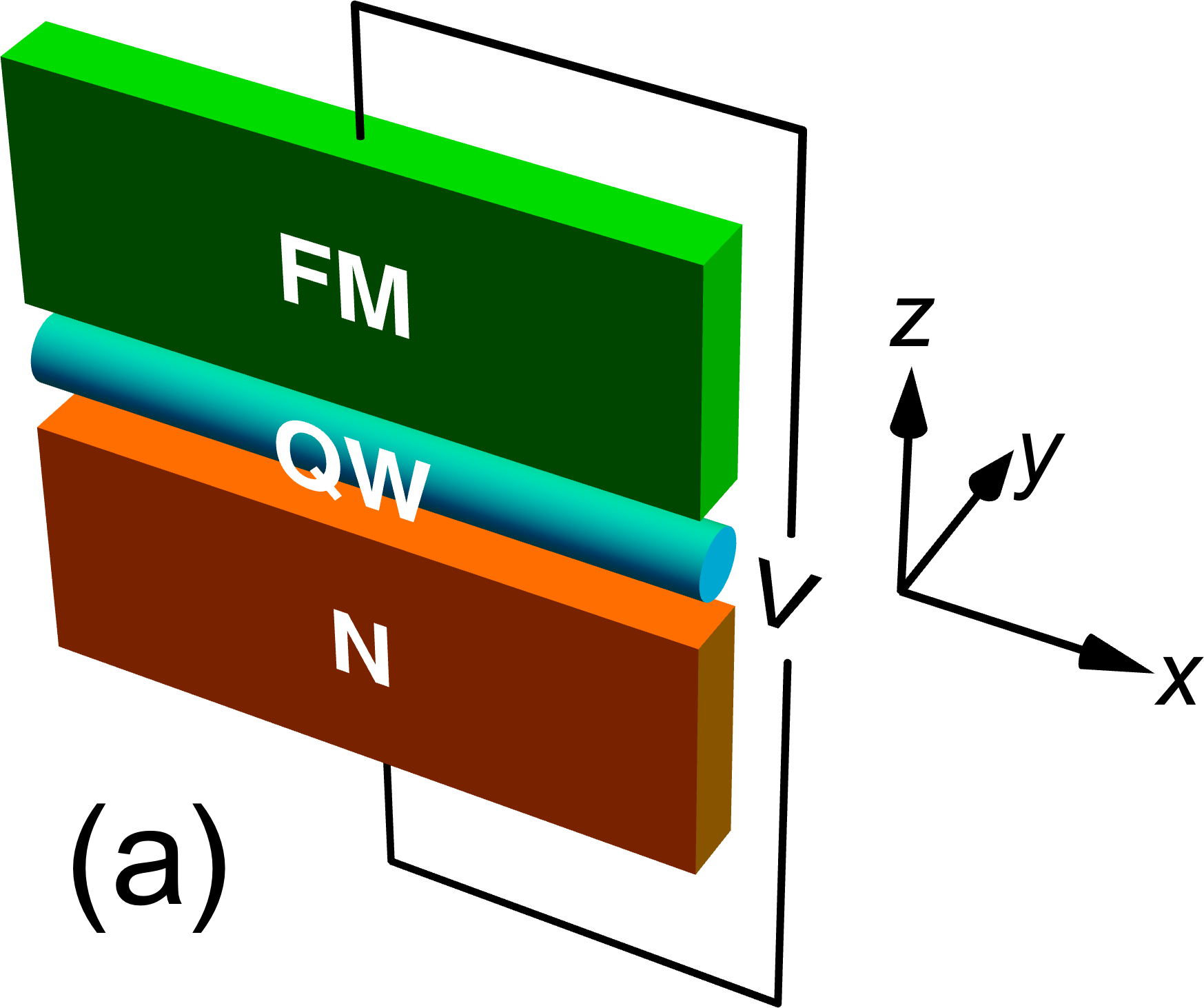
In this work we explore another non-trivial example of negative TMR in a two-dimensional (2D) double-barrier MTJ of the FM/I/QW(FM+SO)/I/N structure [see Fig. 1 (a)], where QW(FM+SO) stands for a quantum wire (QW) with both magnetic ordering and Rashba spin-orbit coupling (SOC). Our MTJ structure should be distinguished from more common 1D MTJs of the FM/I/QW/I/FM structure such as in Sahoo et al. (2005), where the QW is non-magnetic and the junction interface is perpendicular to the axis of the QW. In our case, the QW itself has a magnetic ordering and the junction interface is parallel to its axis. Thus, transport occurs across, not along the QW. We find that the TMR exhibits strong anisotropy and even changes sign as the polarization direction of the FMs varies relative to the QW axis. This sign-switching anisotropic TMR is attributed to the interplay among the one-dimensionality, the magnetic ordering, and the strong SOC of the QW. It is interesting to recall that anisotropic TMR was previously studied in the FM/I/FM structure where the insulating barrier (not the FMs) had SOC (see Matos-Abiague and Fabian (2009) and references therein), but the TMR remained positive without switching its sign.

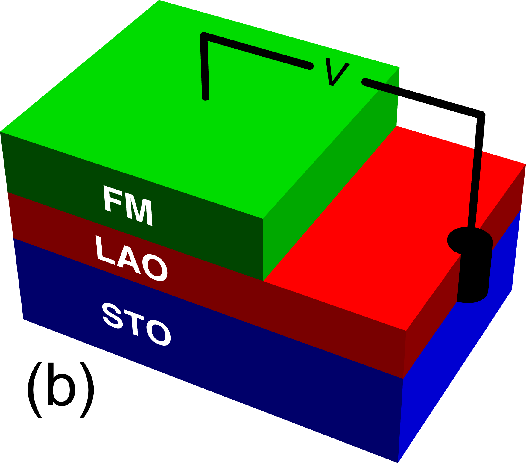
Our MTJ structure is peculiar in that nanoscale QWs with both strong SOC and magnetic ordering are rare. However, an important motivation is the recent experiment Ngo et al. (2014) on the transition metal oxide interface between LaAlO3 (LAO) and SrTiO3 (STO) [see Fig. 1 (b)], where the measured TMR is strongly anisotropic and switches sign as the magnetization direction varies in the interface plane. Since the LAO/STO interface was demonstrated a decade ago Ohtomo and Hwang (2004) to be metallic even though both LAO and STO are typical band insulators, it has attracted ever growing interest by exhibiting superconductivity Reyren et al. (2007), ferromagnetism Brinkman et al. (2007) and even coexistence of both effects Li et al. (2011); Bert et al. (2011). Despite a number of experimental studies of the system, the origins of magnetic ordering and superconductivity remain controversial Michaeli et al. (2012); Chen and Balents (2013) and further studies are imperative. The sign-switching anisotropic TMR Ngo et al. (2014) adds a fresh intriguing question concerning the magnetic properties of the LAO/STO interface. Our results below suggest one possible explanation for it in terms of our MTJ model mentioned above.
Refer to caption
Refer to caption
Refer to caption
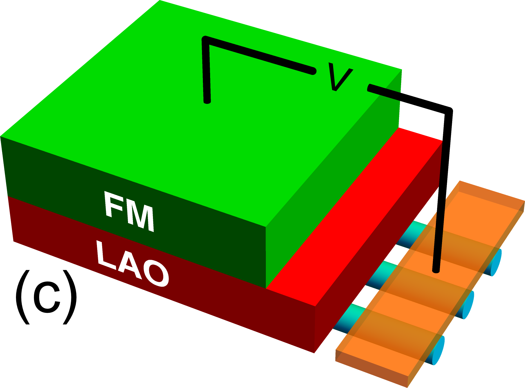
Figure 1: (color online) (a) A double-barrier MTJ of the FM/I/QW(FM+SO)/I/FM structure. (b) A setup to measure the TMR between the top FM and the LAO/STO interface. (c) A simplified model of (b).

Indeed, a recent experiment Kalisky et al. (2013) suggests that the electric conduction in the LAO/STO interface [Fig. 1 (b)] occurs mainly along the narrow paths associated with the twin boundaries in the STO crystal. At the lowest approximation, one can ignore the direct coupling between the narrow conducting paths, which are regarded as QWs; see Fig. 1 (c). As the resistance occurs dominantly at the tunnel junction between the top FM and the QW, one can ignore the resistance along the QWs and the MTJ structures in Fig. 1 (a) and (c) are essentially the same.

Model.

The MTJ is described by the Hamiltonian

H=px2+pz22m+U(z)α(z)pxσy𝚫(z)𝝈,𝐻superscriptsubscript𝑝𝑥2superscriptsubscript𝑝𝑧22𝑚𝑈𝑧𝛼𝑧Planck-constant-over-2-pisubscript𝑝𝑥subscript𝜎𝑦𝚫𝑧𝝈H=\frac{p_{x}^{2}+p_{z}^{2}}{2m}+U(z)-\frac{\alpha(z)}{\hbar}p_{x}\sigma_{y}-\bm{\Delta}(z)\cdot\bf\bm{\sigma}\;, (1)

where σxsubscript𝜎𝑥\sigma_{x}, σysubscript𝜎𝑦\sigma_{y}, and σzsubscript𝜎𝑧\sigma_{z} are the Pauli matrices. We have chosen the x𝑥x-axis along the QW axis and the z𝑧z axis perpendicular to the junction interface [Fig. 1 (a)]. The direction of the effective field (“Rashba field”) due to the Rashba SOC is along the y𝑦y axis. The Rashba SOC is present only on the QW (0<z<d0𝑧𝑑0<z<d):

α(z)={α0(0<z<d)0(otherwise)𝛼𝑧casessubscript𝛼00𝑧𝑑0(otherwise)\alpha(z)=\begin{cases}\alpha_{0}&(0<z<d)\\ 0&\text{(otherwise)}\end{cases} (2)

where d1nmsimilar-to𝑑1nmd\sim 1\operatorname{nm} represents the diameter of the QW or the thickness of the LAO/STO interface. The Zeeman field 𝚫(z)𝚫𝑧\bm{\Delta}(z) is due to the ferromagnetism on the top electrode and the QW and is modeled as a vector in the xy𝑥𝑦xy plane

𝚫(z)={Δ1(sinϕ,cosϕ,0)(z>d),Δ2(sinϕ,cosϕ,0)(0<z<d),0(z<0),𝚫𝑧casessubscriptΔ1italic-ϕitalic-ϕ0𝑧𝑑subscriptΔ2italic-ϕitalic-ϕ00𝑧𝑑0𝑧0\bm{\Delta}(z)=\begin{cases}\Delta_{1}(-\sin\phi,\cos\phi,0)&(z>d)\;,\\ \Delta_{2}(-\sin\phi,\cos\phi,0)&(0<z<d)\;,\\ 0&(z<0),\end{cases} (3)

where the angle ϕitalic-ϕ\phi (0<ϕ<π0italic-ϕ𝜋0<\phi<\pi) is measured from the y𝑦y-axis (Rashba field direction). We assume that Δ1>0subscriptΔ10\Delta_{1}>0 and that Δ2>0subscriptΔ20\Delta_{2}>0 and Δ2<0subscriptΔ20\Delta_{2}<0 for the parallel (P) and anti-parallel (AP) configuration of the magnetic polarization directions, respectively. The chemical potentials (carrier densities) in different regions are described by potential steps and the thin insulating barriers by δ𝛿\delta-potentials, giving the potential profile U(z)𝑈𝑧U(z) of the form

U(z)=U1θ(zd)+U2[Θ(zd)Θ(z)]+abUbδ(zd)+abUbδ(z).𝑈𝑧subscript𝑈1𝜃𝑧𝑑subscript𝑈2delimited-[]Θ𝑧𝑑Θ𝑧subscript𝑎𝑏subscript𝑈𝑏𝛿𝑧𝑑superscriptsubscript𝑎𝑏superscriptsubscript𝑈𝑏𝛿𝑧U(z)=U_{1}\theta(z-d)+U_{2}[\Theta(z-d)-\Theta(z)]\\ {}+a_{b}U_{b}\delta(z-d)+a_{b}^{\prime}U_{b}^{\prime}\delta(z)\,. (4)

Ubsubscript𝑈𝑏U_{b} is responsible for the insulating layer of LAO, absubscript𝑎𝑏a_{b} is the effective width of the barrier (ab15nmsimilar-tosubscript𝑎𝑏15nma_{b}\sim 1\text{--}5\operatorname{nm}), Ubsuperscriptsubscript𝑈𝑏U_{b}^{\prime} is responsible for the junction between the QW and the normal electrode and absuperscriptsubscript𝑎𝑏a_{b}^{\prime} is its effective length scale. For a typical LAO/STO interface Michaeli et al. (2012); Pentcheva and Pickett (2009, 2007, 2008), the Fermi energy EF40meVsimilar-tosubscript𝐸𝐹40meVE_{F}\sim 40\operatorname{meV}, α0vF0/8similar-tosubscript𝛼0Planck-constant-over-2-pisuperscriptsubscript𝑣𝐹08\alpha_{0}\sim\hbar{v_{F}^{0}}/8 with vF02EF/msuperscriptsubscript𝑣𝐹02subscript𝐸𝐹𝑚v_{F}^{0}\equiv\sqrt{2E_{F}/m}, Δ2EF/16similar-tosubscriptΔ2subscript𝐸𝐹16\Delta_{2}\sim E_{F}/16, and d1nmsimilar-to𝑑1nmd\sim 1\operatorname{nm}.

The momentum in the x𝑥x-direction is preserved over a tunneling process end (b). We thus seek a wave function of the form Ψ(x,z)=eiqxψ(z)Ψ𝑥𝑧superscript𝑒𝑖𝑞𝑥𝜓𝑧\Psi(x,z)=e^{iqx}\psi(z), where ψ(z)𝜓𝑧\psi(z) satisfies the 1D Schrödinger equation Hzψ(z)=(E2q2/2m)ψ(z)subscript𝐻𝑧𝜓𝑧𝐸superscriptPlanck-constant-over-2-pi2superscript𝑞22𝑚𝜓𝑧H_{z}\psi(z)=\left(E-{\hbar^{2}q^{2}}/{2m}\right)\psi(z). The 1D effective Hamiltonian Hzsubscript𝐻𝑧H_{z} is given by

Hz=[1001](22md2dz2+U1)Δ1[1001]subscript𝐻𝑧matrix1001superscriptPlanck-constant-over-2-pi22𝑚superscript𝑑2𝑑superscript𝑧2subscript𝑈1subscriptΔ1matrix1001H_{z}=\begin{bmatrix}1&0\\ 0&1\end{bmatrix}\left(-\frac{\hbar^{2}}{2m}\frac{d^{2}}{dz^{2}}+U_{1}\right)-\Delta_{1}\begin{bmatrix}1&0\\ 0&-1\end{bmatrix} (5)

in the region z>d𝑧𝑑z>d, by

Hz=[1001](22md2dz2+U2)[α0qcosϕ+Δ2iα0qsinϕiα0qsinϕ(α0qcosϕ+Δ2)]subscript𝐻𝑧matrix1001superscriptPlanck-constant-over-2-pi22𝑚superscript𝑑2𝑑superscript𝑧2subscript𝑈2matrixsubscript𝛼0𝑞italic-ϕsubscriptΔ2𝑖subscript𝛼0𝑞italic-ϕ𝑖subscript𝛼0𝑞italic-ϕsubscript𝛼0𝑞italic-ϕsubscriptΔ2H_{z}=\begin{bmatrix}1&0\\ 0&1\end{bmatrix}\left(-\frac{\hbar^{2}}{2m}\frac{d^{2}}{dz^{2}}+U_{2}\right)\\ {}-\begin{bmatrix}\alpha_{0}q\cos\phi+\Delta_{2}&-i\alpha_{0}q\sin\phi\\ i\alpha_{0}q\sin\phi&-(\alpha_{0}q\cos\phi+\Delta_{2})\end{bmatrix} (6)

in the region 0<z<d0𝑧𝑑0<z<d, and by

Hz=[1001](22md2dz2)subscript𝐻𝑧matrix1001superscriptPlanck-constant-over-2-pi22𝑚superscript𝑑2𝑑superscript𝑧2H_{z}=\begin{bmatrix}1&0\\ 0&1\end{bmatrix}\left(-\frac{\hbar^{2}}{2m}\frac{d^{2}}{dz^{2}}\right) (7)

in the region z<0𝑧0z<0. Here the spin part of Hzsubscript𝐻𝑧H_{z} has been represented in the eigenbasis {|χ,|χ}delimited-|⟩subscript𝜒delimited-|⟩subscript𝜒\{\mathinner{\lvert{\textstyle\chi_{\uparrow}}\rangle},\mathinner{\lvert{\textstyle\chi_{\downarrow}}\rangle}\} of σycosϕσxsinϕsubscript𝜎𝑦italic-ϕsubscript𝜎𝑥italic-ϕ\sigma_{y}\cos\phi-\sigma_{x}\sin\phi corresponding to the Zeeman field of the top FM (region z>d𝑧𝑑z>d). In the region z>d𝑧𝑑z>d, the plane waves of the form

|χ/eik/z,|χ/eik/zdelimited-|⟩subscript𝜒absentsuperscript𝑒𝑖subscript𝑘absent𝑧delimited-|⟩subscript𝜒absentsuperscript𝑒𝑖subscript𝑘absent𝑧\mathinner{\lvert{\textstyle\chi_{\uparrow/\downarrow}}\rangle}e^{ik_{\uparrow/\downarrow}z}\,,\quad\mathinner{\lvert{\textstyle\chi_{\uparrow/\downarrow}}\rangle}e^{-ik_{\uparrow/\downarrow}z} (8)

with k/2m(EU1±Δ1)/2q2subscript𝑘absent2𝑚plus-or-minus𝐸subscript𝑈1subscriptΔ1superscriptPlanck-constant-over-2-pi2superscript𝑞2k_{\uparrow/\downarrow}\equiv\sqrt{2m(E-U_{1}\pm\Delta_{1})/\hbar^{2}-q^{2}} compose the wave function ψ(z)𝜓𝑧\psi(z). In the region 0<z<d0𝑧𝑑0<z<d, ψ(z)𝜓𝑧\psi(z) is a linear combination of the plane waves of the form

|χ±eik±z,|χ±eik±zdelimited-|⟩subscript𝜒plus-or-minussuperscript𝑒𝑖subscript𝑘plus-or-minus𝑧delimited-|⟩subscript𝜒plus-or-minussuperscript𝑒𝑖subscript𝑘plus-or-minus𝑧\mathinner{\lvert{\textstyle\chi_{\pm}}\rangle}e^{ik_{\pm}z}\,,\quad\mathinner{\lvert{\textstyle\chi_{\pm}}\rangle}e^{-ik_{\pm}z} (9)

where k±2m(EU2±Δ2)/2q2subscript𝑘plus-or-minus2𝑚plus-or-minus𝐸subscript𝑈2subscriptΔ2superscriptPlanck-constant-over-2-pi2superscript𝑞2k_{\pm}\equiv\sqrt{2m(E-U_{2}\pm\Delta_{2})/\hbar^{2}-q^{2}} and

|χ+delimited-|⟩subscript𝜒\displaystyle\mathinner{\lvert{\textstyle\chi_{+}}\rangle} =cos(θ/2)|χ+isin(θ/2)|χabsent𝜃2delimited-|⟩subscript𝜒𝑖𝜃2delimited-|⟩subscript𝜒\displaystyle=\cos(\theta/2)\mathinner{\lvert{\textstyle\chi_{\uparrow}}\rangle}+i\sin(\theta/2)\mathinner{\lvert{\textstyle\chi_{\downarrow}}\rangle} (10a)
|χdelimited-|⟩subscript𝜒\displaystyle\mathinner{\lvert{\textstyle\chi_{-}}\rangle} =isin(θ/2)|χ+cos(θ/2)|χ.absent𝑖𝜃2delimited-|⟩subscript𝜒𝜃2delimited-|⟩subscript𝜒\displaystyle=i\sin(\theta/2)\mathinner{\lvert{\textstyle\chi_{\uparrow}}\rangle}+\cos(\theta/2)\mathinner{\lvert{\textstyle\chi_{\downarrow}}\rangle}. (10b)

Here the angle θ𝜃\theta (0<θ<π0𝜃𝜋0<\theta<\pi) switches between θPsubscript𝜃P\theta_{\mathrm{P}} and θAPsubscript𝜃AP\theta_{\mathrm{AP}} upon the P (θ=θP𝜃subscript𝜃P\theta=\theta_{\mathrm{P}}) and AP (θ=θAP𝜃subscript𝜃AP\theta=\theta_{\mathrm{AP}}) configuration, which are defined by

tanθP/AP=α0qsinϕα0qcosϕ±Δ2.subscript𝜃PAPsubscript𝛼0𝑞italic-ϕplus-or-minussubscript𝛼0𝑞italic-ϕsubscriptΔ2\tan\theta_{\mathrm{P/AP}}=\frac{\alpha_{0}q\sin\phi}{\alpha_{0}q\cos\phi\pm\Delta_{2}}\,. (11)

Imposing proper matching conditions over δ𝛿\delta-potentials at z=0𝑧0z=0 and d𝑑d, we determine (both with numerically exact method and with analytically approximate method) the scattering wave function ψ(z)𝜓𝑧\psi(z) and calculate the TMR ratio, TMR1RP/RAP,TMR1subscript𝑅Psubscript𝑅AP\text{TMR}\equiv 1-{R_{\mathrm{P}}}/{R_{\mathrm{AP}}}, where RP/APsubscript𝑅PAPR_{\mathrm{P/AP}} is the resistance for the P/AP polarization.

Exact Results.

Figure 2 shows the numerically exact results of the TMR as a function of U2subscript𝑈2U_{2} and ϕitalic-ϕ\phi for a typical set of parameters consistent with the LAO/STO interface Michaeli et al. (2012); Pentcheva and Pickett (2009, 2007, 2008). The numerical method involves the integration of the transmission probabilities over the angle of the incident wave. The algorithm has been devised in such a way to ensure a sufficient precision for the angular integrals. The details of the numerical method are described in a previous work by one of the authors Gelabert and Serra (2011).

Refer to caption
Figure 2: (color online) (a) Numerical results of the TMR as a function of U2subscript𝑈2U_{2} and ϕitalic-ϕ\phi for d=4.5/kF0𝑑4.5superscriptsubscript𝑘𝐹0d=4.5/k_{F}^{0} (kF02mEF/2superscriptsubscript𝑘𝐹02𝑚subscript𝐸𝐹superscriptPlanck-constant-over-2-pi2k_{F}^{0}\equiv\sqrt{2mE_{F}/\hbar^{2}}), α0=vF0/82subscript𝛼0Planck-constant-over-2-pisuperscriptsubscript𝑣𝐹082\alpha_{0}=\hbar{v_{F}^{0}}/8\sqrt{2}, Δ1=EF/8subscriptΔ1subscript𝐸𝐹8\Delta_{1}=E_{F}/8, Δ2=EF/16subscriptΔ2subscript𝐸𝐹16\Delta_{2}=E_{F}/16 and U1=EF/4subscript𝑈1subscript𝐸𝐹4U_{1}=E_{F}/4. (b) Cuts along ϕ=0italic-ϕ0\phi=0 (black dots, y𝑦y polarization) and ϕ=π/2italic-ϕ𝜋2\phi=\pi/2 (red-gray dots, xz𝑥𝑧x-z polarization). (c) Cuts along ϕitalic-ϕ\phi for the indicated fixed values of U2=0.17EFsubscript𝑈20.17subscript𝐸𝐹U_{2}=-0.17E_{F} and U2=0.40EFsubscript𝑈20.40subscript𝐸𝐹U_{2}=-0.40E_{F}.

It is shown in Fig. 2 that the TMR can be negative as much as 10%percent10-10\%. Further, it reveals two additional interesting features: First, the TMR depends rather strongly on U2subscript𝑈2U_{2} [Fig. 2 (b)]. Experimentally, U2subscript𝑈2U_{2} corresponds to the backgate voltage and controls the carrier density on the QW (or the LAO/STO interface). In the recent experiment Ngo et al. (2014), on the other hand, the TMR did not depend much on the gate voltage. However, the actual gate capacitance was not known and it is not clear how large is the actual energy range covered by the gate voltage variation. The gate voltage dependence needs to be tested further. Moreover, in real samples (even if there are twin boundaries) the electric conduction is not completely confined to the narrow paths.

A second remarkable thing of Fig. 2 is the change of the ϕitalic-ϕ\phi dependence from a cos(ϕ/2)italic-ϕ2\cos(\phi/2) to a cos(ϕ/2)italic-ϕ2-\cos(\phi/2) behavior by tuning the value of U2subscript𝑈2U_{2} [Fig. 2 (c)]. This is seen as a reversed change of sign of the TMR when going from ϕ=0italic-ϕ0\phi=0 to ϕ=π/2italic-ϕ𝜋2\phi=\pi/2; from positive to negative for U2=0.4EFsubscript𝑈20.4subscript𝐸𝐹U_{2}=-0.4E_{F}, and reversed for U2=0.17EFsubscript𝑈20.17subscript𝐸𝐹U_{2}=-0.17E_{F}.

As we discuss below, both features of the exact results can be understood qualitatively by means of an analytical (but approximate) method.

Qualitative Features of Single-Barrier Tunneling.

We first examine the transmission over the first barrier at z=d𝑧𝑑z=d. Before going further, recall the transmission problem of a spinless particle with energy E𝐸E over a potential barrier Ubsubscript𝑈𝑏U_{b}, U(z)=U1Θ(z)+U2Θ(z)+abUbδ(z)𝑈𝑧subscript𝑈1Θ𝑧subscript𝑈2Θ𝑧subscript𝑎𝑏subscript𝑈𝑏𝛿𝑧U(z)=U_{1}\Theta(-z)+U_{2}\Theta(z)+a_{b}U_{b}\delta(z). The transmission amplitude t𝑡t is given by

t(qb;k1,k2)=k1k2(k1+k2)/2+iqb,𝑡subscript𝑞𝑏subscript𝑘1subscript𝑘2subscript𝑘1subscript𝑘2subscript𝑘1subscript𝑘22𝑖subscript𝑞𝑏t(q_{b};k_{1},k_{2})=\frac{\sqrt{k_{1}k_{2}}}{(k_{1}+k_{2})/2+iq_{b}}\;, (12)

where kj2m(EUj)/2subscript𝑘𝑗2𝑚𝐸subscript𝑈𝑗superscriptPlanck-constant-over-2-pi2k_{j}\equiv\sqrt{{2m(E-U_{j})}/{\hbar^{2}}} and qbmabUb/2.subscript𝑞𝑏𝑚subscript𝑎𝑏subscript𝑈𝑏superscriptPlanck-constant-over-2-pi2q_{b}\equiv{ma_{b}U_{b}}/{\hbar^{2}}. When the barrier is sufficiently high (UbEmuch-greater-thansubscript𝑈𝑏𝐸U_{b}\gg E), it can be approximated as

t(qb;k1,k2)k1k2iqb.𝑡subscript𝑞𝑏subscript𝑘1subscript𝑘2subscript𝑘1subscript𝑘2𝑖subscript𝑞𝑏t(q_{b};k_{1},k_{2})\approx\frac{\sqrt{k_{1}k_{2}}}{iq_{b}}\;. (13)

Consider now a scattering state ψ±(z)subscript𝜓plus-or-minus𝑧\psi_{\pm}(z) of the form

ψ±(z)={s=,(As|χseiksz+Bs|χseiksz)(z>d)C±|χ±eik±z(z<d)subscript𝜓plus-or-minus𝑧casessubscript𝑠subscript𝐴𝑠delimited-|⟩subscript𝜒𝑠superscript𝑒𝑖subscript𝑘𝑠𝑧subscript𝐵𝑠delimited-|⟩subscript𝜒𝑠superscript𝑒𝑖subscript𝑘𝑠𝑧𝑧𝑑subscript𝐶plus-or-minusdelimited-|⟩subscript𝜒plus-or-minussuperscript𝑒𝑖subscript𝑘plus-or-minus𝑧𝑧𝑑\psi_{\pm}(z)=\begin{cases}\displaystyle\sum_{s=\uparrow,\downarrow}\left(A_{s}\mathinner{\lvert{\textstyle\chi_{s}}\rangle}e^{-ik_{s}z}+B_{s}\mathinner{\lvert{\textstyle\chi_{s}}\rangle}e^{ik_{s}z}\right)&(z>d)\\[14.22636pt] C_{\pm}\mathinner{\lvert{\textstyle\chi_{\pm}}\rangle}e^{-ik_{\pm}z}&(z<d)\end{cases} (14)

Here we have imposed a boundary condition such that in the region z<d𝑧𝑑z<d there is only one propagating spin channel |χμdelimited-|⟩subscript𝜒𝜇\mathinner{\lvert{\textstyle\chi_{\mu}}\rangle} of fixed μ=±𝜇plus-or-minus\mu=\pm. On the one hand, the coefficients Assubscript𝐴𝑠A_{s} and Cμsubscript𝐶𝜇C_{\mu} are related through the transmission coefficients tμssubscript𝑡𝜇𝑠t_{\mu s} by Cμ=stμsAssubscript𝐶𝜇subscript𝑠subscript𝑡𝜇𝑠subscript𝐴𝑠C_{\mu}=\sum_{s}t_{\mu s}A_{s}. On the other hand, the matching conditions over the δ𝛿\delta-barrier are equivalent to those on the wave function of the form

ημs(z)={Aseiksz+Bseiksz(z>d)Cμχs|χμeikμz(z<d)subscript𝜂𝜇𝑠𝑧casessubscript𝐴𝑠superscript𝑒𝑖subscript𝑘𝑠𝑧subscript𝐵𝑠superscript𝑒𝑖subscript𝑘𝑠𝑧𝑧𝑑subscript𝐶𝜇inner-productsubscript𝜒𝑠subscript𝜒𝜇superscript𝑒𝑖subscript𝑘𝜇𝑧𝑧𝑑\displaystyle\eta_{\mu s}(z)=\begin{cases}A_{s}e^{-ik_{s}z}+B_{s}e^{ik_{s}z}&(z>d)\\ C_{\mu}\mathinner{\langle{\textstyle\chi_{s}|\chi_{\mu}}\rangle}e^{-ik_{\mu}z}&(z<d)\end{cases} (15)

imposed separately for each component s=,𝑠s=\uparrow,\downarrow. This implies by Eq. (12) that Cμχs|χμ=Ast(qb;kμ,ks)subscript𝐶𝜇inner-productsubscript𝜒𝑠subscript𝜒𝜇subscript𝐴𝑠𝑡subscript𝑞𝑏subscript𝑘𝜇subscript𝑘𝑠C_{\mu}\mathinner{\langle{\textstyle\chi_{s}|\chi_{\mu}}\rangle}=A_{s}t(q_{b};k_{\mu},k_{s}). Combining these two relations leads to

[1001]=[t+t+tt][χ|χ+t(qb;k+,k)χ|χt(qb;k,k)χ|χ+t(qb;k+,k)χ|χt(qb;k,k)]matrix1001matrixsubscript𝑡absentsubscript𝑡absentsubscript𝑡absentsubscript𝑡absentmatrixinner-productsubscript𝜒subscript𝜒𝑡subscript𝑞𝑏subscript𝑘subscript𝑘inner-productsubscript𝜒subscript𝜒𝑡subscript𝑞𝑏subscript𝑘subscript𝑘inner-productsubscript𝜒subscript𝜒𝑡subscript𝑞𝑏subscript𝑘subscript𝑘inner-productsubscript𝜒subscript𝜒𝑡subscript𝑞𝑏subscript𝑘subscript𝑘\begin{bmatrix}1&0\\ 0&1\end{bmatrix}=\begin{bmatrix}t_{+\uparrow}&t_{+\downarrow}\\ t_{-\uparrow}&t_{-\downarrow}\end{bmatrix}\begin{bmatrix}\frac{\mathinner{\langle{\textstyle\chi_{\uparrow}|\chi_{+}}\rangle}}{t(q_{b};k_{+},k_{\uparrow})}&\frac{\mathinner{\langle{\textstyle\chi_{\uparrow}|\chi_{-}}\rangle}}{t(q_{b};k_{-},k_{\uparrow})}\\ \frac{\mathinner{\langle{\textstyle\chi_{\downarrow}|\chi_{+}}\rangle}}{t(q_{b};k_{+},k_{\downarrow})}&\frac{\mathinner{\langle{\textstyle\chi_{\downarrow}|\chi_{-}}\rangle}}{t(q_{b};k_{-},k_{\downarrow})}\end{bmatrix} (16)

Using the approximation (13), the matrix on the right hand side of (16) is factorized as

[t+t+tt]i[k+/qb00k/qb]×[χ+|χχ+|χχ|χχ|χ][k/qb00k/qb]matrixsubscript𝑡absentsubscript𝑡absentsubscript𝑡absentsubscript𝑡absent𝑖matrixsubscript𝑘subscript𝑞𝑏00subscript𝑘subscript𝑞𝑏matrixinner-productsubscript𝜒subscript𝜒inner-productsubscript𝜒subscript𝜒inner-productsubscript𝜒subscript𝜒inner-productsubscript𝜒subscript𝜒matrixsubscript𝑘subscript𝑞𝑏00subscript𝑘subscript𝑞𝑏\begin{bmatrix}t_{+\uparrow}&t_{+\downarrow}\\ t_{-\uparrow}&t_{-\downarrow}\end{bmatrix}\approx i\begin{bmatrix}\sqrt{k_{+}/q_{b}}&0\\ 0&\sqrt{k_{-}/q_{b}}\end{bmatrix}\\ {}\times\begin{bmatrix}\mathinner{\langle{\textstyle\chi_{+}|\chi_{\uparrow}}\rangle}&\mathinner{\langle{\textstyle\chi_{+}|\chi_{\downarrow}}\rangle}\\ \mathinner{\langle{\textstyle\chi_{-}|\chi_{\uparrow}}\rangle}&\mathinner{\langle{\textstyle\chi_{-}|\chi_{\downarrow}}\rangle}\end{bmatrix}\begin{bmatrix}\sqrt{k_{\uparrow}/q_{b}}&0\\ 0&\sqrt{k_{\downarrow}/q_{b}}\end{bmatrix} (17)

The transmission probabilities Tμ(q)s|tμs|2subscript𝑇𝜇𝑞subscript𝑠superscriptsubscript𝑡𝜇𝑠2T_{\mu}(q)\equiv\sum_{s}\left|t_{\mu s}\right|^{2} for the channels μ=±𝜇plus-or-minus\mu=\pm are given by

T±(q)k+k2qb[k±qb±4mΔ12(k+k)2cosθ]subscript𝑇plus-or-minus𝑞subscript𝑘subscript𝑘2subscript𝑞𝑏delimited-[]plus-or-minussubscript𝑘plus-or-minussubscript𝑞𝑏4𝑚subscriptΔ1superscriptPlanck-constant-over-2-pi2superscriptsubscript𝑘subscript𝑘2𝜃T_{\pm}(q)\approx\frac{k_{\uparrow}+k_{\downarrow}}{2q_{b}}\left[\frac{k_{\pm}}{q_{b}}\pm\frac{4m\Delta_{1}}{\hbar^{2}(k_{\uparrow}+k_{\downarrow})^{2}}\cos\theta\right] (18)

where the q𝑞q-dependence of k/subscript𝑘absentk_{\uparrow/\downarrow}, k±subscript𝑘plus-or-minusk_{\pm} and θ𝜃\theta is implied. The expressions (18) for the transmission probabilities between a ferromagnet and another ferromagnet with strong Rashba SOC is one of our main results.

Qualitative Features of the Double-Barrier Structure.

Now we investigate the full double-barrier structure for all possible values of q𝑞q. For high tunnel barriers, the wave number k±subscript𝑘plus-or-minusk_{\pm} in the central region (0<z<d0𝑧𝑑0<z<d) is quantized to knnπ/dsubscript𝑘𝑛𝑛𝜋𝑑k_{n}\approx n\pi/d (n=1,2,𝑛12n=1,2,\cdots) and the wave function takes the form Ψ(x,z)=|χ±(qn,±ν)sin(knz)eiqn,±νx.Ψ𝑥𝑧delimited-|⟩subscript𝜒plus-or-minussuperscriptsubscript𝑞𝑛plus-or-minus𝜈subscript𝑘𝑛𝑧superscript𝑒𝑖superscriptsubscript𝑞𝑛plus-or-minus𝜈𝑥\Psi(x,z)=\mathinner{\lvert{\textstyle\chi_{\pm}(q_{n,\pm}^{\nu})}\rangle}\sin(k_{n}z)e^{iq_{n,\pm}^{\nu}x}. For each knsubscript𝑘𝑛k_{n} and a given energy E𝐸E, the allowed values qn,±νsuperscriptsubscript𝑞𝑛plus-or-minus𝜈q_{n,\pm}^{\nu} (ν=𝜈less-than-or-greater-than\nu=\lessgtr) is determined by the dispersion relation

E=22m[kn2+(q±ν)2]+U2(α0qn,±ν)2+2(α0qn,±ν)Δ2cosϕ+Δ22.𝐸minus-or-plussuperscriptPlanck-constant-over-2-pi22𝑚delimited-[]superscriptsubscript𝑘𝑛2superscriptsuperscriptsubscript𝑞plus-or-minus𝜈2subscript𝑈2superscriptsubscript𝛼0superscriptsubscript𝑞𝑛plus-or-minus𝜈22subscript𝛼0superscriptsubscript𝑞𝑛plus-or-minus𝜈subscriptΔ2italic-ϕsuperscriptsubscriptΔ22E=\frac{\hbar^{2}}{2m}\left[k_{n}^{2}+(q_{\pm}^{\nu})^{2}\right]+U_{2}\\ {}\mp\sqrt{\left(\alpha_{0}q_{n,\pm}^{\nu}\right)^{2}+2\left(\alpha_{0}q_{n,\pm}^{\nu}\right)\Delta_{2}\cos\phi+\Delta_{2}^{2}}\,. (19)

Due to narrow confinement (d1nmsimilar-to𝑑1nmd\sim 1\operatorname{nm}) and strong SOC (αqE/8similar-to-or-equals𝛼𝑞𝐸8\alpha{q}\simeq E/8), typically only one kn±superscriptsubscript𝑘𝑛plus-or-minusk_{n}^{\pm} is allowed for each ±plus-or-minus\pm. Hereafter we thus drop the subscript n𝑛n: kkn𝑘subscript𝑘𝑛k\equiv k_{n}, q±νqn,±νsuperscriptsubscript𝑞plus-or-minus𝜈superscriptsubscript𝑞𝑛plus-or-minus𝜈q_{\pm}^{\nu}\equiv q_{n,\pm}^{\nu} and |χ±ν|χ±(qn,±ν)delimited-|⟩superscriptsubscript𝜒plus-or-minus𝜈delimited-|⟩subscript𝜒plus-or-minussuperscriptsubscript𝑞𝑛plus-or-minus𝜈\mathinner{\lvert{\textstyle\chi_{\pm}^{\nu}}\rangle}\equiv\mathinner{\lvert{\textstyle\chi_{\pm}(q_{n,\pm}^{\nu})}\rangle}. The total transmission probability is given by T=μ=±[Tμ(qμ>)+Tμ(qμ<)].𝑇subscript𝜇plus-or-minusdelimited-[]subscript𝑇𝜇superscriptsubscript𝑞𝜇subscript𝑇𝜇superscriptsubscript𝑞𝜇T=\sum_{\mu=\pm}\left[T_{\mu}(q_{\mu}^{>})+T_{\mu}(q_{\mu}^{<})\right].

Refer to caption
Figure 3: (color online) The spin-split Fermi circles in the FM electrode (top) and the dispersion relation in the QW (bottom) for ϕ=π/2italic-ϕ𝜋2\phi=\pi/2 [(a) and (b)] and for ϕ=0italic-ϕ0\phi=0 [(c) and (d)]. The thin horizontal lines indicate the Fermi levels relative to the band bottoms and the short arrows depict the spin quantization directions. In (a) and (c) all transverse modes at the Fermi level on the QW contribute to the transport whereas the two outer modes in (b) and the q+>superscriptsubscript𝑞q_{+}^{>}-mode in (d) do not.

For ϕ=π/2italic-ϕ𝜋2\phi=\pi/2, the Zeeman field is perpendicular to the Rashba field and the dispersion relation is particularly simple. Especially, one has q±>=q±<q±superscriptsubscript𝑞plus-or-minussuperscriptsubscript𝑞plus-or-minussubscript𝑞plus-or-minusq_{\pm}^{>}=-q_{\pm}^{<}\equiv q_{\pm}, q+>qsubscript𝑞subscript𝑞q_{+}>q_{-}, cosθP(q±)>0subscript𝜃Psubscript𝑞plus-or-minus0\cos\theta_{\mathrm{P}}(q_{\pm})>0, cosθAP(q±)<0subscript𝜃APsubscript𝑞plus-or-minus0\cos\theta_{\mathrm{AP}}(q_{\pm})<0, and T=2[T+(q+)+T(q)]𝑇2delimited-[]subscript𝑇subscript𝑞subscript𝑇subscript𝑞T=2\left[T_{+}(q_{+})+T_{-}(q_{-})\right]. When both q±subscript𝑞plus-or-minusq_{\pm} contribute to the transport [Fig. 3 (a)],

TMRcosθP(q+)cosθAP(q+)k(q+)+k(q+)cosθP(q)cosθAP(q)k(q)+k(q)proportional-toTMRsubscript𝜃Psubscript𝑞subscript𝜃APsubscript𝑞subscript𝑘subscript𝑞subscript𝑘subscript𝑞subscript𝜃Psubscript𝑞subscript𝜃APsubscript𝑞subscript𝑘subscript𝑞subscript𝑘subscript𝑞\text{TMR}\propto\frac{\cos\theta_{\mathrm{P}}(q_{+})-\cos\theta_{\mathrm{AP}}(q_{+})}{k_{\uparrow}(q_{+})+k_{\downarrow}(q_{+})}\\ {}-\frac{\cos\theta_{\mathrm{P}}(q_{-})-\cos\theta_{\mathrm{AP}}(q_{-})}{k_{\uparrow}(q_{-})+k_{\downarrow}(q_{-})} (20)

The q+subscript𝑞q_{+} (qsubscript𝑞q_{-}) channel contributes a positive (negative) TMR. As q+>qsubscript𝑞subscript𝑞q_{+}>q_{-}, k(q+)+k(q+)<k(q)+k(q)subscript𝑘subscript𝑞subscript𝑘subscript𝑞subscript𝑘subscript𝑞subscript𝑘subscript𝑞k_{\uparrow}(q_{+})+k_{\downarrow}(q_{+})<k_{\uparrow}(q_{-})+k_{\downarrow}(q_{-}) and the positive contribution from q+subscript𝑞q_{+}-channel dominates. When q+subscript𝑞q_{+}-channel is not allowed [Fig. 3 (b)], T(q)subscript𝑇subscript𝑞T_{-}(q_{-}) from the qsubscript𝑞q_{-} channel is the sole contribution and the TMR becomes negative.

For ϕ=0italic-ϕ0\phi=0 (ϕ=πitalic-ϕ𝜋\phi=\pi), θP(q±)=θAP(q±)=0subscript𝜃Psuperscriptsubscript𝑞plus-or-minusgreater-than-or-less-thansubscript𝜃APsuperscriptsubscript𝑞plus-or-minusgreater-than-or-less-than0\theta_{\mathrm{P}}(q_{\pm}^{\gtrless})=\theta_{\mathrm{AP}}(q_{\pm}^{\gtrless})=0 and the total transmission reads as [Eq. (18) with k±=ksubscript𝑘plus-or-minus𝑘k_{\pm}=k]

T=kqb2[k(q>)+k(q<)+k(q+<)+k(q+>)].𝑇𝑘superscriptsubscript𝑞𝑏2delimited-[]subscript𝑘superscriptsubscript𝑞subscript𝑘superscriptsubscript𝑞subscript𝑘superscriptsubscript𝑞subscript𝑘superscriptsubscript𝑞T=\frac{k}{q_{b}^{2}}\left[k_{\downarrow}(q_{-}^{>})+k_{\uparrow}(q_{-}^{<})+k_{\downarrow}(q_{+}^{<})+k_{\uparrow}(q_{+}^{>})\right]. (21)

Note that q+>>q+<>q<>q>>0superscriptsubscript𝑞superscriptsubscript𝑞superscriptsubscript𝑞superscriptsubscript𝑞0q_{+}^{>}>-q_{+}^{<}>-q_{-}^{<}>q_{-}^{>}>0 in the P polarization configuration [Fig. 3 (c) and (d)]. The TMR is then given by

TMR[k(q+>)k(q+>)][k(q+<)k(q+<)]+[k(q<)k(q<)][k(q>)k(q>)]proportional-toTMRdelimited-[]subscript𝑘superscriptsubscript𝑞subscript𝑘superscriptsubscript𝑞delimited-[]subscript𝑘superscriptsubscript𝑞subscript𝑘superscriptsubscript𝑞delimited-[]subscript𝑘superscriptsubscript𝑞subscript𝑘superscriptsubscript𝑞delimited-[]subscript𝑘superscriptsubscript𝑞subscript𝑘superscriptsubscript𝑞\text{TMR}\propto[k_{\uparrow}(q_{+}^{>})-k_{\downarrow}(q_{+}^{>})]-[k_{\uparrow}(q_{+}^{<})-k_{\downarrow}(q_{+}^{<})]\\ {}+[k_{\uparrow}(q_{-}^{<})-k_{\downarrow}(q_{-}^{<})]-[k_{\uparrow}(q_{-}^{>})-k_{\downarrow}(q_{-}^{>})] (22)

where the terms have been arranged in decreasing order (all values within square brackets are positive) and all q±superscriptsubscript𝑞plus-or-minusgreater-than-or-less-thanq_{\pm}^{\gtrless} have been defined for the P polarization configuration. As U2subscript𝑈2U_{2} (the chemical potential in the central region) varies, the q+>superscriptsubscript𝑞q_{+}^{>} channel may become disallowed [Fig. 3 (d)]. In such a case, there are more negative contributions to the TMR. As U2subscript𝑈2U_{2} varies further, the q+<superscriptsubscript𝑞q_{+}^{<} channel is also disallowed, and the TMR becomes positive again. As U2subscript𝑈2U_{2} varies even further, the q<superscriptsubscript𝑞q_{-}^{<} channel stops contributing to the transport and the TMR becomes negative once more.

Putting all together, with U2subscript𝑈2U_{2}\to-\infty, TMR is positive both at ϕ=0italic-ϕ0\phi=0 and ϕ=π/2italic-ϕ𝜋2\phi=\pi/2. As U2subscript𝑈2U_{2} moves up, the q+>superscriptsubscript𝑞q_{+}^{>}-mode at ϕ=π/2italic-ϕ𝜋2\phi=\pi/2 gets disallowed first at U20.6EFsubscript𝑈20.6subscript𝐸𝐹U_{2}\approx-0.6E_{F}; the TMR(ϕ=π/2italic-ϕ𝜋2\phi=\pi/2) becomes negative but TMR(0) remains positive. At U20.5EFsubscript𝑈20.5subscript𝐸𝐹U_{2}\approx-0.5E_{F}, the q+>superscriptsubscript𝑞q_{+}^{>} mode at ϕ=0,πitalic-ϕ0𝜋\phi=0,\pi gets disallowed and both TMR(π/2)𝜋2(\pi/2) and TMR(0)0(0) become negative. But quite soon at U20.45EFsubscript𝑈20.45subscript𝐸𝐹U_{2}\approx-0.45E_{F}, the q+<superscriptsubscript𝑞q_{+}^{<} mode gets disallowed and TMR(0) quickly becomes positive again. Therefore, until U20.2EFsubscript𝑈20.2subscript𝐸𝐹U_{2}\approx-0.2E_{F}, where both spin channels get disallowed, TMR(π/2𝜋2\pi/2) and TMR(0) remain negative and positive, respectively. As a function of ϕitalic-ϕ\phi, the TMR is expected to behave like cos(ϕ/2)italic-ϕ2\cos(\phi/2). This is consistent with Fig. 2 (b) and (c) for U20.2EFless-than-or-similar-tosubscript𝑈20.2subscript𝐸𝐹U_{2}\lesssim-0.2E_{F}.

We stress that in these qualitative arguments, evanescent waves have been ignored completely. In particular, for U20.2EFgreater-than-or-equivalent-tosubscript𝑈20.2subscript𝐸𝐹U_{2}\gtrsim-0.2E_{F} (with other parameters fixed as given), both spin channels are evanescent end (c) in the central region (0<z<d0𝑧𝑑0<z<d) and cannot be addressed within the approximate analytical method. Quite interestingly, as we have seen above, the contributions of the evanescent waves are highly nontrivial in this parameter range and give rise to cos(ϕ/2)italic-ϕ2-\cos(\phi/2) behavior.

Conclusion.

We have considered a double-barrier MTJ consisting of a ferromagnetic electrode, a QW with magnetic ordering and strong Rashba spin-orbit coupling, and a normal metal electrode where the junction is formed on the cylindrical shell of the QW. The structure may have a relevance as a simplified model for the magnetic tunnel junction with a LAO/STO transition metal oxide interface including twin boundaries. The latter has been reported to exhibit sign-switching anisotropic TMR. By means of both qualitative analysis and numerically exact calculations, we have shown that our model exhibits a sign-switching anisotropic TMR. The negative TMR occurs as a combined effect of one-dimensionality, magnetic order, and strong SOC in the QW.

Acknowledgments.

This work was supported by the BK21 Plus Project from the Korean Government and by MINECO (Spain) Grant FIS2011-23526.

References

  • Wolf et al. (2001) S. A. Wolf, D. D. Awschalom, R. A. Buhrman, J. M. Daughton, S. von Molnár, M. L. Roukes, A. Y. Chtchelkanova, and D. M. Treger, Science 294, 1488 (2001).
  • Moodera et al. (2010) J. S. Moodera, G.-X. Miao, and T. S. Santos, Physics Today 63, 46 (2010).
  • Miyazaki and Tezuka (1995) T. Miyazaki and N. Tezuka, Journal of Magnetism and Magnetic Materials 139, L231 (1995).
  • Tsymbal et al. (2003) E. Y. Tsymbal, A. Sokolov, I. F. Sabirianov, and B. Doudin, Phys. Rev. Lett. 90, 186602 (2003).
  • Sahoo et al. (2005) S. Sahoo, T. Kontos, J. Furer, C. Hoffmann, M. Gräber, A. Cottet, and C. Schönenberger, Nature Phys. 1, 99 (2005).
  • Cottet et al. (2006) A. Cottet, T. Kontos, S. Sahoo, H. T. Man, M.-S. Choi, W. Belzig, C. Bruder, A. Morpurgo, and C. Schönenberger, Semicond. Sci. Technol. 21, S78 (2006).
  • Cottet and Choi (2006) A. Cottet and M.-S. Choi, Phys. Rev. B 74, 235316 (2006).
  • Yuasa et al. (2002) S. Yuasa, T. Nagahama, and Y. Suzuki, Science 297, 234 (2002).
  • end (a) The transport is thus across (not along) the axis of the QW.
  • Matos-Abiague and Fabian (2009) A. Matos-Abiague and J. Fabian, Phys. Rev. B 79, 155303 (2009).
  • Ngo et al. (2014) T. D. N. Ngo et al., Polarity-tunable magnetic tunnel junctions based on ferromagnetism at oxide heterointerfaces, unpublished (2014).
  • Ohtomo and Hwang (2004) A. Ohtomo and H. Y. Hwang, Nature 427, 423 (2004).
  • Reyren et al. (2007) N. Reyren, S. Thiel, A. D. Caviglia, L. F. Kourkoutis, G. Hammerl, C. Richter, C. W. Schneider, T. Kopp, A.-S. Rüetschi, D. Jaccard, et al., Science 317, 1196 (2007).
  • Brinkman et al. (2007) A. Brinkman, M. Huijben, M. van Zalk, J. Huijben, U. Zeitler, J. C. Maan, W. G. van der Wiel, G. Rijnders, D. H. A. Blank, and H. Hilgenkamp, Nat Mater 6, 493 (2007).
  • Li et al. (2011) L. Li, C. Richter, J. Mannhart, and R. C. Ashoori, Nat Phys 7, 762 (2011).
  • Bert et al. (2011) J. A. Bert, B. Kalisky, C. Bell, M. Kim, Y. Hikita, H. Y. Hwang, and K. A. Moler, Nat Phys 7, 767 (2011).
  • Michaeli et al. (2012) K. Michaeli, A. C. Potter, and P. A. Lee, Phys. Rev. Lett. 108, 117003 (2012).
  • Chen and Balents (2013) G. Chen and L. Balents, Phys. Rev. Lett. 110, 206401 (2013).
  • Kalisky et al. (2013) B. Kalisky, E. M. Spanton, H. Noad, J. R. Kirtley, K. C. Nowack, C. Bell, H. K. Sato, M. Hosoda, Y. Xie, Y. Hikita, et al., Nat Mater 12, 1091 (2013).
  • Pentcheva and Pickett (2009) R. Pentcheva and W. E. Pickett, Phys. Rev. Lett. 102, 107602 (2009).
  • Pentcheva and Pickett (2007) R. Pentcheva and W. E. Pickett, Phys. Rev. Lett. 99, 016802 (2007).
  • Pentcheva and Pickett (2008) R. Pentcheva and W. E. Pickett, Phys. Rev. B 78, 205106 (2008).
  • end (b) Here we assume that the junction (QW) is infinitely wide (long).
  • Gelabert and Serra (2011) M. M. Gelabert and L. Serra, Eur. Phys. J. B 79, 341 (2011).
  • end (c) Even if the energy is positive, evanescent waves appear already for negative U2subscript𝑈2U_{2} because of the strong Rashba SOC in the centeral region (0<z<d0𝑧𝑑0<z<d).