Diffusion-Based Coarse Graining in Hybrid Continuum–Discrete Solvers: Theoretical Formulation and A Priori Tests
Abstract
Coarse graining is an important ingredient in many multi-scale continuum-discrete solvers such as CFD–DEM (computational fluid dynamics–discrete element method) solvers for dense particle-laden flows. Although CFD–DEM solvers have become a mature technique that is widely used in multiphase flow research and industrial flow simulations, a flexible and easy-to-implement coarse graining algorithm that can work with CFD solvers of arbitrary meshes is still lacking. In this work, we proposed a new coarse graining algorithm for continuum–discrete solvers for dense particle-laden flows based on solving a transient diffusion equation. Via theoretical analysis we demonstrated that the proposed method is equivalent to the statistical kernel method with a Gaussian kernel, but the current method is much more straightforward to implement in CFD–DEM solvers. A priori numerical tests were performed to obtain the solid volume fraction fields based on given particle distributions, the results obtained by using the proposed algorithm were compared with those from other coarse graining methods in the literature (e.g., the particle centroid method, the divided particle volume method, and the two-grid formulation). The numerical tests demonstrated that the proposed coarse graining procedure based on solving diffusion equations is theoretically sound, easy to implement and parallelize in general CFD solvers, and has improved mesh-convergence characteristics compared with existing coarse graining methods. The diffusion-based coarse graining method has been implemented into a CFD–DEM solver, the results of which are presented in a separate work (R. Sun and H. Xiao, Diffusion-based coarse graining in hybrid continuum-discrete solvers: Application in CFD-DEM solvers for particle laden flows. International Journal of Multiphase Flow 72, 233–247).
keywords:
CFD–DEM , Coarse Graining , Multi-scale Modeling1 Introduction
1.1 Coarse Graining in Continuum–Discrete Modeling
In computational mechanics for solids and fluids, continuum methods based on partial differential equations, e.g., the Navier-Stokes or elasticity equations, are usually discretized by the finite-difference, finite-volume, or finite-element method and used to investigate macroscopic system responses, e.g., structural deformations or fluid flows (Mitchell and Griffiths, 1980; Versteeg and Malalasekera, 2007; Zienkiewicz and Morice, 1971). On the other hand, discrete methods such as molecular dynamics and direct simulation Monte Carlo methods are used to simulate microscopic properties of systems at length- and time-scales that are much smaller than those studies by using continuum methods (Piekos and Breuer, 1996; Belytschko et al., 2002). Continuum and discrete methods are complementary to each other, not only in terms of the length- and time-scales they cover, but also because they are used for different purposes.
Traditionally, continuum and discrete methods have been developed in separate communities without significant interactions. This is partly a reflection of the scale separation in classical continuum mechanics; that is, the scales of the representative volume element (RVE) are many orders of magnitude larger than those of the individual molecules or atoms therein. As a consequence, the phenomena of interests in the macroscopic scales and those in the microscopic scales are dramatically different. However, the past few decades have seen a surge of interests in the development of methods aiming for bridging the continuum and the microscopic scales. These efforts originate from several communities with a diverse physical settings ranging from fracture mechanics (Belytschko and Xiao, 2003; Xiao and Belytschko, 2004) and complex fluids (Donev et al., 2010) to materials sciences (e.g., Delgado-Buscalioni et al., 2005; Eidel, 2009; Müller, 2013; Rottler, 2013; Curtin, 2013). In spite of these efforts, many theoretical and practical challenges exist in these multi-scale models. A particular difficulty that is common among most continuum–discrete solvers is the coupling between the continuum solver and the discrete solver with guaranteed conservation of relevant quantities. This is due to the fact that the conservation equations on the two scales are formulated for quantities of vastly different natures, and thus the bridging between the microscopic and macroscopic quantities are critical yet extremely difficult to achieve (Xiao and Belytschko, 2004; Delgado-Buscalioni et al., 2005). In this work we highlight the difficulties of coarse graining in the context of continuum–discrete solvers for dense particle-laden multiphase flows. Subsequently, a strategy that is theoretically meritorious and convenient for numerical implementations is proposed. However, since the difficulties associated with coarse graining are common among many other continuum–discrete methods, it is expected that the strategy developed in this work shall be useful for those methods as well.
1.2 Coarse Graining in CFD–DEM Solvers
Dense particle-laden flows are encountered in a wide range of industrial applications and natural processes including fluidized-bed reactors in chemical engineering (Müller et al., 2008, 2009), pneumatic conveyors in the mineral processing industries (Han et al., 2003), and sediment transport processes in riverine and coastal flows (Drake and Calantoni, 2001; Calantoni et al., 2004). A class of continuum–discrete methods have been proposed and developed in the past two decades, where the fluid (the carrier phase) is modeled with a continuum approach in the Eulerian framework, while the particles (the dispersed phase) are tracked individually in the Lagrangian framework accounting for the inter-particle collisions and fluid–particle interactions. Compared with other alternatives such as the two-fluid model and direct numerical simulations (Kempe and Fröhlich, 2012; Kempe et al., 2014; Esmaeeli and Tryggvason, 1998, 1999), the continuum–discrete approach is able to resolve much of the particle flow physics without requiring excessive computational costs. As such, it has received much attention in multiphase flow research communities and gained increasing popularity in industrial applications as well.
Discrete Element Method (DEM) is introduced by Cundall and Strack (1979) and is widely used in the modeling of dry granular flows where the fluid flow is not dynamically important (except for cohesion and lubrication forces). Readers are referred to a recent review by Guo and Curtis (2015) on this subject. Proposed in the 1990s by Tsuji et al. (1993), the CFD (Computational Fluid Dynamics)–DEM approach is the earliest developed continuum–discrete method for dense particle-laden flows. Other variants such as LES (Large Eddy Simulation)–DEM and SPH (Smooth Particle Hydrodynamics)–DEM have been developed recently (e.g., Zhou et al., 2004; Potapov et al., 2001; Sun et al., 2013). However, since the coarse graining procedure is common among this type of the continuum-discrete methods, in this work we describe the coarse graining method with CFD–DEM applications in mind. The proposed method is, however, applicable to other similar methods as well.
In CFD–DEM, the fluid is described by the volume-averaged Navier–Stokes equations (Anderson and Jackson, 1967). The effects of the particle-to-fluid interactions are accounted for in the fluid continuity and momentum equations mainly through the presence of the following three terms: solid volume fraction , and solid phase velocities , fluid–particle forces (primarily consisting of drag force and buoyancy). These are field quantities based on the CFD mesh, and are obtained from the locations, the sizes, and the velocities of each individual particles as well as the fluid forces acting on them. The mapping from particle-scale quantities to macroscopic quantities is also referred to as coarse graining, averaging, or aggregation in the literature (Xiao and Sun, 2011; Zhu and Yu, 2002). We will use “coarse graining” and “averaging” interchangeably in this work.111 The terminology “coarse graining” here should not be confused with its usage in other contexts. In DEM (and in molecular dynamics) simulations, “coarse-graining” is also used to denote the process of representing a large number of real particles with a small number of “super-particles” to reduce computational costs while retaining essential dynamics of the system. This seemingly simple operation involves several challenges when performed in practical CFD–DEM solvers. First, theoretically the procedure is not unique (Zhu and Yu, 2002), but the coarse grained fields can have profound influences on the CFD–DEM simulation results. Second, there are several constraints on the procedure, e.g., it must conserve the relevant physical quantities such as particle mass and momentum, both for the interior particles and for those near the domain boundaries (e.g., walls). Satisfying these constraints simultaneously is challenging. Moreover, since industrial CFD simulations often involve complex geometries and necessitate using meshes of poor quality, the procedure should be able to accommodate these meshes without negatively impacting the CFD–DEM simulation results. Finally, it should be easy to implement and amiable to parallelization, a technology that is ubiquitously used in modern CFD codes. Numerous averaging techniques have been proposed and used in the literature (Wu et al., 2009b, a; Zhu and Yu, 2002; Xiao and Sun, 2011). To the authors’ knowledge, however, a method satisfying all the criteria above is still lacking. The objective of this work is to develop an averaging strategy that is theoretically sound, easy to implement in industrial CFD solvers, and capable of handling generic meshes used in these CFD solvers. Due to space considerations, the current paper focuses primarily on the theoretical analysis and a priori evaluations of the proposed method without actually testing it in a CFD–DEM solver. Its implementation in CFD–DEM solvers and the evaluation of the performances are deferred to a separate, companion paper of the present work (Sun and Xiao, 2015).
The rest of the paper is organized as follows. In Section 2 the desirable features of averaging methods are discussed in detail, and existing algorithms in the literature are reviewed, compared, and evaluated against the properties in this list. Section 3 presents the proposed averaging algorithm, demonstrates its theoretical equivalence to the statistical kernel method, and examines its characteristics based on the theoretical analysis. In Section 4, a priori averaging tests are conducted to examine the performance of the proposed method and to compare with the results obtained with other averaging methods. Implementation details and computational costs considerations are discussed in Section 5. The paper is concluded in Section 6.
2 Review of Existing Coarse Graining Methods
Some of the commonly used and recently developed coarse graining methods in the CFD–DEM literature include the particle centroid method (PCM), the divided particle volume method (DPVM), the statistical kernel method, and the recently proposed two-grid formulation. These methods will be critically reviewed below with their advantages and shortcomings examined. The discussion here is constrained to particle-resolving simulations where particle–fluid interfaces are not resolved. The continuum–discrete solvers where particle interfaces are explicitly resolved, e.g., with immersed boundary method (Kempe et al., 2014) or Lattice-Boltzmann method (Chen et al., 1991; Yin and Koch, 2008; Yin and Sundaresan, 2009), are beyond the scope of the present work, since the averaging algorithms discussed in this paper are not directly applicable to those methods. The methods where particles are represented as porous bodies are omitted from the discussion here as well.
2.1 Desirable Properties of Coarse Graining Procedure in CFD–DEM Solvers
In the context of implementation in CFD–DEM solvers for particle-laden flows, we first outline below a few desirable properties that a coarse graining method should have. This “wish list” will serve as the basis for the evaluation and comparison of the existing and proposed coarse graining methods.
Based on physical reasoning and from our experiences in conducting CFD–DEM simulations, a coarse graining procedure should ideally:
-
1.
conserve relevant physical quantities.
For example, when calculating solid volume fraction field , the particle phase mass should be conserved, i.e., the total mass computed from the coarse grained continuum field should be the same as the total particle mass in the discrete phase. The conservation requirement can be written as follows:
(1) where the density is assumed to be constant for all particles; is the number of cells in the CFD mesh or the mesh used for averaging, which are sometimes the same; is the number of particles in the system; and are the solid volume fraction and the volume, respectively, of cell . Similar conservation requirements must be met for the momentum of the particles and that of the entire fluid–particle system as well. That is, when calculating solid phase velocity, the total momentum of the particles should be conserved; to conserve momentum in the fluid–particle system the total particle forces on the fluid should have the same magnitude as the sum of the forces on all particles but with opposite direction.
-
2.
be able to handle particles both in the interior cells and the cells near boundaries without producing artifacts, including physical boundaries and processor boundaries in parallel computing.
-
3.
be able to achieve relatively mesh-independent results;
The mesh independence or mesh convergence basically requires that the mesh used in computational simulations should be fine enough so that further mesh refinements do not lead to changes in the results. While this is a basic requirement for almost any mesh-based discretization methods for partial differential equations (e.g., finite difference, finite element), mesh convergences are not trivial to achieve in CFD–DEM simulations. The reason is that in most existing averaging methods the mesh is not only used for the discretization of the CFD conservation equations, but also determines the coarse graining bandwidth, an important computational parameter. Similar difficulties with mesh-convergence are well-known for LES with implicit filtering, where the mesh cell size determines the filter size, which is a computational parameter (Sagaut, 2002).
-
4.
be convenient for implementation in parallel, three-dimensional CFD solvers based on unstructured meshes with arbitrary cell shapes;
-
5.
be able to produce smooth coarse grained fields even with the presence of a few large particles in relatively small cells.
In a simulation using a uniform CFD mesh and a particle system with a wide particle diameter distribution (e.g., well-sorted natural sand), the cell size to particle diameter ratio can be small at the vicinity of the large particles. Moreover, in practical CFD–DEM simulations small cells are often required in certain regions to resolve the flow features therein (e.g., shear layers or jets with strong velocity gradients (Pope, 2000)), particularly when high fidelity flow solvers such as those based on LES are used for the fluid phase. It is important for the averaging algorithms to be able to handle these situations, since abnormally large values or gradients in the solid volume fraction, velocity, or fluid–particle interaction forces, even in only a few cells, can destabilize the entire simulation or cause unphysical artifacts.
Items 1 and 2 above are essential, without which the averaging procedure would cause the CFD–DEM solvers to produce unphysical results. Items 3–5 are highly desirable, without which the averaging procedure would impose significant restrictions on the CFD–DEM solvers and limit their applications in practical simulations.
2.2 Particle Centroid Method
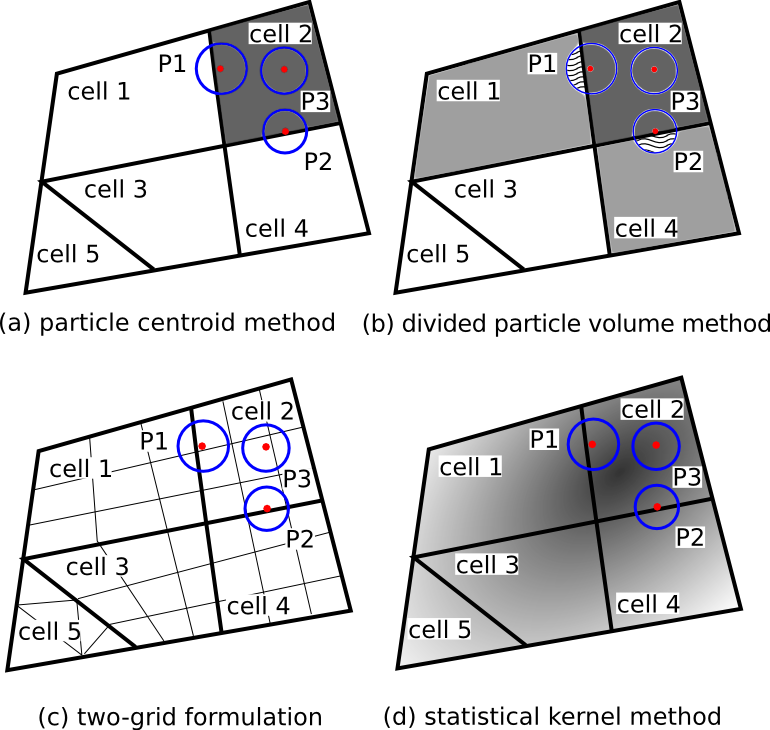
In the particle centroid method, only the particles whose centroids fall within a cell are counted for calculating the coarse grained continuum quantities (e.g., solid volume fraction , solid phase velocity , drag force ) for this cell. For simplicity we use here the calculation of to illustrate the difference among the averaging methods. The averaging of other variables such as solid phase velocity and drag forces can be performed in the same way. In the configuration illustrated in Fig. 1(a), with the PCM all the particles, P1, P2, and P3, are counted towards the solid volume fraction of cell 2. All other cells have zero solid volume fraction. It can be seen that when the particle centroid is located near cell boundaries (e.g., particle P2 in Fig. 1(a)), the error can be up to 50% (Peng et al., 2014). If a cell contains several such particles and if these particles are large compared to the host cell, unphysically large values can occur for this cell, leading to a non-smooth solid particle volume field with large gradients. Such non-smoothness in the coarse grained fields often causes spurious features in CFD–DEM simulations. However, except for this drawback, this seemingly unsophisticated method works very well otherwise, particularly when the cells are large compared to particle diameters. Moreover, if done properly the PCM can be made to satisfy the conservation requirement specified above in a straightforward manner. Finally, its implementation is straightforward even in parallel CFD solvers with unstructured meshes. As such, the PCM is one of the most widely used averaging procedures in the literature (e.g., Zhu and Yu, 2003).
2.3 Divided Particle Volume Method
The divided particle volume method was proposed by Wu et al. (2009b, a) to address the above-mentioned drawbacks of the particle centroid method caused by particles intersecting multiple cells. It is also referred to as analytical method in the literature (Peng et al., 2014). Instead of counting the entire particle volume to the cell containing its centroid, in DPVM a particle’s volume is divided among all cells it overlaps, with each cell receiving the actual volume inside it. This is illustrated in Fig. 1(b). The volume of particle P1 is divided between cells 1 and 2, with cell 1 sharing the shaded portion. The volume of particle P2 is similarly shared between cells 4 and 2. It has been demonstrated (Peng et al., 2014) that the dividing particle volume method gives much smoother coarse grained solid volume fraction field than the PCM does, and the corresponding CFD–DEM results were significantly improved as well. However, in unstructured CFD meshes where cells can be of arbitrary shape, dividing particle volumes among intersecting cells requires accounting for many scenarios, which is tedious to implement. Even for a three-dimensional Cartesian mesh with cubic cells (the simplest mesh one can hope for in practical CFD simulations), there are several particle–cell intersecting scenarios to account for. Theoretically, DPVM works for arbitrary meshes, structured or unstructured, with any elements shapes as long as any edge of the cell has a length larger than the particle diameter. While Wu et al. (2009b, a) implemented a DPVM for typical cells shapes (e.g., tetrahedra and wedge) based on a commercial finite volume CFD solver, a DPVM implementation that is general enough to accounts for all cell shapes (e.g., an arbitrary combination of general polyhedra) is a daunting challenge for most CFD practitioners. We are not aware of any such implementations beyond those by Wu and his co-workers (Wu et al., 2009b, a, 2014; Peng et al., 2014). Moreover, if the mesh contains small cells with sizes comparable to or smaller than some large particles, the analytical method would still lead to unphysically large solid volume fractions in these small cells.
2.4 Two-Grid Formulation
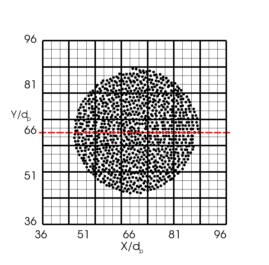
Another recent attempt to address the deficiency of the PCM in the cases of small cell-size to particle diameter ratios was made by Deb and Tafti (2013). Their idea was to use a separate mesh for the averaging and another mesh for the CFD simulation. The two meshes are constructed independently. Specifically, the averaging mesh is chosen based on particle diameters to ensure that the cell sizes are larger than particle diameters (they used ), and the CFD mesh is chosen according to the flow resolution requirements. They used structured Cartesian meshes similar to the one shown in Fig. 11(a), and Fig. 1 represents our interpretation of how it will be generalized to unstructured meshes. As can be seen from Fig. 11(c), each cell in the coarse graining mesh (displayed in thicker lines), contains exactly fluid mesh cells (thin lines). This configuration with aligned cell boundaries simplifies the implementation dramatically, and it is relatively easy to achieve on a structured Cartesian mesh. In parallel CFD solvers with unstructured meshes, however, the implementation of the two-grid formulation is not straightforward. For these solvers, using two meshes with arbitrarily aligned cells would increase the complexity of the implementation and necessitate non-trivial interpolations between the two meshes. Alternatively, to ensure alignment of averaging mesh cells and CFD cells, the latter of which may be of arbitrary shape, one can construct a coarsened mesh based on a fine CFD mesh via agglomeration. In fact, mesh agglomeration is common in geometric multi-grid methods for linear equation systems (Nishikawa and Diskin, 2011), which is used in many general-purpose unstructured CFD solvers. Such a fine CFD mesh and the corresponding agglomerated coarse mesh is shown schematically in Fig. 1(c). However, agglomeration across processor boundaries in parallel computing is not easy to implement, and in multi-grid methods for linear system the agglomeration is generally not performed across cells on different processors (Nishikawa and Diskin, 2011). Restricting agglomeration within the mesh on the same processor would impose serious limitations on the effectiveness of the two-grid formulation. Recently, Su et al. (2015) proposed a dual-mesh method CFD–DEM with conservation of mass and momentum guaranteed, but they did not discuss issues related to parallel implementations. Jing et al. (2015), on the other hand, used porous sphere model to handle large particles in the system to avoid unphysically large volume fractions.
2.5 Statistical Kernel Method
Yet another class of averaging methods are based on statistical kernel functions, which will receive a more thorough discussion here since it is the foundation for the method proposed in this work.
2.5.1 Formulation for Particles in Interior Cells
In the statistical kernel method the volume of each particle is distributed to the entire domain according to a weight function called kernel function . This is illustrated in Fig. 1(d). The solid volume fraction at location consists of the superposition of the distributed volumes from all particles, i.e.,
| (2) |
where is the weight function for particle . Possible choices of kernel functions include top hat function (with which the method essentially degenerates to PCM), Gaussian distribution function (Xiao and Sun, 2011; Glasser and Goldhirsch, 2001), and Johnson’s distribution function (Johnson, 1949; Zhu and Yu, 2002). The Gaussian kernel function is of particular interests to the current study due to its analytical tractability. In three-dimensional space the Gaussian kernel function for particle is:
| (3) |
where superscript indicates vector transpose; is the bandwidth of the Gaussian kernel, indicating the size of the region influenced by the particle (i.e., the cells whose solid volume fractions “receives” contribution from the particle); is the location of particle . Note that for the averaging procedure to have the conservation property, the kernel function must satisfy the normalization condition, i.e.,
| (4) |
where is the entire three-dimensional spatial domain. The Gaussian distribution function as in Eq. (3) is known to satisfy this condition. As pointed out by Zhu and Yu (2002), in addition to the normalization requirement, a kernel function should have local, finite, and compact support, i.e., it is nonzero only at a finite region in the neighborhood of the peak. Although the Gaussian distribution function has an infinite support theoretically, over 99% of the weight distribution is contained within a sphere of radius , which can be considered as the effective support of the kernel. In numerical codes such as CFD–DEM solvers, the Gaussian kernel can be considered as a function with effective local support (Sun et al., 2009).
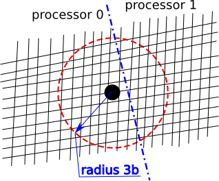
Statistical kernel based averaging is a theoretically elegant method for coarse graining from the discrete particle phase to a continuum descriptions of granular flows (Zhu and Yu, 2002; Babic, 1997). It resembles the technique used to bridge molecular dynamics in micro-scales and continuum mechanics in macro-scales. Zhu and Yu (2002) demonstrated that with the statistical averaging one can derive from the equations at the DEM level to a continuum level balance equation for the granular flow. Posterior tests showed good performance of the scheme by using the Johnson’s distribution function. However, its implementation in CFD–DEM solvers is not trivial since the volume of a particle are distributed not only to local cells, but also to nonlocal cells that may be located many layers of cells away from the particle location (e.g., those inside the dashed circle in Fig. 2), some of which may be even located on another processor. Searching for these cells in unstructured meshes is challenging, since the stored connectivity information in unstructured meshes normally only allows each cell’s immediate neighbors to be found. To find information of cells further away, one needs to find the immediate neighbors, and then find the neighbors of all immediate neighbors, and repeat this process recursively until all the cells “receiving” the volume of the particle are identified (Xiao and Sun, 2011). This process needs to be repeated for the volume distribution of each particle. The recursive nature of these search operations makes them time-consuming, although it is performed only once in the beginning of the simulation if the mesh does not move during the simulation. More importantly, the need for particles to communicate to non-local cells makes it challenging for implementations in parallel solvers based on MPI (Message Passing Interface) (Walker et al., 1996), a technology that is utilized by most modern CFD solvers (e.g., Duggleby et al., 2011).
2.5.2 Treatment of Physical Boundaries (Walls)
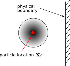
The scheme in Eq. (3) is applicable for particles in the interior cells. That is, particles that are “far away” from wall boundaries, i.e., those whose influence regions do not insect with boundaries. This scenario is depicted in Fig. 3. Here we are only concerned with physical boundaries of the system, i.e., mostly wall boundaries, although symmetry plane boundaries can be treated in the same way. Computational boundaries such as inter-processor boundaries are not considered since they should not pose theoretical difficulties.
For particles that are located near wall boundaries, Zhu and Yu (2002) modified the kernel function in Eq. (3) to the following:
| (5) |
where is the location of the image of the particle located at with respect to the physical boundary, shown in Fig. 4(b). They showed that the modified kernel function also satisfies the normalization condition in Eq. (4). This modification has a straightforward physical interpretation as illustrated in Fig. 4. When a particle is close to the physical boundary, if the kernel function as in Eq. (3) were used, part of the volume (indicated as wavy pattern in Figs. 4(a) and 4(b)) would be distributed to regions outside the physical domain. In view of the normalization condition Eq. (4), this would violate the conservation principle, since the integration domain does not cover the entire space. It can be seen that the kernel function adds the same amount that is distributed outside the physical domain by the kernel function to inside the domain (the shaded region in Fig. 4(b)), exactly compensating for the lost part and thus restoring the conservation. Although other methods such as renormalization can also restore the conservation (Xiao and Sun, 2011; Ries et al., 2014), the image kernel method is clearly more physical and elegant.
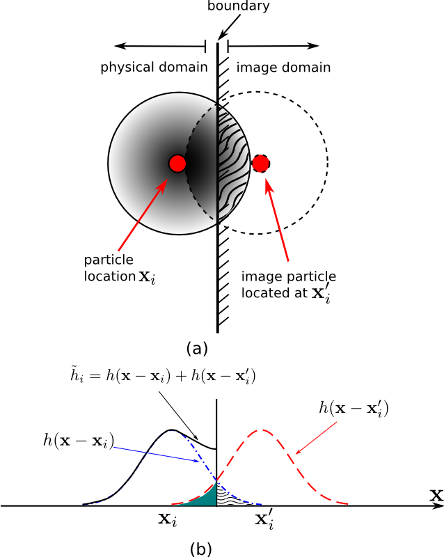
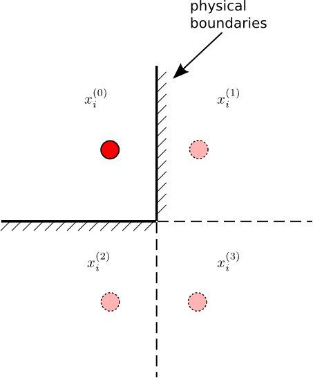
Although not explicitly treated by Zhu and Yu (2002), the method of images above as in Eq. 5 can be extended to treat more complex boundaries. The most straightforward extension is to account for the present of two boundaries, e.g., a particle located at the corner in a two-dimensional domain, as illustrated in Fig. 5(a). In this case the modified kernel function consists of four terms, with one associated with the physical particle and three with image particles. The kernel function for particle is thus
| (6) |
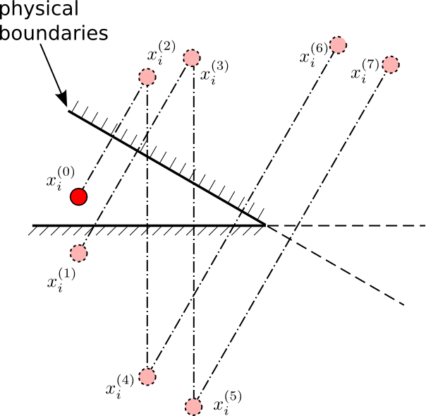
where is the index of the terms in the series, with being the physical kernel and other being image kernels. For a three-dimensional corner, the total number of terms in the kernel function would be eight, with one physical kernel and seven image kernels. Graphical illustration for this case is omitted here. For all the three cases above, the modified kernel functions satisfy the normalization requirement exactly regardless of the kernel bandwidths and the distances between the particle and the boundaries, thanks to the orthogonality of the boundaries in the two- and three-dimensional cases. For a particle located near multiple boundaries that are non-orthogonal, a scenario that can be encountered in complex geometries, the exact expression for the modified kernel function consists of an infinite series:
| (7) |
where is the index of the individual kernels, with centered at the physical particle and (where ) centered at the image particles. This is illustrated in Fig. 5(b), showing the locations of the physical kernel and the first seven image kernels. Since the kernels have finite support (bandwidth), the image kernels in the series located far away outside the computational domain can be safely truncated without impairing the accuracy. In spite of this, it can be seen that the complexity of the kernel function associated with a near-boundary particle, particularly for one that is located near a corner with several non-orthogonal boundaries, is significant. Indeed, averaging strategy near boundaries is an important and difficult subject that has been the focus of several recent publications (Ries et al., 2014; Weinhart et al., 2012). On the other hand, we point out that, at least in the context of CFD–DEM simulations, this difficulty related to boundaries is unique to sophisticated averaging schemes such as the statistical kernel method, as the presence of boundaries hardly poses any difficulties for the relatively simple averaging schemes such as PCM and DPVM, although in some cases they can make it difficult to construct a coarse graining mesh in the two-grid formulation.
2.6 Overview of Proposed Diffusion-Based Coarse Graining Method
In this work, we propose a diffusion-based coarse graining method consisting of the following two steps (using again the solid volume fraction as example):
-
1.
Perform averaging based on the particle centroid method to obtain the coarse grained field, denote the field as ); and
-
2.
Integrate a transient, homogeneous diffusion equation for a period of pseudo-time , using the field as initial condition and no-flux conditions on all physical boundaries. The obtained field is the coarse grained field.
In the rest of the paper we will show that this scheme is theoretically equivalent to the statistical coarse graining method presented in Section 2.5, and the pseudo time-span is determined according to the bandwidth of the kernel function. The equivalence is valid even with the presence of boundaries, and no special treatment for boundaries is needed in the proposed method. We will further demonstrate the following merits of the proposed method:
-
1.
Straightforward implementation in almost any CFD code by solving a few additional diffusion equations;
-
2.
Ability to obtain smooth coarse grained fields even with cell sizes comparable or slightly smaller than particle diameters; and
-
3.
Relatively mesh-independent; and
-
4.
No additional difficulties in implementations in parallel CFD solver using unstructured mesh with arbitrary cell shapes.
The advantages and limitations of the averaging methods reviewed above are summarized in Table 1.
| coarse-graining methods | implementation in generic CFD solvers(a) | smoothness for small (b) | mesh convergence | treatment of physical boundaries |
|---|---|---|---|---|
| PCM | easy | poor | poor | easy |
| DPVM | difficult | moderate(c) | poor | easy |
| statistical kernel | moderate | good | good(d) | difficult |
| two-grid | difficult | moderate | good(d) | moderate |
| current method | easy | good | good(d) | easy |
(a) a parallel CFD solver based on unstructured mesh with cells of arbitrary shapes and
connectivity
(b) indicates cell-size to particle diameter ratio, where is mesh
cell size, and is particle diameter
(c) if is approximately 2 or larger
(d) if the kernel bandwidth (or coarse graining mesh size) is chosen independent of the CFD mesh
cell size
3 Diffusion-Based Coarse Graining Algorithm
3.1 Summary and Heuristic Reasoning
In the particle centroid method, the averaging from Lagrangian particle data to Eulerian mesh-based field (e.g., solid volume fraction) is done as follows. We loop through all cells, and for each cell we sum up all the particles volume to their host cells (defined as the cell within which the particle centroid is located) to obtain the total particle volume in each cell. The solid volume fraction of each cell is then obtained by dividing the total particle volume in the cell by the total volume of the cell . That is,
| (8) |
where is the number of particles in cell , which implies that . Multiplying both sides of Eq. (8) by and taking summation over all cells, the conservation requirements in Eq. (1) can be recovered. Therefore, the PCM-based averaging is conservative by construction.
As mentioned in Section 2.2, the coarse grained fields so obtained may have large gradients. The cells with large solid volume fraction are shown schematically as three box-car functions in Fig. 6. The ticks indicate cell centers. To address this issue of non-smoothness, a straightforward idea is to smooth this field via diffusion, i.e., by solving a diffusion with non-smooth fields as initial conditions. The diffusion equation essentially redistributes particle volumes within the field while automatically conserving total solid volume in the domain during the diffusion. To ensure conservation of mass, no-flux (i.e., zero gradient) conditions should be specified at all physical boundaries except for periodic boundaries, where periodic conditions should be used instead. The smoothened field so obtained is shown in Fig. 6 as thick dashed line.
3.2 Equivalence to Statistical Kernel Method
3.2.1 Particles in Interior Cells
Consider the diffusion equation for in the three-dimensional free space:
| (9) | ||||
| (10) |
where are spatial coordinates; can be considered as solid volume fraction , but the derivations below are valid for other coarse-grained quantities (e.g., and ) as well. Diffusion equations are independently solved for each component when the coarse grained fields are vector- and tensor-fields. For simplicity, the subscript of is omitted in this subsection. in the Cartesian coordinate; is a square integrable function; is pseudo-time (time multiplied with a unit diffusion coefficient), which should be distinguished from the physical time in the CFD–DEM formulation. To solve the problem above, we recall that the fundamental solution (also called Green’s function) of the diffusion equation in free space is (e.g., Haberman, 2012, Chapter 11):
| (11) |
which is basically the solution to Eq. (9) with the initial condition , with being Dirac delta function. Based on the Green’s function, the solution to Eq. (9) with initial conditions in Eq. (10) is:
| (12) |
Consider the initial condition consisting of a linear combination of shifted delta functions centered at , where , that is,
| (13) |
where are multiplier coefficients for each shifted delta function. The interpretation of as particle volume and as number of particles will be evident shortly. Plugging in Eq. (13) to Eq. (12) yields the solution to the diffusion equation (9) with the initial condition of superimposed shifted delta functions:
| (14) |
which is a linear combination of the Green functions. This is illustrated in Fig. 6.

Consider the solution at a fixed pesudo-time , denoted as . The solution is rewritten as:
| (15) |
where
| (16) |
Comparing Eqs. (15) and (16) with Eqs. (2) and (3), the equivalence between diffusion based and the statistical kernel based coarse graining is established with . The physical interpretation is that given particles centered at with volume , the following two ways of calculating solid volume fraction field are equivalent:
-
1.
compute the solid volume fraction field by using the PCM, and solve Eq. (9) until with as initial condition; and
- 2.
3.2.2 Treatment of Physical Boundaries
The equivalence shown above holds for interior domains where boundary effects are not present. For particles near boundaries, we consider the same diffusion equation as Eq. (9) on a semi-infinite domain , where is the equation of the boundary plane. Zero-gradient Neumann boundary condition, i.e., , is specified at the boundary, where is the normal direction of the plane.
The solution to Eq. (9) at time with initial condition
can be obtained by constructing a Green’s function that satisfy the zero-gradient condition on the boundary plane. It turns out that such a Green’s function, denoted as , can be found by the method of images (Haberman, 2012):
| (17) | ||||
| (18) |
where is the image of with respect to the boundary plane . The solution to the diffusion equation on a domain bounded by plane is:
| (19) |
Clearly, the solution is equivalent to the kernel function in Eq. (5) when .
The equivalence can be extended to the general case where the domain is bounded in all three directions and a particle is located near the corner, i.e., it is close to many, possibly non-orthogonal boundary planes (see Fig. 5). On such a domain, with no-flux boundary conditions the Green’s function for the diffusion equation is a summation of infinite series (Haberman, 2012):
| (20) |
which corresponds exactly with the summation of infinite series of kernel functions in Eq. (12). This is not surprising since this solution is obtained with the method of images, which is the same idea based on which the kernel function in Eq.(12) is obtained. In summary, the diffusion-based averaging procedure as described in Section 3.1 is theoretically equivalent to the statistical kernel method presented in Section 2.5.
Numerically the equivalence between the two methods holds up to the mesh discretization accuracy. If the mesh used to obtain is sufficiently small, or equivalently, if the initial condition obtained via PCM used for the diffusion equation is approximately a linear combination of shifted delta functions corresponding to individual particles, then the two methods are numerically equal. We emphasize that the diffusion-based method can handle both particles in the interior domain and those near the boundaries in a unified manner, i.e., by solving a diffusion equation with no-flux boundary conditions. The equivalence to statistical kernel function is valid for domains of arbitrary shapes, for both interior particles and particles close to arbitrary boundaries. This characteristics of the current method distinguishes itself from its theoretically equivalent counterpart, the statistical kernel-based averaging, where obtaining the Green’s functions for particles located near corners in a generic three-dimensional domain can be tedious.
4 A Priori Numerical Tests
In this section, the diffusion-based averaging algorithm described in Section 3 is used to obtain coarse grained solid volume fraction fields given a quasi-random distribution of particles in the computational domain. Note that even though we occasionally refer to “CFD mesh” in the text, no CFD or DEM simulations are performed in these tests, and the particles do not move.
In Section 4.1, we first compare the coarse grained fields obtained by using the diffusion-based method and those obtained with Gaussian kernel functions to verify the theoretical equivalence of the two shown in Section 3.2. In some CFD–DEM simulations, the flow field resolution requirements may necessitate using cells that are comparable to or smaller than the particle diameters in certain regions. As a consequence, using CFD mesh for averaging as is done in PCM and DVPM can lead to two potential problems: unphysically large in small cells and mesh-dependent fields. To demonstrate the merits of the proposed method, tests in Sections 4.2–4.4 aim to show its capabilities to produce smooth coarse grained fields on meshes with small cells, to handle stretched and unstructured meshes, and to produce mesh-independent results. Comparisons are made with other averaging methods when applicable.
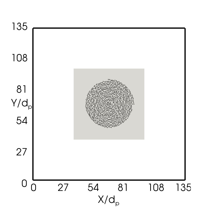
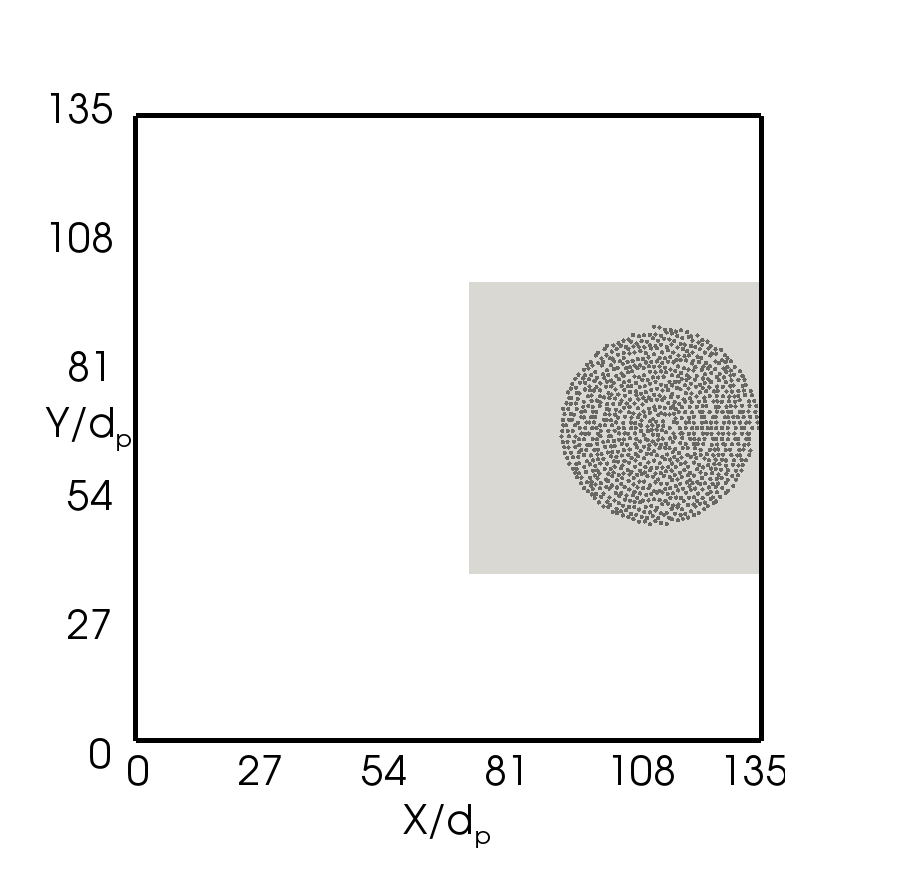
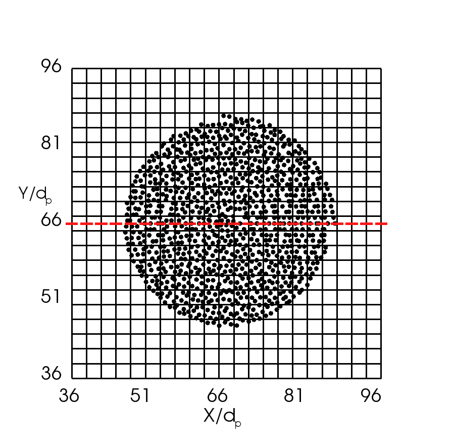
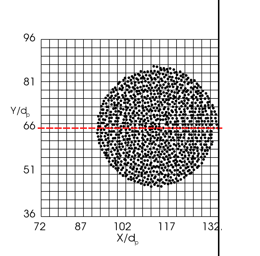
All simulations presented below are performed with 1000 spherical particles with quasi-random spatial distribution in the computational domain. In the verification tests presented in Section 4.1, two representative distributions of particles are used to evaluate the performance of the proposed method for particles located in interior cells and those located near boundaries. The two configurations are displayed in Figs. 7(a) and 7(b), respectively. In both cases the sizes of the domain are , where and are the dimensions in and directions, respectively. Simulations are performed on meshes with only one layer of cells in -direction. The thickness of the cells is the same as the particle diameter, and all particles are located on the same plane normal to the -axis. No-flux conditions are specified at all boundaries to ensure conservation of particle mass in the coarse graining procedure.
4.1 Verification of Equivalence to Gaussian Kernel Averaging
In this test, solid volume fraction field is obtained from the particle distribution by using both statistical kernel averaging and the diffusion-based method to demonstrate the equivalence between the two. The mesh resolution is , where and are the numbers of cells in and directions, respectively. The bandwidth used for the statistical kernel method is , and the corresponding diffusion time is for the diffusion-based method according to . This test is performed for both interior particles and near-boundary particles.
For interior particles, the solid volume fraction fields along the centerline of the domain (indicated by the dashed line in Fig. 8(a)) obtained by using both methods are displayed in Fig. 8. The domain of interest (shaded region in Fig. 7(a)) is shown in Fig. 8(a), and the coarse grained fields are presented in Fig. 8(b). It can be seen that the fields obtained by using statistical kernel-based averaging and that by using the diffusion-based method agree very well. For the configuration with particles located near boundaries as shown in Fig. 7(b), the mesh and detailed particle distribution are shown in Fig. 9(a), and Fig. 9(b) displays the fields obtained by using both methods. Again, that the coarse grained fields in the simulation using both methods are consistent.
From the results above, it can be seen that the statistical kernel method with Gaussian kernels and the proposed method are indeed equivalent for both interior and near-boundary particles. Note that the boundary effect is accounted for in the Gaussian kernel averaging by using the image kernels in Eq. (5). While the kernal function in the statistical kernel method needs to be modified to accommodate the proximity of particles to the boundary (see Section 2.5.2), the diffusion-based method remains the same for both the interior and the near-boundary particles by using no-flux boundary conditions. This simplicity in formulation and implementation is an important improvement of the proposed method over statistical kernel-based averaging method.


4.2 Comparison with Existing Coarse Graining Methods
To demonstrate the advantages of the diffusion-based coarse graining method, the comparison of the diffusion-based method with PCM, DPVM, and two-grid formulation is performed. The set-up and parameters, including the computational domain, mesh resolution, particle distribution, bandwidth, diffusion time are the same as in Section 4.1. Since the performances of these coarse graining methods are similar for both interior and near-boundary particles, only the results for interior particles are presented below.
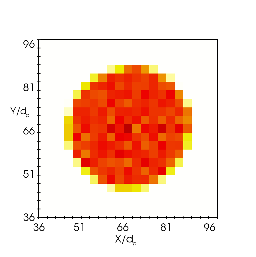
Figure 10 shows the comparison of the fields obtained by using PCM, DPVM, and the diffusion-based method. It can be seen that the largest in the field computed by PCM is 0.64, which is clearly unphysical as it exceeds the maximum possible value (0.606) for close-packed spherical particles in a two-dimensional domain (Chang and Wang, 2010). This is attributed to the inaccuracy of the PCM when the centroid of a particle is located near the boundaries of a cell as discussed in Section 2.2. The maximum value in the DPVM results is smaller than that of PCM, since the volume of a particle is divided among all cells it intersects with. Although the field obtained by using DPVM is smoother than the PCM results, the overall fluctuations and gradients are still large. Considering the statistically uniform particle distribution in the domain, which is evident from visual observations of Fig. 8(a), these fluctuations cannot be justified physically, and thus are considered artifacts introduced by the averaging procedure. In contrast, the field obtained by using the diffusion-based method is much smoother with a flat region in the middle (between = 50 and 80), confirming the visual observation of statistically uniform particle distribution near the core of the region occupied by the particles.

The comparison of diffusion-based method and two-grid formulation is presented in Fig. 11. The configuration of the coarse graining mesh is displayed in Fig. 11(a), showing that each cell in the coarse graining mesh contains exactly CFD cells. From the profiles along the horizontal centerline presented in Fig. 11(b), both methods are able to produce smooth solid volume fraction fields that are consistent with each other. Noted that the resolution of the coarse graining mesh for two-grid formulation is lower than that of the CFD mesh (with much larger cells), which explains why the results obtained by with the diffusion-based method is smoother. The values on the CFD mesh is not directly obtained, and interpolations (also called mapping) from the coarse-graining mesh to the CFD mesh are needed to obtain in CFD cells (Deb and Tafti, 2013). Linear interpolation is used to obtain the results presented in Fig. 11(b). In contrast, in the diffusion-based method the coarse grained field is obtained directly on the fine mesh without the need of interpolations between two meshes. Another problem in the implementation of the two-grid formulation is the agglomeration of the unstructured mesh, which has been discussed in Section 2.4. Therefore, despite the fact that the two methods give consistent coarse grained fields in this case, we argue that the diffusion-based method is preferred when used in general CFD solvers due to its straightforward implementation on arbitrary meshes.
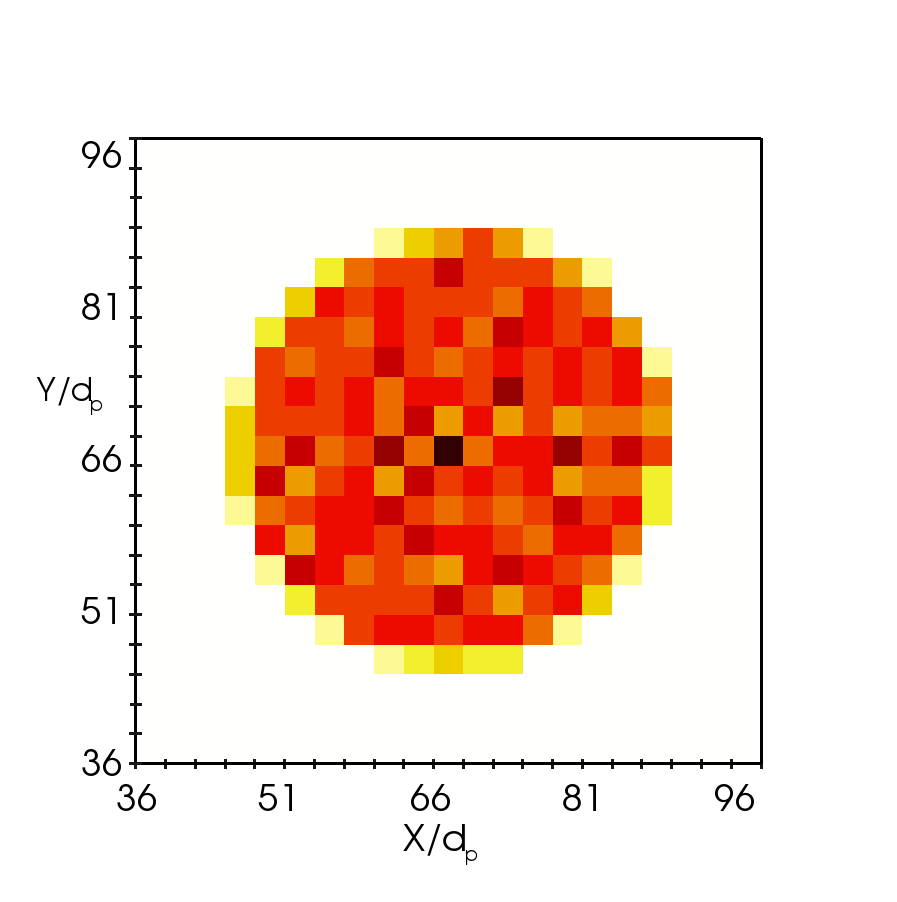
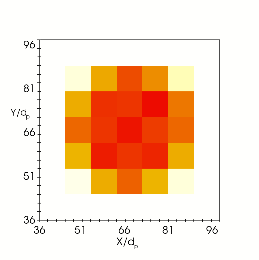
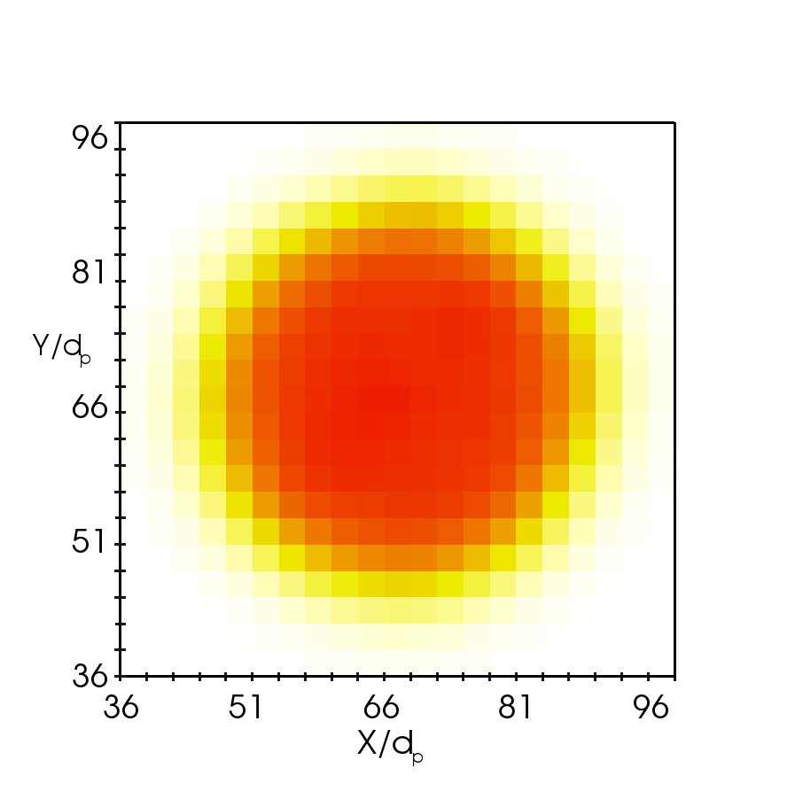
To summarize the comparison, solid volume fraction contours in the two-dimensional domain obtained by using the four methods, PCM, DPVM, two-grid formulation, and diffusion-based method, are presented in Fig. 12. In these plots, each cell is colored according to the corresponding value in the cell, and no interpolations are used to obtain the contours. Consequently, the meshes used in each case (presented above) are clearly distinguishable from the plots. As is evident from the contours, extreme high or low values (and thus large gradients) are most frequent in the PCM results, and also occasionally occur in the DPVM result. In contrast, no such extreme values are present in the plot obtained with the two-grid formulation and that from the diffusion-based method. In the two-grid formulation result, all CFD cells in the same coarse graining cell have the same value due to the simple mapping scheme used (following Deb and Tafti (2013)).


4.3 Averaging on Stretched and Unstructured Meshes
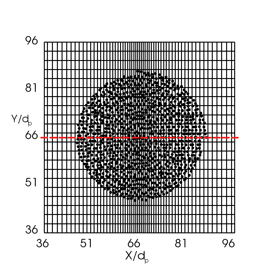
In this subsection, the performance of the diffusion-based averaging method is evaluated on a stretched mesh and an unstructured mesh with triangular cells. These types of meshes are commonly used in industrial CFD simulations. Since these highly irregular meshes pose difficulties in the averaging procedure, this is an illustration of the merits of the diffusion-based method. The computational set-up and parameters are the same as used in Section 4.1. The coarse grained field obtained by using the uniformly spaced mesh presented in Fig. 8(a) is used as benchmark solution for comparison purposes.
Figure 13(a) shows the particle locations on top of the stretched mesh. The mesh has cells with progressive refinement in -direction towards the vertical centerline, and the stretch ratio, defined as the ratio between the widths of two adjacent cells, is 1.04. The coarse grained solid volume fraction along the horizontal center line is presented in Fig. 13(b). It can be seen that profile obtained by using the diffusion-based method on the stretched mesh are identical to that from the uniform mesh. This demonstrates the capability of the diffusion-based method in performing averaging on stretched meshes without causing computational artifacts.

The coarse graining test on an unstructured mesh with triangular cells are shown in Fig. 14. Figure 14(a) illustrates the particle distribution and the unstructured mesh, with a close-up view of part of the computational domain shown in the inset. The obtained solid volume fraction along the horizontal center line is shown in Fig. 14(b). It can be seen that the coarse grained profile obtained on the unstructured mesh is consistent with that obtained on the structured mesh.
It is worth mentioning that it would be difficult for other averaging methods to obtain smooth fields for stretched or irregular meshes as the ones shown in Figs. 13(a) and 14(a). Generally speaking, the methods that directly use the CFD mesh for averaging (e.g., PCM and DPVM) are more susceptible to the spatial variations (e.g., stretching) in the CFD meshes. In contrast, the methods that use an independent mesh or parameter for averaging (e.g., two-grid formulation and statistical kernel method, respectively) are more robust on stretched meshes. We note that while the proposed method uses the CFD mesh for averaging, the results are relatively independent of the CFD mesh. In summary, the two tests here suggest that the diffusion-based averaging method can produce smooth fields even on meshes with significant stretching and on unstructured meshes with very small cells.


4.4 Mesh Convergence Study
As stated in Section 2.1, a highly desirable property of a averaging algorithm is being able to yield mesh-independence averaged fields, where the mesh here refers to CFD mesh. Part of the mesh-independence has been studied in Section 4.3 above. This subsection focuses on the convergence of results on progressively refined meshes. As reviewed in Section 2 (see Table 1 for a summary), statistical kernel function methods and the two-grid formulation can give relatively mesh-independent results, since the bandwidth (for the statistical kernel methods) or mesh (for the two-grid formulation) used for averaging can be chosen independently of the CFD mesh. In contrast, PCM and DPVM use the CFD mesh for averaging, and thus the coarse grained fields so obtained inevitably depend on the CFD mesh used. The purpose of this test is to demonstrate the mesh convergence characteristics of the diffusion-based averaging method.
The particle distribution and the computational domain size are the same as above as shown in Fig. 7(a). The coarse grained fields are obtained by using the diffusion-based method with four successively refined meshes A, B, C, and D, the resolution and cell sizes for which are presented in Table 2. Note that in the finest mesh D, the volume of each cells is , which is only about half of the volume of a spherical particle of diameter . When the volume of a cell is smaller than the particle, and if PCM is used to obtain the solid volume fraction, the value would be larger than one for the cells in which the particle centroids are located; for DVPM, the cells that are fully occupied by a particle would have values equal to one. Even though such scenarios may only occur in a few cells, it can lead to very large fluid drag forces on the particles and on the fluid, ultimately destabilizing the simulation.
The coarse grained fields obtained by using the diffusion-based method on meshes A–D are presented in Fig. 15(a). It can be seen that the coarse grained fields along the horizontal centerline obtained with the three finer meshes B, C and D are identical (as demonstrated by the lines falling on top of each other), suggesting that mesh convergence is achieved. The very minor deviation of the results from mesh A () near is due to the slightly inadequate mesh resolution, and this is expected. Also note from Fig. 15 that unphysically large values do not appear in any of the coarse grained fields produced by the diffusion-based method, even for the finest mesh D (), which has cell volumes smaller than the volume of a single particle as explained above. For comparison purposes, the coarse grained fields obtained by using PCM and DPVM are presented in Figs. 15(b) and 15(c), respectively. Only the results from meshes A–C are shown for these two cases, and the results for mesh D are omitted. This is due to the presence of excessively large values on the mesh D results, and also because PCM and DPVM are not expected to work on meshes with cell dimensions smaller than the particle diameter. From Figs. 15(b) and 15(c) it can be seen that with PCM and DPVM the coarse grained solid volume fraction values exhibit more spatial oscillations as the mesh is refined, producing more extreme high and low values (e.g., high values over 0.7 and low values of 0 in mesh C for both cases). Mesh convergences is not achieved for either methods. Although it is not presented here, it is expected that the two-grid formulation should be able to give mesh-independent results, as long as the same mesh (e.g., mesh A) is used for as the coarse-graining mesh same for the all cases. In this case, the coarse-graining mesh would contain , , , and CFD cells, respectively, for cases A, B, C, and D.
Hence, from the results obtained in the mesh convergence test and those presented in Section 4.3, we can conclude that the diffusion-based method is able to produce smooth and mesh-independent coarse grained fields, even for very fine meshes with cells that are smaller than the particles or meshes with stretching. This is a significant advantage over PCM and DPVM, and would have profound implications in CFD–DEM simulations.
| mesh | and | and |
|---|---|---|
| A | 4 | |
| B | 2 | |
| C | 1 | |
| D | 0.5 |


5 Discussion
5.1 Implementation and Computational Overhead
The proposed averaging method involves solving transient diffusion equations with no-flux boundary conditions, which is straightforward and can usually take advantage of the existing infrastructure (e.g., discretization schemes, linear system solvers, parallel computing capabilities) available in the CFD solver. In this work, the implementation of the diffusion equation solver in OpenFOAM and its integration into the CFD–DEM solver needed only a few dozen lines of additional code. In particular, the no-flux boundary condition is easy to enforce without additional complexity in a finite-volume solver such as OpenFOAM. In finite-difference-based solvers, ghost nodes may be needed for discretization of the Laplacian operator. However, usually these special treatments are already in place in the CFD solver, and the ghost nodes are only limited to a few layers depending on the stencil width of the discretization scheme. This is in contrast to the “image” regions (see Fig. 4a) in statistical kernel methods, where the number of cell layers is of the order of (i.e., the ratio between bandwidth and cell size) and can be rather large when the cells are small.
A second-order central scheme was used for the spatial discretization in the diffusion equation; the Crank–Nicolson scheme was used for temporal integration. With this choice of discretization schemes the stability is guaranteed for any time step size due to the implicit nature of the time stepping. Therefore, the time step size is only restricted by the solution accuracy to be achieved. It is noted that the accuracy in solving the diffusion equations is not essential for the coarse graining. One can consider that an inaccurate temporal or spatial discretization of the diffusion equation leads to a solution corresponding to a modified equation, which may have a different diffusion constant (corresponding to a different kernel bandwidth) than specified, or even a different way of averaging. However, slight inaccuracies are acceptable, since the coarse graining scheme used to link microscopic and macroscopic variables is non-unique anyway. Hence, for the sake of reducing computational costs, large time step sizes can be used to solve the diffusion equations in the averaging.
In this study it was found that using only three or even one time step, i.e., a time step size of or , was sufficient. Figure 16 displays the coarse grained field obtained with different time step sizes = , , and . It can be seen that the fields obtained in the three case are almost identical. The particle configuration presented in Fig. 8(a) was used in this calculation. The number of time steps needed to solve the diffusion equation with a given accuracy also depends on the time span or the bandwidth . The bandwidth used in obtaining the results in Fig. 16 was . Bandwidths up to have been tested, and even with such a excessively large bandwidth, a time step size of or still yielded qualitatively similar results as presented in Fig. 16. The kernel bandwidth is a physical parameter usually specified based on the particle diameters . In particular, note that the bandwidth is chosen independent of the CFD mesh sizes.

5.2 Numerical Diffusion and Offset on Coarse Meshes
As pointed out in Section 3.2, the equivalence between the diffusion-based coarse-gaining method and the statistical kernel-based method holds rigorously only theoretically, i.e., when the CFD mesh is infinitely fine. The equivalence is not exact on meshes consisting of cells of finite sizes. Specifically, when the cell size is large compared to the diffusion bandwidth, numerical diffusions occur. Taking the calculation of solid volume fraction for example, if a particle resides in a relatively large cell (), the statistical kernel method assigns most of the particle volume to the host cell, but the diffusion-based coarse-graining method still assigns some volume to the neighboring cells via diffusion. This error is closely related to the ratio between the diffusion bandwidth and the cell size.
To study the numerical diffusion, we use a one-dimensional domain of length . The dimensions of the domain in height and transverse directions are both . A particle is co-located with the center of a cell at , as depicted in Fig. 17. Solid volume fractions are computed with the diffusion-based method and the statistical kernel method, the latter of which is obtained via analytical evaluations of the definite integral of the kernel in each cell and is thus considered as benchmark. Consistent with the setup in the test cases examined in Section 4, the diffusion bandwidth is chosen to be for both the diffusion-based method and the statistical-kernel method. Four cell sizes and are investigated, corresponding to bandwidth/cell size ratios of , , , and , respectively. The obtained solid volume fractions are presented in Fig. 18.


It can be seen that the discrepancy between the diffusion-based method and the statistical kernel method, which can be considered as numerical diffusion, are almost negligible for and . The numerical diffusion is appreciable for (), but this level of diffusion is likely to be acceptable for most applications. For , the numerical diffusion is significant and is probably unacceptable. In practice, however, such a small bandwidth (or large cell size) is uncommon.
To further quantify the amount of numerical diffusion, we define a metric , where is the area between the analytical solution (from the statistical kernel method) and the numerical solution (from the diffusion-based method) around the peak, as indicated by the shaded area in Fig. 18(d), and is the total area under the analytical solution curve. If the numerical solution is identical to the analytical solution, then ; if the numerical solution is completely diffused to the entire domain, then is approximately for a domain that is very large (compared with the diffusion bandwidth). The results for the four cases presented in Fig. 18 are evaluated with the metric defined above, and we obtained , and , respectively, for , and . A correlation between and can be established from this investigation. In practical simulations, the ratio is known in the entire field, which can then be used to infer and to assess the possible extent of numerical diffusion before actual simulations are performed. If numerical diffusion is a concern, in regions with large cells one can simply degenerate to PCM , which is particularly suitable for large cells. Within the proposed framework, the degeneration can be straightforwardly achieved by locally setting the diffusion constant (discussed above in Section 5.1) to very small values in the regions of concern. Conservation would still be guaranteed in the diffusion-based averaging.
Another limitation of the proposed coarse-graining method is that it does not distinguish the specific locations of the particles within its host cell. Instead, all particle volumes are first lumped to the host cell center as in the PCM, and then the obtained field is used as initial condition to solve the diffusion equation. This limitation is directly inherited from the PCM. Potentially, the obtained volume fraction distribution may have an offset error, and the amount of offset for a particular particle can be as large as the distance from the furtherest point in the host cell to the cell center. However, when there are a large number of particles randomly distributed in the domain, the offset errors associated with individual particles tend to cancel. This is rarely a concern in most simulations, and it decreases with mesh refinement.
6 Conclusion
In this work, we proposed a coarse-graining algorithm based on solving diffusion equations with no-flux boundary conditions. The coarse graining method is valuable for coupled continuum–discrete solvers such as CFD–DEM solvers for dense particle-laden flows. The proposed algorithm can be straightforwardly implemented in any parallel, three-dimensional mesh-based CFD solvers developed for industrial flow simulations on complex geometries. Via theoretical analysis we demonstrated that the proposed method was equivalent to the statistical Gaussian kernel-based coarse graining method. The equivalence is established for both interior particles and particles near boundaries, and is valid for domains of arbitrary domain shapes up to the mesh discretization accuracy. The theoretical equivalence was verified by using several a priori numerical tests. It was further demonstrated that the proposed algorithm was able to yield physically reasonable, spatially smooth coarse grained fields on stretched meshes, unstructured meshes, and meshes having cells with volumes smaller than the volume of a particle. Moreover, numerical tests on successively refined meshes showed that the diffusion-based coarse graining method was able to produced mesh-independent results, which is an important advantage over many existing coarse graining methods such as the particle centroid method and the divided particle volume method.
In summary, the merits of the proposed coarse graining method include (1) sound theoretical foundation, (2) unified treatment of interior and near-boundary particles within the same framework, (3) guaranteed conservation of relevant physical quantities (e.g., particle mass in the cases demonstrated) in the coarse graining procedure, (4) easy implementation in CFD solvers with almost arbitrary meshes and ability to produce smooth and mesh-independent coarse-grained fields on unfavorable meshes, and (5) easy parallelization by utilizing the existing infrastructure in the CFD solver.
The diffusion-based coarse graining method has been implemented into a CFD–DEM solver. We emphasize that caution should be exercised when using this method in CFD–DEM solvers. In particular, the diffusion should be applied on the momentum and not on the velocities. Detailed derivations and CFD–DEM simulation results obtained with the coarse graining method proposed here are presented in (Sun and Xiao, 2015).
7 Acknowledgment
The computational resources used for this project were provided by the Advanced Research Computing (ARC) of Virginia Tech, which is gratefully acknowledged. Authors gratefully acknowledge partial funding of graduate research assistantship from the Institute for Critical Technology and Applied Science (ICTAS, grant number 175258) in this effort. We thank the Dr. Chunliang Wu of ANSYS for his comments, which helped improving the quality of the manuscript.
References
- Anderson and Jackson (1967) Anderson, T., Jackson, R., 1967. A fluid mechanical description of fluidized beds: Equations of motion. Industrial and Chemistry Engineering Fundamentals 6, 527–534.
- Babic (1997) Babic, M., 1997. Average balance equations for granular materials. International Journal of Engineering Science 35 (5), 523–548.
- Belytschko et al. (2002) Belytschko, T., Xiao, S., Schatz, G., Ruoff, R., 2002. Atomistic simulations of nanotube fracture. Physical Review B 65 (23), 235430.
- Belytschko and Xiao (2003) Belytschko, T., Xiao, S. P., 2003. Coupling methods for continuum model with molecular model. International Journal for Multiscale Computational Engineering 1 (1), 115–126.
- Calantoni et al. (2004) Calantoni, J., Holland, K. T., Drake, T. G., 2004. Modelling sheet-flow sediment transport in wave-bottom boundary layers using discrete-element modelling. Philosophical Transactions of Royal Society of London: Series A 362, 1987–2002.
- Chang and Wang (2010) Chang, H. C., Wang, L. C., 2010. A simple proof of Thue’s theorem on circle packing. arXiv preprint arXiv:1009.4322.
- Chen et al. (1991) Chen, S., Chen, H., Martnez, D., Matthaeus, W., 1991. Lattice-Boltzmann model for simulation of magnetohydrodynamics. Physical Review Letters 67 (27), 3776–3780.
- Cundall and Strack (1979) Cundall, P., Strack, D., 1979. A discrete numerical model for granular assemblies. Géotechnique 29, 47–65.
- Curtin (2013) Curtin, W., 2013. Methods for multiscale quantum/atomistic coupling. In: Müser, M. H., Sutmann, G., Winkler, R. G. (Eds.), Hybrid Particle-Continuum Methods in Computational Materials Physics. Vol. 46. Forschungszentrum Jülich, p. 159.
- Deb and Tafti (2013) Deb, S., Tafti, D. K., 2013. A novel two-grid formulation for fluidparticle systems using the discrete element method. Powder Technology 246, 601–616.
- Delgado-Buscalioni et al. (2005) Delgado-Buscalioni, R., Coveney, P. V., Riley, G. D., Ford, R. W., 2005. Hybrid molecular-continuum fluid models: implementation within a general coupling framework. Philosophical Transactions of Royal Society of London: Series A 363 (1833), 1975–1985.
- Donev et al. (2010) Donev, A., Bell, J. B., Garcia, A. L., Alder, B. J., 2010. A hybrid particle–continuum method for hydrodynamics of complex fluids. Multiscale Modeling & Simulation 8 (3), 871–911.
- Drake and Calantoni (2001) Drake, T., Calantoni, J., 2001. Discrete particle model for sheet flow sediment transport in the nearshore. Journal of Geophysical Research: Oceans (1978–2012) 106 (C9), 19859–19868.
- Duggleby et al. (2011) Duggleby, A., Camp, J. L., Doron, Y., Fischer, P. F., 2011. Massively parallel computational fluid dynamics with large eddy simulation in complex geometries. In: ASME 2011 International Mechanical Engineering Congress and Exposition. American Society of Mechanical Engineers, pp. 817–824.
- Eidel (2009) Eidel, B., 2009. Coupling atomistic accuracy with continuum effectivity for predictive simulations in materials research–the quasi-continuum method. International Journal of Materials Research 100 (11), 1503–1512.
- Esmaeeli and Tryggvason (1998) Esmaeeli, A., Tryggvason, G., 1998. Direct numerical simulations of bubbly flows. Part 1: Low Reynolds number arrays. Journal of Fluid Mechanics 377, 313–345.
- Esmaeeli and Tryggvason (1999) Esmaeeli, A., Tryggvason, G., 1999. Direct numerical simulations of bubbly flows. Part 2: Moderate Reynolds number arrays. Journal of Fluid Mechanics 385, 325–358.
- Glasser and Goldhirsch (2001) Glasser, B. J., Goldhirsch, I., 2001. Scale dependence, correlations, and fluctuations of stresses in rapid granular flows. Physics of Fluids 13 (2), 407–420.
- Guo and Curtis (2015) Guo, Y., Curtis, J. S., 2015. Discrete element method simulations for complex granular flows. Annual Review of Fluid Mechanics 47, 21–46.
- Haberman (2012) Haberman, R., 2012. Applied partial differential equations with Fourier series and boundary valve problems. Pearson Higher Ed.
- Han et al. (2003) Han, T., Levy, A., Kalman, H., 2003. DEM simulation for attrition of salt during dilute-phase pneumatic conveying. Powder Technology 129 (1), 92–100.
- Jing et al. (2015) Jing, L., Kwok, C. Y., Leung, Y. F., Sobral, Y. D., 2015. Extended CFD–DEM for free-surface flow with multi-size granules. International Journal for Numerical and Analytical Methods in Geomechanics.
- Johnson (1949) Johnson, N. L., 1949. Systems of frequency curves generated by methods of translation. Biometrika, 149–176.
- Kempe and Fröhlich (2012) Kempe, T., Fröhlich, J., 2012. Collision modelling for the interface-resolved simulation of spherical particles in viscous fluids. Journal of Fluid Mechanics 709, 445–489.
- Kempe et al. (2014) Kempe, T., Vowinckel, B., Fröhlich, J., 2014. On the relevance of collision modeling for interface-resolving simulations of sediment transport in open channel flow. International Journal of Multiphase Flow 58, 214–235.
- Mitchell and Griffiths (1980) Mitchell, A. R., Griffiths, D. F., 1980. The finite difference method in partial differential equations. John Wiley.
- Müller et al. (2008) Müller, C. R., Holland, D. J., Sederman, A. J., Scott, S. A., Dennis, J., Gladden, L., 2008. Granular temperature: Comparison of magnetic resonance measurements with discrete element model simulations. Powder Technology 184 (2), 241–253.
- Müller et al. (2009) Müller, C. R., Scott, S. A., Holland, D. J., Clarke, B. C., Sederman, A. J., Dennis, J. S., Gladden, L. F., 2009. Validation of a discrete element model using magnetic resonance measurements. Particuology 7 (4), 297–306.
- Müller (2013) Müller, M., 2013. Speeding-up particle simulations of multicomponent polymer systems by coupling to continuum descriptions. In: Müser, M. H., Sutmann, G., Winkler, R. G. (Eds.), Hybrid Particle-Continuum Methods in Computational Materials Physics. Vol. 46. Forschungszentrum Jülich, p. 127.
- Nishikawa and Diskin (2011) Nishikawa, H., Diskin, B., 2011. Development and application of parallel agglomerated multigrid methods for complex geometries. In: Proceedings of the 20th AIAA Computational Fluid Dynamics Conference.
- Peng et al. (2014) Peng, Z., Doroodchi, E., Luo, C., Moghtaderi, B., 2014. Influence of void fraction calculation on fidelity of CFD-DEM simulation of gas–solid bubbling fluidized beds. AIChE Journal 60 (6), 2000–2018.
- Piekos and Breuer (1996) Piekos, E., Breuer, K., 1996. Numerical modeling of micromechanical devices using the direct simulation monte carlo method. Journal of Fluids Engineering 118 (3), 464–469.
- Pope (2000) Pope, S., 2000. Turbulent flows. Cambridge University Press.
- Potapov et al. (2001) Potapov, A. V., Hunt, M. L., Campbell, C. S., 2001. Liquid–solid flows using smoothed particle hydrodynamics and the discrete element method. Powder Technology 116 (2), 204–213.
- Ries et al. (2014) Ries, A., Brendel, L., Wolf, D. E., 2014. Coarse graining strategies at walls. Computational Particle Mechanics 1 (2), 177–190.
- Rottler (2013) Rottler, J., 2013. Modelling atomic scale structure and dynamics at interfaces on diffusive timescales. In: Müser, M. H., Sutmann, G., Winkler, R. G. (Eds.), Hybrid Particle-Continuum Methods in Computational Materials Physics. Vol. 46. Forschungszentrum Jülich, p. 145.
- Sagaut (2002) Sagaut, P., 2002. Large eddy simulation for incompressible flows. Springer.
- Su et al. (2015) Su, J., Gu, Z., Chen, C., Xu, X. Y., 2015. A two-layer mesh method for discrete element simulation of gas-particle systems with arbitrarily polyhedral mesh. International Journal for Numerical Methods in Engineering.
- Sun et al. (2009) Sun, J., Xiao, H., Gao, D., 2009. Numerical study of segregation using multiscale models. International Journal of Computational Fluid Dynamics 23, 81–92.
- Sun and Xiao (2015) Sun, R., Xiao, H., 2015. Diffusion-based coarse graining in hybrid continuum–discrete solvers: Application in CFD–DEM solvers for particle laden flows. International Journal of Multiphase Flow 72, 233–247.
- Sun et al. (2013) Sun, X., Sakai, M., Yamada, Y., 2013. Three-dimensional simulation of a solid–liquid flow by the DEM–SPH method. Journal of Computational Physics 248, 147–176.
- Tsuji et al. (1993) Tsuji, Y., Kawaguchi, T., Tanaka, T., 1993. Discrete particle simulation of two-dimensional fluidized bed. Powder Technolgy 77 (79-87).
- Versteeg and Malalasekera (2007) Versteeg, H. K., Malalasekera, W., 2007. An introduction to computational fluid dynamics: the finite volume method. Pearson Education.
- Walker et al. (1996) Walker, D. W., Walker, D. W., Dongarra, J. J., Dongarra, J. J., 1996. MPI: A standard message passing interface. Supercomputer 12, 56–68.
- Weinhart et al. (2012) Weinhart, T., Thornton, A. R., Luding, S., Bokhove, O., 2012. From discrete particles to continuum fields near a boundary. Granular Matter 14 (2), 289–294.
- Wu et al. (2014) Wu, C. L., Ayeni, O., Berrouk, A. S., Nandakumar, K., 2014. Parallel algorithms for CFD–DEM modeling of dense particulate flows. Chemical Engineering Science 118, 221–244.
- Wu et al. (2009a) Wu, C. L., Berrouk, A. S., Nandakumar, K., 2009a. Three-dimensional discrete particle model for gas–solid fluidized beds on unstructured mesh. Chemical Engineering Journal 152 (2), 514–529.
- Wu et al. (2009b) Wu, C. L., Zhan, M., Li, Y. S., Lam, K. S., Berrouk, A. S., 2009b. Accurate void fraction calculation for three-dimensional discrete particle model on unstructured mesh. Chemical Engineering Science 64 (6), 1260–1266.
- Xiao and Sun (2011) Xiao, H., Sun, J., 2011. Algorithms in a robust hybrid CFD–DEM solver for particle-laden flows. Communications in Computational Physics 9, 297–323.
- Xiao and Belytschko (2004) Xiao, S., Belytschko, T., 2004. A bridging domain method for coupling continua with molecular dynamics. Computer Methods in Applied Mechanics and Engineering 193 (17), 1645–1669.
- Yin and Sundaresan (2009) Yin, X., Sundaresan, S., 2009. Fluid–particle drag in low-Reynolds-number polydisperse gas–solid suspensions. AIChE journal 55 (6), 1352–1368.
- Yin and Koch (2008) Yin, X. L., Koch, D., 2008. Lattice-Boltzmann simulation of finite Reynolds number buoyancy-driven bubbly flows in periodic and wall-bounded domains. Physics of Fluids 20 (1003304).
- Zhou et al. (2004) Zhou, H., Flamant, G., Gauthier, D., 2004. DEM–LES of coal combustion in a bubbling fluidized bed. Part I: gas–particle turbulent flow structure. Chemical Engineering Science 59 (20), 4193 – 4203.
- Zhu and Yu (2003) Zhu, H., Yu, A., 2003. The effects of wall and rolling resistance on the couple stress of granular materials in vertical flow. Physica A: Statistical Mechanics and its Applications 325 (3), 347–360.
- Zhu and Yu (2002) Zhu, H. P., Yu, A. B., 2002. Averaging method of granular materials. Physical Review E 66 (2), 021302.
- Zienkiewicz and Morice (1971) Zienkiewicz, O., Morice, P., 1971. The finite element method in engineering science. Vol. 1977. McGraw-Hill London.