From weak to strong coupling of localized surface plasmons to guided modes in a luminescent slab
Abstract
We investigate a periodic array of aluminum nanoantennas embedded in a light-emitting slab waveguide. By varying the waveguide thickness we demonstrate the transition from weak to strong coupling between localized surface plasmons in the nanoantennas and refractive index guided modes in the waveguide. We experimentally observe a non-trivial relationship between extinction and emission dispersion diagrams across the weak to strong coupling transition. These results have implications for a broad class of photonic structures where sources are embedded within coupled resonators. For nanoantenna arrays, strong vs. weak coupling leads to drastic modifications of radiation patterns without modifying the nanoantennas themselves, thereby representing an unprecedented design strategy for nanoscale light sources.
pacs:
73.20.Mf, 42.82.Et, 71.36.+c, 33.50.DqCoupled systems are ubiquitous in physics. In recent years, the design and description of coupled nanoscale optical resonators has been greatly inspired by the field of atomic physics. Strong and weak coupling phenomena have been reported for light-driven molecular, metallic, and dielectric nanoscale systems. In the weak coupling regime, lineshapes akin to Fano resonances Fano (1961) and Electromagnetically Induced Transparency (EIT) Boller et al. (1991) have attracted much attention Sarrazin et al. (2003); Genet et al. (2003); Zhang et al. (2008); Liu et al. (2009); Tassin et al. (2009); Mukherjee et al. (2010); Kekatpure et al. (2010); Miroshnichenko et al. (2010); Luk’yanchuk et al. (2010); Sheikholeslami et al. (2011). Both of these effects arise from the interference between spectrally broad and narrow resonances, while the energy detuning sets them apart (zero-detuning for EIT vs. large detuning for Fano resonance). Interference can lead to a pronounced spatial and angular redistribution of optical states Alonso-Gonzalez et al. (2011); Frimmer et al. (2012), which has important implications for sensing Hao et al. (2008); Neubrech et al. (2008); Offermans et al. (2011), and enhanced spontaneous emission Vecchi et al. (2009); Rodriguez et al. (2012a, b); Lozano et al. (2013). On the other hand, the strong coupling regime — wherein the energy exchange rate between the coupled modes exceeds their loss rates — has been observed in various systems combining photons, excitons, and/or surface plasmon polaritons Bellessa et al. (2004); Dintinger et al. (2005); Vasa et al. (2008); Manjavacas et al. (2011); Schwartz et al. (2011); González-Tudela et al. (2013); Rodriguez et al. (2013a); Rodriguez and Rivas (2013); Väkeväinen et al. (2014). Advantageously, strong coupling enables to significantly modify the optical and chemical properties of the participating systems Hutchison et al. (2012, 2013). This follows from the fact that the properties of strongly coupled states are intermediate to those of the bare states.
In this manuscript, we demonstrate how localized surface plasmons in the same nanoantenna array transition from weak to strong coupling with a refractive index guided mode in a luminescent slab. Nanoantennas provide an interface between plane waves in the far-field and localized energy in the near-field Bharadwaj et al. (2009), while dielectric waveguides can guide this energy to a desired position with low losses. Therefore, understanding the conditions enabling an efficient coupling between these two photonic building blocks is an important endeavour in optics. Indeed, several theoretical and experimental works have demonstrated that light can be received, transferred, or emitted, in unconventional ways when metallic resonators are either strongly or weakly coupled to dielectric waveguides Christ et al. (2003); Zentgraf et al. (2009); Yannopapas et al. (2009); Février et al. (2012); Rodriguez et al. (2012b); Bernal Arango et al. (2012). However, the transition from weak to strong coupling between the same two nanoantenna and waveguide modes remains unexplored. Here we demonstrate this transition by varying the thickness of a polymer waveguide within which a metallic nanoantenna array is embedded. We demonstrate the impact of this transition on the variable angle light extinction and emission spectra of the system. The emission stems from luminescent molecules embedded in the waveguide. We find that an optimum waveguide thickness exists for increasing the ratio of the coupling rate to the loss rates, thereby providing a design principle for accessing the strong coupling regime. Finally, we discuss differences between the light emission and extinction spectra across the weak-to-strong coupling transition, and we explain their origin on the transmutation of coupled optical modes with varying degree of field confinement.
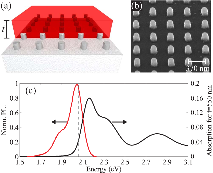
Figure 1(a) illustrates the sample. An aluminum nanoantenna array with a total size of mm2 was fabricated by substrate conformal imprint lithography Verschuuren (2010) and reactive ion etching of aluminium onto a fused silica substrate. Figure 1(b) shows an inclined view ( off the normal) scanning electron micrograph of the array. The nanoantennas are approximately disks with a diameter of nm and a height of nm, arranged in a square lattice with a constant nm. On top of the array we spin-coated a toluene solution with polystyrene and the organic dye Lumogen F305. Consequently, the toluene evaporated leaving a dye-doped polystyrene layer. The refractive index of this layer is higher than the underlying silica and overlying air, such that the array is embedded in a slab waveguide. We varied the thickness of this waveguide by controlling the spin-rate during the deposition and the viscosity of the solution. The latter was controlled through the polystyrene-to-toluene ratio, while the dye-to-polystyrene ratio (determining the final molecular concentration in the waveguide) was held constant at 3 weight . The influence of this molecular concentration on the optical properties of the waveguide was assessed through ellipsometry measurements, which yielded the complex refractive index of the dye-doped polymer. Over the entire visible spectrum, varied less than with respect to the index of a polystyrene layer without molecules. determines the absorptance of the waveguide, which we plot in Fig. 1(c) for nm as a black line. The absorptance is defined as where exp with the incident intensity, the intensity transmitted through the dye layer, and the free-space wavelength. At the energy of the dashed line in Fig. 1(c) (where the metallic nanoantennas and waveguide are tuned in resonance, as explained ahead), only of the incident light is absorbed by the molecules. This allows us to exclude the influence of the molecules on the nanoantenna-waveguide coupling at this energy. The photoluminescence spectrum of the waveguide is shown as a red line in Fig. 1(c).
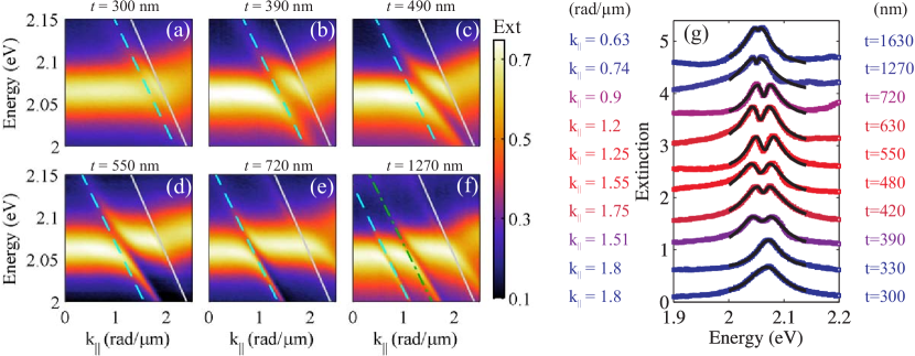
Figure 2 shows a series of extinction measurements of the same nanoantenna array embedded in waveguides of different thickness. The sample is illuminated by a collimated (angular spread ) TM-polarized white light beam from a halogen lamp, while a fiber-coupled spectrometer collects the transmitted light in the far-field. The extinction is defined as 1-, with the zeroth-order transmission through the array normalized to the transmission through the dye-doped polymer layer and substrate. We plot the extinction in color — same scale for all plots — as a function of the incident photon energy and in-plane momentum . A computer-controlled stage was used to rotate the sample by an angle , thereby changing the component of the wave vector parallel to the lattice vector, i.e., . is the magnitude of the free space wave vector and is a unit vector parallel to one of the two equivalent lattice vectors. We refer to the magnitude of as . The angular resolution of the measurements is . We focus on TM polarization because excellent spectral overlap between the coupled modes and the emission from the dye molecules aids to bring out the hybridization effects in both emission and extinction of TM-polarized light. However, strong coupling is not particular for one polarization, as confirmed for example by experiments with TE-polarized light Rodriguez et al. (2012b).
We now interpret the various features observed in the measurements in Fig. 2. For all , the broad extinction peak near 2.07 eV with a flat angular dispersion at small corresponds to the excitation of localized surface plasmon resonances (LSPRs). A plane wave that excites LSPRs can also be diffracted grazing to the surface of the array, leading to the so-called Rayleigh anomaly (RA) condition. The gray solid line overplotted on the measurements in Fig. 2 indicates the RA in glass, with a dispersion given by . Here, is the relevant order of diffraction, is the magnitude of the reciprocal lattice vector, and is the refractive index of the glass substrate. The periodic array may also enable the plane wave excitation of a guided mode in the polymer layer, which has a refractive index higher than its surroundings. The cyan dashed line, changing with , indicates the dispersion relation of fundamental TM0 guided mode calculated using the formalism described by Yariv and Yeh Yariv and Yeh (2007). We solve for the bound modes in a dielectric slab with refractive index (polystyrene), sandwiched between semi-infinite media with (air) and (glass). The thickness of the slab is obtained from profilometry measurements of the dye-doped polystyrene layer in experiments.
Figure 2 shows several dispersive features in extinction crossing or anti-crossing with the LSPR depending on . The feature near the RA condition remains as a small perturbation on the LSPR for all , and we therefore not dwell on it further. We focus on the feature near the LSPR-TM0-guided-mode crossing, which varies pronouncedly with . For nm, Fig. 2(a) shows a weak narrow feature crossing with the LSPR without significantly affecting it. This thin waveguide is close to cut-off, so the weakly confined TM0 guided mode dispersion follows closely the RA dispersion. As increases, the guided mode shifts away from the RA towards lower , and its signature in the spectra is clearly distinguished from the RA feature. In Fig. 2(b) we begin to see signatures of hybridization between the LSPR and TM0 guided mode. For increased [Figs. 2(c,d)], a mode splitting emerges near zero detuning, where the energies of the bare LSPR and TM0 guided mode cross but the coupled modes anti-cross. As transits across the zero detuning point, the coupled modes gradually exchange their resemblance to one or the other of the bare modes. This adiabatic mode exchange across the zero detuning point is, qualitatively speaking, the signature of strong coupling. The hybrid excitations emerging from the strong LSPR-guided mode coupling are known as waveguide-plasmon polaritons Christ et al. (2003); Rodriguez et al. (2012b). For nm [Fig. 2(e)], the energy splitting between the same two modes is reduced, and for nm [Fig. 2(f)] the splitting is much smaller than the linewidths (weak coupling). For , the higher order TM1 guided mode [green dash-dotted line in Fig. 2(f)] is also excited. However, we do not observe indications of strong coupling between the TM1 guided mode and the LSPR for any .
An interesting observation in the dispersion diagrams in Fig. 2 is that the calculated TM0 guided mode and the corresponding feature in extinction are in better agreement for thicker [Figs. 2(e,f)] than for the thinner [Figs. 2(a,b,c,d)] waveguides. We believe that this is due to the perturbation of the “bare” waveguide structure by the nanoantennas. For thinner waveguides a higher fraction of the dielectric slab is occupied by the nanoantennas. Therefore, the actual structure deviates more pronouncedly from the planar layer considered in the calculations. The most significant deviations between the calculated TM0 guided mode and the corresponding feature in extinction are observed for the structures displaying the strongest splittings [Figs. 2(c,d)], likely because in these cases the perturbative particle has a greater overlap with the guided mode eigenfield.
Next, we analyze in Fig. 2(g) the extinction measurements for various [more values than shown in Fig. 2(a)-(f)] at the value of corresponding to zero LSPR and TM0 guided mode detuning. This value of (shown on the left of each plot) was established on the basis of a non-linear least squares fit of a model system — coupled harmonic oscillators — to the data, as we explain next. In matrix form, the equations of motion of the model system are,
| (1) |
where we have assumed time-harmonic solutions. and are the eigenfrequencies of the LSPR and TM0 guided mode, and are their respective loss rates, while and are the oscillator displacements from equilibrium. represents the coupling strength between the two oscillators. On the right hand side of Eq. 1 appears the driving force per unit mass, , which represents the incident optical field with frequency . This force drives directly the LSPR only because in the absence of scatterers, the guided mode is not directly driven by a plane wave incident from the far-field. The guided mode is excited indirectly through the array. Our model assumes frequency-independent dissipative and coupling terms, which is valid for restricted energy ranges only. While relaxing these constraints could lead to a better quantitative agreement with the experiments, we show that a good fit and a reasonable description emerge in the spectral region of interest despite these simplifications.
To establish the zero-detuning values of we first let and be independent fit parameters. We fit the total power dissipated by both oscillators to the extinction spectra at the various values of . Zero-detuning is identified as the value of for which the difference between and is minimized. Having established this value, we then fit the model to the selected value of once more, but now with the strict equality . The black lines in Fig. 2(g) are these fits. The model spectra capture the behavior in our measurements well. From the fits, we retrieve the coupling and loss rates as a function of , and we plot these in Fig. 3. The error bars in energy represent a 2 () confidence interval on the fits. The error bars in are due to the uncertainty in the measurements of the waveguide thickness. The curves overplotted with the data points in Fig. 3 are guides to the eye.
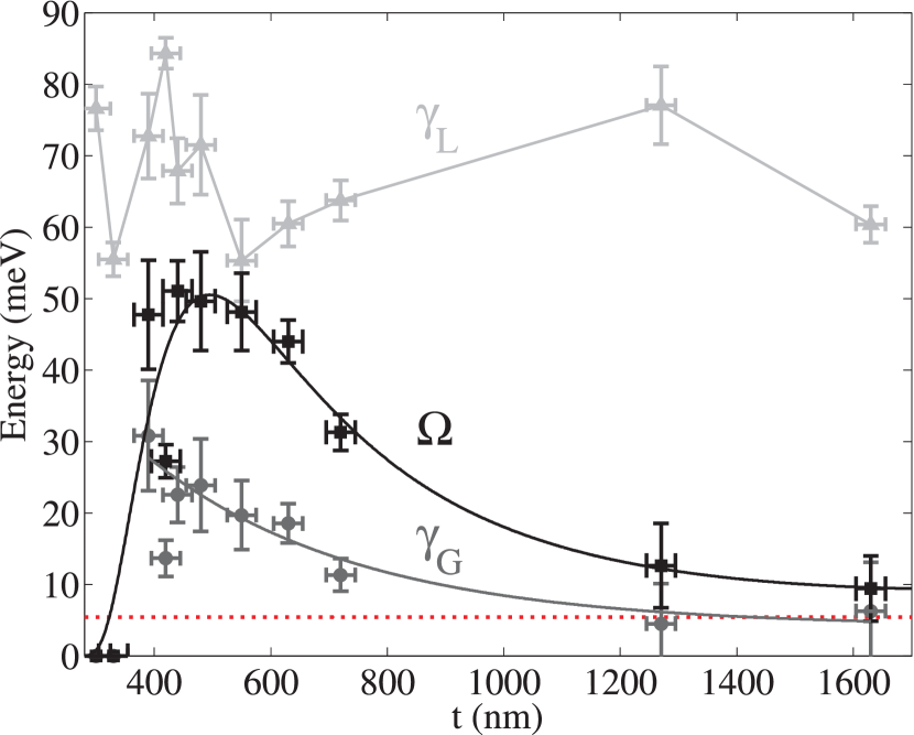
Figure 3 shows that the ratio of the coupling rate to the total loss rate is maximized at an optimum waveguide thickness nm. For this value, and (within the error bar). We interpret this condition as the onset of strong coupling. For thinner or thicker waveguides, is less than at least one of the loss rates (mostly ). This corresponds to the weak coupling regime, where energy dissipation is faster than energy exchange between the oscillators. The finding that this system transitions from weak to strong coupling for a limited range of waveguide thickness is a central result of this paper. We highlight that the system we investigate (periodic array of metallic nanoparticles coupled to a dielectric slab waveguide) has been actively studied for its ability to modify light propagation and emission in numerous ways Christ et al. (2003); Yannopapas et al. (2009); Zentgraf et al. (2009); Zhang et al. (2011); Bernal Arango et al. (2012); Rodriguez et al. (2012b). While several groups have presented evidence for strong or weak coupling between LSPRs and guided modes in various configurations, this is the first time that the same plasmonic system is shown to transition between the two regimes.
Intuitively, the transition from weak to strong coupling can be explained in view of how the waveguide thickness modifies the field overlap between the TM0 guided mode and the LSPR, which is localized near the base of the waveguide. In the thin waveguide limit, the guided mode is weakly confined and a significant fraction of its energy lies outside the slab. The coupling is therefore weak, because the field overlap with the nanoantennas is poor. In the thick waveguide limit, the fundamental guided mode is well confined. However, its electric field amplitude is greatest close to the center of the waveguide, far from the nanoantennas. Therefore, once again the coupling is weak because the field overlap with the nanoantennas is poor. An optimum coupling arises for an intermediate thickness, where the field overlap is greatest. In addition to this primary dependence of the coupling strength on the position of the nanoantennas, the coupling also depends on the shape of the nanoantennas. For example, we have observed (measurements not shown here) that an otherwise identical lattice of pyramidal rather than cylindrical nanoantennas displays weaker couplings with identical waveguides. The pyramidal nanoantennas lead to significantly different emission spectra. The differences are not only attributable to the well-known dependence of the bare LSPR energy and linewidth on the shape of the nanoantenna. We believe that also the coupling is shape-dependent because the positions of the electromagnetic hot-spots (where the field overlap with the guided mode is greatest) are shape-dependent. While an exhaustive study of shape-dependent couplings is beyond the scope of the present paper, we hereby point to this effect for consideration in future works.
We now comment on the dependence of the loss rates on . is affected by the local density of optical states at the position of the nanoantennas. As shown by Buchler and co-workers, LSPR radiative losses are affected by a nearby dielectric interface Buchler et al. (2005). Here, the proximity of the air-polystyrene interface to the nanoantennas (determined by ) leads to a modified LSPR linewidth. This is more clearly visible in the measurements for the thinnest waveguides [see Fig. 2(g)]. Besides this effect, we suspect that slightly different optical qualities (e.g. roughness) of the waveguides could also exert a small influence on our measurements. Regarding , its non-zero value could be considered surprising based on the fact that a bare guided mode in an unstructured dielectric slab is a bound mode, which implies zero decay rate. As we explain next, includes both radiation losses due to the structuring of the waveguide, and absorption losses due to the molecules in the waveguide. Radiation losses are enhanced for small because the actual dye-doped polystyrene waveguide — spatially modulated by the presence of the nanoantennas — deviates more pronouncedly from the flat layer supporting a strictly bound mode. Our data agrees with this intuition, since Fig. 3 shows that decreases as increases. At large , asymptotically approaches the absorption rate of the molecules in the waveguide ( meV), which is indicated by the red dotted line in Fig. 3. This absorption rate is derived from the complex refractive index of the dye-doped polystyrene layer, , which we obtained from ellipsometric measurements. Since the ratio gives the number of optical cycles after which the energy density of a wave decays, the absorption rate at frequency is . For the calculation in Fig. 3, we set , where the overbar indicates an average for all measured . The meV in the value quoted above represents slight variations of as a function of , which change the value of due to the frequency dispersion of the refractive index. It should be mentioned that a radiative contribution to implies, by reciprocity, the possibility of direct radiative excitation of this mode. Therefore, the assumption in our model (Eq. 1) that only the LSPR mode is driven directly by the harmonic force holds only approximately for small , and more faithfully for large .
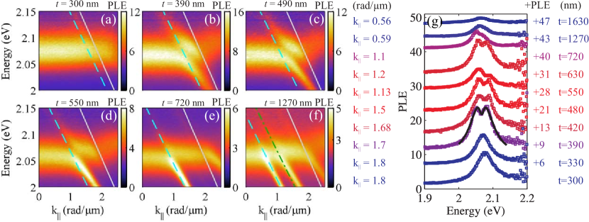
Next we present photoluminescence measurements corresponding to the same samples discussed in Fig. 2. The samples were pumped by a 2.8 eV continuous wave laser at a fixed angle of incidence 5∘. The variable angle emission was collected by a fiber-coupled spectrometer rotating in the far-field, with an angular resolution of . The pump irradiance ( mW/mm2) was far below the saturation threshold of the molecules. Figure 4 shows the photoluminescence enhancement (PLE) in color — varying scales — as a function of the emitted photon energy and . The PLE is defined as the ratio of the photoluminescence from the waveguide with and without the nanoantenna array.
The PLE displays an intricate dependence on that does not directly correlate with that of extinction. For nm [Fig. 4(a)], the PLE is dominated by the LSPR yielding a maximum 12-fold enhancement. For nm [Fig. 4(b)], the LSPR shows weak signatures of hybridization with the TM0 guided mode, while the maximum PLE increases to roughly 16-fold. For nm [Fig. 4(c)], the PLE from the weakly hybridized LSPR and TM0 guided mode are roughly equal, reaching a maximum 12-fold enhancement. For the three thickest waveguides [Figs. 4(d,e,f)] the LSPR enhancement is reduced and the PLE is dominated by the TM0 guided mode. Notice that for the 4 measurements with nm [Figs. 4(c,d,e,f)], the maximum PLE monotonically decreases. We attribute this reduction in PLE to a higher fraction of dye molecules that are effectively uncoupled from the nanoantenna array. For large , these are the molecules near the top of the waveguide, where the nanoantenna-enhanced near-fields have significantly decayed. Note that even though the molecules are uniformly distributed throughout the waveguide, the field overlap between the optical mode and the molecules is not constant in space. In particular, as increases beyond the characteristic decay length of the nanoantenna-enhanced near-fields (few hundred nm, depending on frequency and wave vector), the ensemble emission becomes increasingly dominated by molecules displaying a negligible field overlap with the LSPR, and little overlap with the guided mode.
We now focus on the relative strength of the PLE features and their connection to the properties of the coupled modes. We previously established, based on our analysis of the extinction spectra, that for the thinnest and thickest waveguides the system lies well into the weak coupling regime. In this case, the relevant eigenmodes are the LSPR and the TM0 guided mode — not their mixture. On either the small or large weak coupling regime, the extinction displays comparable LSPR lineshapes only marginally affected by the TM0 guided mode [Figs. 2(a,f)]. In contrast, the PLE differs remarkably in these two weak coupling regimes. For small the greatest contribution to the PLE comes from the LSPR [Fig. 4(a)], while for large it comes from the TM0 guided mode [Fig. 4(e,f)]. This is due to the different decay lengths of the modes, which leads to a greater field overlap with the emitters for the LSPR at small and for the TM0 guided mode at large . The extinction, on the other hand, is not affected by the field overlap of these modes with the emitters. Instead, the extinction is determined by the interference between incident and scattered fields. This leads to a spectral shift of the near-field with respect to the far-field Bryant et al. (2008); Ross and Lee (2009); Zuloaga and Nordlander (2011); Alonso-González et al. (2013), which can also explain the spectral shift of the emission enhancement with respect to the extinction in the presence of a single resonance Giannini et al. (2010). For coupled resonators, interference and electromagnetic retardation can lead to a more complex behavior, including a suppressed far-field response at the same frequency, wave vector, and polarization, for which the near-field is enhanced Hentschel et al. (2010); Frimmer et al. (2012); Rodriguez et al. (2013b). While such a condition is particularly attractive for enhancing light emission with reduced losses Rodriguez et al. (2012b), its relation to the weak-to-strong coupling transition has hitherto not been discussed. Here, by mapping this transition we demonstrate the different regimes in which waveguide-coupled light-emitting optical antennas can operate. On one hand, the results at small provide a design principle (optimum layer thickness) for generating angle-independent light emission enhancements. On the other hand, the results at large provide a design principle for generating directional narrowband light emission enhancements which follow the dispersion of guided modes. For intermediate , we observe that strong coupling induces a spectral window of far-field transparency accompanied by only a shallow dip in PLE at zero LSPR-guided mode detuning. Thus, in this region the near-field to far-field contrast is greatest.
We finalize the discussion of the PLE measurements by making a comparison with the measurements in Ref. Rodriguez et al. (2012b), where a nanoantenna array stands on rather than in a light-emitting waveguide. The greater field overlap between the optical modes enabled by the present configuration allows us to observe enhanced (but still weak) hybridization effects in PLE in the vicinity of the strong coupling regime ( nm nm). In contrast, no hybridization effects were observed in the PLE measurements of Ref. Rodriguez et al. (2012b). We stress the term “weak hybridization” because the dispersion and linewidths of the resonances are clearly modified [Fig. 4(b,c,d)], but their energy splitting at zero detuning never exceeds their linewidths. This is clear qualitatively, and also quantitatively, as revealed by fitting the PLE spectrum with the same model used for the extinction spectra (Eq. 1). The fit to the spectrum displaying the largest splitting [black line in Fig. 4(g)] yields meV, meV, and meV. We believe that the apparent contradiction in the values of the coupling and loss rates points to the highly interesting fact that any given system of coupled oscillators displays distinct observables with different lineshapes depending on how the oscillators are driven. Here, for example, a time-harmonic driving of only one mode as assumed in Eq. 1 seems inadequate to describe the PLE spectra. Recall that the PLE is generated by near-field rather than far-field excitation, and both modes can be directly excited. We also note that the maximum splitting in PLE occurs for nm rather than nm. The dependence of the apparent mode splitting on the observable quantity has been highlighted in Refs. Savona et al. (1995); Schwartz et al. (2011) in view of transmission, reflection, and absorption spectra. Here, we introduce a new quantity that needs consideration in emitting systems aimed to operate in the strong coupling regime: the PLE. While an unambiguous determination of the coupling strength is in principle only possible through an eigenmode analysis, experiments always retrieve observables in a driven system. It is therefore important to understand the dependence of these observables on the key parameters of the system (e.g., in our case). Furthermore, we point out that PLE and absorption measurements are not related through reciprocity. While Kirchoff’s Law relates absorption and emission at any point in space, an absorptance measurement of our sample largely probes the local field enhancements at the position of the nanoantennas, while PLE measurements probe the local field enhancements at the position of the molecules. As we show next, these two quantities can differ pronouncedly depending on the coupling strength and frequency detuning of the modes supported by the structure.
In what follows, we study the transition from weak to strong coupling between the LSPR and the TM0 guided mode using full wave simulations. Firstly, we confirm the features observed in experiments. Secondly, we interpret these features in terms of near-field maps. We have used two distinct methods bench-marked against each other. These are the Fourier modal method (S4) and the finite-element method (COMSOL). The Fourier modal method Li (1996a) is a plane wave expansion method to calculate the transmission, reflection and diffraction of layered biperiodic discontinuous structures, i.e. stratified gratings. We use the free implementation S4 of Liu and Fan Liu and Fan (2012). We find good convergence using just 289 plane waves provided we use parallellogramic truncation, and employ the proper factorization rules of Li Li (1996b) appropriate for high-index contrast crossed gratings. We take the same refractive index values used in the dispersion calculations (, , and ), and model the aluminum nanoantennas as cylinders of height 150 nm and diameter of 118 nm. The aluminum dielectric constant we use is a polynomial parametrization of measured ellipsometry data.
To model the PLE and visualize the near-fields, we use COMSOL rather than S4. The Fourier modal method is not optimized for high accuracy in fields according to a point-by-point local measure, while finite element simulations are optimal for real-space insight. As geometry we take the same parameters as in S4. The computational domain in COMSOL spans the unit cell in the periodicity plane, and extends several wavelengths perpendicularly into to the substrate and superstrate. We apply Bloch-Floquet boundary conditions at the edges of the unit cell and periodic port conditions for the remaining domain walls. The zero-order port on the air side is set for angled plane wave excitation. We have benchmarked the COMSOL simulations against S4 by comparing the calculated extinction for the nm structure. We find percent-level agreement for wave vectors below the RA in glass, i.e., in the range of the experiment. However, just beyond the RA in glass COMSOL shows fringes in extinction, which we attribute to spurious reflections off the periodic port boundary condition that occur when a diffracted order is grazing along the port in the substrate or superstrate. These artifacts could be reduced by extending above 7 wavelengths the computational domain in the direction perpendicular to the layers. However, this comes at the expense of an increased computational time compared to S4. Since we find excellent correspondence for extinction at all energy and momenta below the RA in glass, we conclude that the finite element simulation is fiducial for PLE and near-field maps in this spectral region.
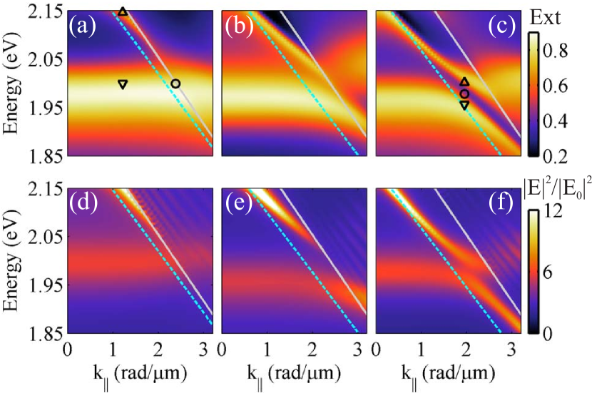
Figures 5(a,b,c) show the extinction (1-T0, for TM-polarized light, incident from air) simulated with S4 for three waveguide thicknesses: (a) nm, (b) nm, and (c) nm. The LSPR in the simulations is somewhat red-shifted with respect to the measurements. This is likely due to differences between the simulated and fabricated metallic structures in their dimensions or dielectric function. In addition, aluminum nanostructures present a 2-3 nanometers surface oxide (Al2O3) layer Knight et al. (2012), which is not taken into account in our simulations and could be the origin of small spectral shifts. Nevertheless, the simulations capture the essence of the measurements (Fig. 2) well, both displaying a transition from weak to strong coupling as increases. Notice in Fig. 5(c) that the avoided resonance crossing is centered at a larger value of than expected based on the calculated guided mode dispersion, in agreement with experiments [see Fig. 2(d)]. Figures 5(d,e,f) show the spectrally resolved electric field intensity enhancements for the same three waveguides, simulated with COMSOL. The enhancement is defined as , with and the total and incident electric field, respectively, both spatially averaged over the waveguide volume (excluding the volume of the particles). is related to the PLE by reciprocity, which states that the local electric field enhancement in the waveguide upon far-field plane wave illumination is equivalent to the plane wave strength in the far-field due to a localized source. Since our experiment averages all possible positions and orientations of the emitters in the entire waveguide, we integrate the total electric field intensity enhancement over the entire volume where the emitters are located. The resultant quantity can be regarded as the radiative part of the fractional (angle-resolved) local density of optical states. Comparing Fig. 5(d) with Fig. 4(a) shows that for nm, the dominant contribution to the field enhancement in the waveguide comes from the LSPR. This results in a broadband PLE feature with a flat angular dispersion. For nm, the and PLE spectra in Figs. 5 (f) and Fig. 4(d), respectively, display mixed features of the LSPR and guided mode with an anti-crossing between them. As in the measurements, the magnitude of the splitting at the avoided resonance crossing is smaller for PLE than for extinction [Figs. 2 (d) and Fig. 5(c)]. For intermediate values of , the and PLE spectra show characteristics in between these two cases. Overall, the simulated quantity qualitatively reproduces the PLE measurements. The agreement is better at lower than at higher energies because the absorption by the molecules (not taken into account in the simulations) limits the PLE at higher energies. Indeed, the imaginary component of the refractive index of the dye-doped polystyrene layer, , is roughly a factor of four higher at 2.15 eV than at 2.06 eV (the average eigenfrequency of the TM0 guided mode, , as obtained from the coupled harmonic oscillator fits). Hence, we expect re-absorption of the enhanced light emission to more seriously hamper the PLE at higher energies as the waveguide thickness increases. This expectation is in agreement with our measurements in Fig. 4, where the sharp feature in PLE associated with the guided mode gradually fades for energies above eV, and this effect becomes more pronounced as increases.
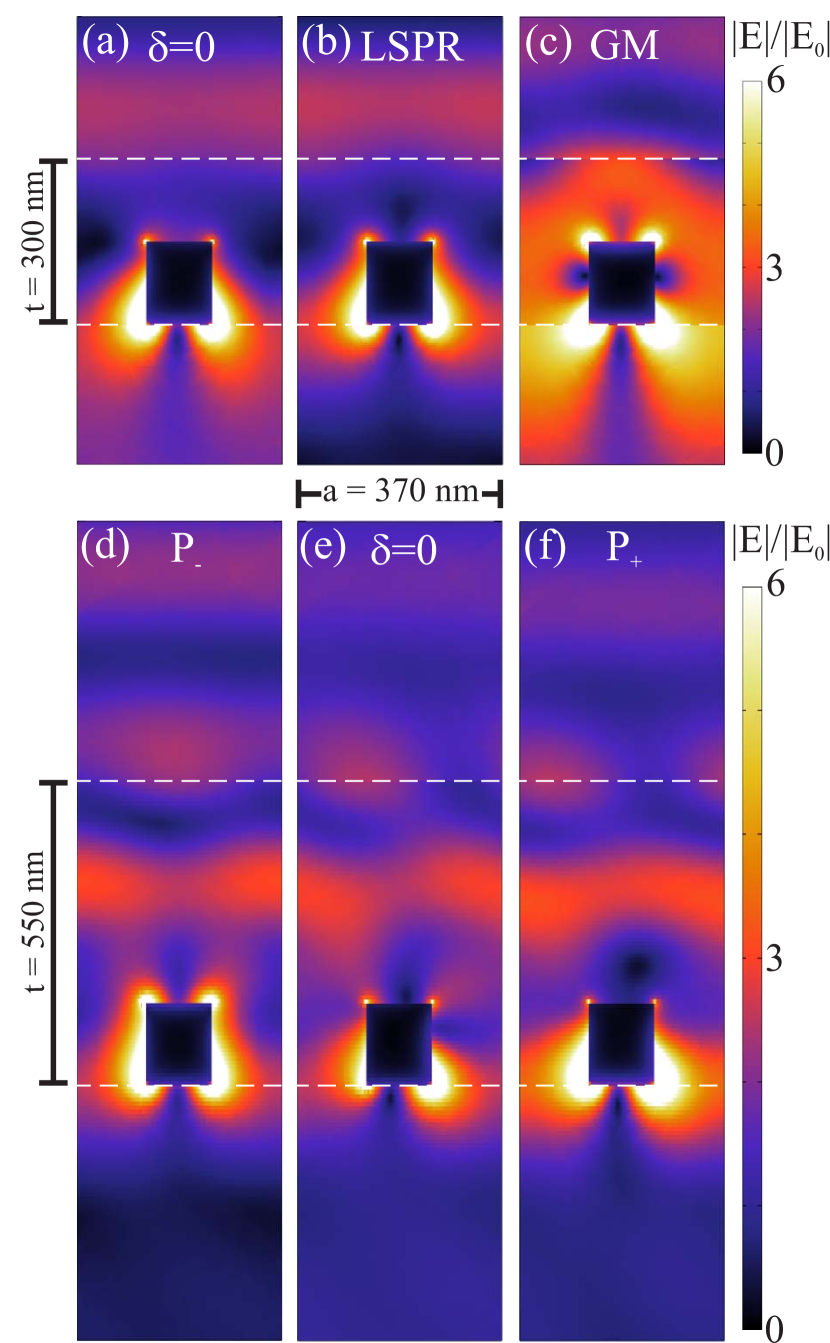
We now inspect the near-fields of the structure at selected energies and to illustrate the key differences between weak and strong coupling. In Fig. 6 we plot at a plane parallel to the incident electric field and intersecting the nanoantennas at their center. Figures 6(a,b,c) correspond to nm, while Figs. 6(d,e,f) correspond to nm. Figure 6(a) is close to zero detuning, as indicated by the open circle in Fig. 5(a). Figures 6(b,c) represent a large detuning, occurring at radm. In Fig. 6(b) the photon energy is 2 eV, as indicated by the downwards triangle in Fig. 5(a); this corresponds to the approximately bare LSPR. In Fig. 6(c) the photon energy is 2.147 eV, as indicated by the upwards triangle in Fig. 5(a); this corresponds to the approximately bare TM0 guided mode. The similarity of the fields in Fig. 6(a) and Fig. 6(b) is due to the weak coupling, which induces a negligible modification to the LSPR even at zero detuning with the guided mode. In contrast to both Figs. 6(a,b), the electric field enhancement in Fig. 6(c) is stronger and more delocalized. The weaker confinement of the field to the metal explains the narrower resonance linewidth at the conditions of Fig. 6(c).
Figures 6(d,e,f) illustrate the near-fields for three different energies all at radm, which is close to zero detuning for nm. Strong coupling leads to two new eigenstates, which we label as P- and P+ in Fig. 6(d) and Fig. 6(f), respectively. The energy and of P- and P+ are indicated by the downwards and upwards triangles in Fig. 5(c), respectively. The field profiles of P- and P+ are similar to each other because the strong coupling has hybridized the modes such that their individuality is lost. Here, waveguide-plasmon polaritons are a linear superposition of the bare LSPR and TM0 guided modes with equal weights. If the detuning parameter is varied from radm, the field solutions along the upper and lower polariton branches depart from this condition, gradually acquiring a resemblance to one or the other of the bare modes. Finally, an interesting situation occurs in Fig. 6(e), the energy and of which is indicated by the circle in Fig. 5(c). Here the local fields in the waveguide are still significantly enhanced but the extinction is reduced. This spectral region is particularly attractive for light-emitting plasmonic systems, as it enables simultaneously enhanced local fields at the position of the emitters (and therefore large fluorescence enhancements) and suppressed absorption losses in the metal.
In conclusion, we have investigated the light extinction and emission angular spectra of an aluminum nanoantenna array embedded in a luminescent slab waveguide. By varying the waveguide thickness we demonstrated the transition from weak to strong coupling between localized surface plasmons in the nanoantennas and the fundamental guided mode in the slab. Our results provide a design principle for hybrid dielectric-metallic resonators aimed at improving the performance of solid-state light-emitting devices, and shed new light on the near-field to far-field contrast of optical antenna arrays. In particular, we have shown how the same nanoantenna array can provide drastically different radiation patterns in photoluminescence enhancement as the coupling strength between the aforementioned two modes is varied. From a fundamental perspective, we envisage these results to stimulate a quest for a more comprehensive description of hybrid light-matter excitations in strongly coupled systems, as we have here shown that their observable properties (e.g. extinction and emission dispersion relations, and energy splitting of coupled modes) depend pronouncedly on the nature of the excitation source.
We thank Jorik van de Groep, Gabriel Lozano, and Erik Garnett for stimulating discussions. This work was supported by the Netherlands Foundation for Fundamental Research on Matter (FOM) and the Netherlands Organisation for Scientific Research (NWO), and is part of an industrial partnership program between Philips and FOM.
References
- Fano (1961) U. Fano, “Effects of Configuration Interaction on Intensities and Phase Shifts,” Phys. Rev. 124, 1866–1878 (1961).
- Boller et al. (1991) K.-J. Boller, A. Imamoglu, and S. E. Harris, “Observation of electromagnetically induced transparency,” Phys. Rev. Lett. 66, 2593–2596 (1991).
- Sarrazin et al. (2003) Michaël Sarrazin, Jean-Pol Vigneron, and Jean-Marie Vigoureux, “Role of Wood anomalies in optical properties of thin metallic films with a bidimensional array of subwavelength holes,” Phys. Rev. B 67, 085415 (2003).
- Genet et al. (2003) C. Genet, M.P. van Exter, and J.P. Woerdman, “Fano-type interpretation of red shifts and red tails in hole array transmission spectra,” Opt. Commun. 225, 331 – 336 (2003).
- Zhang et al. (2008) Shuang Zhang, Dentcho A. Genov, Yuan Wang, Ming Liu, and Xiang Zhang, “Plasmon Induced Transparency in Metamaterials,” Phys. Rev. Lett. 101, 047401 (2008).
- Liu et al. (2009) Na Liu, Lutz Langguth, Thomas Weiss, Jürgen Kästel, Michael Fleischhauer, Tilman Pfau, and Harald Giessen, “Plasmonic analogue of electromagnetically induced transparency at the Drude damping limit,” Nat. Mat. 8, 758–762 (2009).
- Tassin et al. (2009) P. Tassin, Lei Zhang, Th. Koschny, E. N. Economou, and C. M. Soukoulis, “Low-Loss Metamaterials Based on Classical Electromagnetically Induced Transparency,” Phys. Rev. Lett. 102, 053901 (2009).
- Mukherjee et al. (2010) Shaunak Mukherjee, Heidar Sobhani, J. Britt Lassiter, Rizia Bardhan, Peter Nordlander, and Naomi J. Halas, “Fanoshells: Nanoparticles with Built-in Fano Resonances,” Nano Lett. 10, 2694–2701 (2010).
- Kekatpure et al. (2010) Rohan D. Kekatpure, Edward S. Barnard, Wenshan Cai, and Mark L. Brongersma, “Phase-Coupled Plasmon-Induced Transparency,” Phys. Rev. Lett. 104, 243902 (2010).
- Miroshnichenko et al. (2010) Andrey E. Miroshnichenko, Sergej Flach, and Yuri S. Kivshar, “Fano resonances in nanoscale structures,” Rev. Mod. Phys. 82, 2257–2298 (2010).
- Luk’yanchuk et al. (2010) B. Luk’yanchuk, N. I. Zheludev, S. A. Maier, N. J. Halas, P. Nordlander, H. Giessen, and C. T. Chong, “The Fano resonance in plasmonic nanostructures and metamaterials,” Nat. Mat. 9, 707–715 (2010).
- Sheikholeslami et al. (2011) Sassan N. Sheikholeslami, Aitzol García-Etxarri, and Jennifer A. Dionne, “Controlling the Interplay of Electric and Magnetic Modes via Fano-like Plasmon Resonances,” Nano Lett. 11, 3927–3934 (2011).
- Alonso-Gonzalez et al. (2011) Pablo Alonso-Gonzalez, Martin Schnell, Paulo Sarriugarte, Heidar Sobhani, Chihhui Wu, Nihal Arju, Alexander Khanikaev, Federico Golmar, Pablo Albella, Libe Arzubiaga, Felix Casanova, Luis E. Hueso, Peter Nordlander, Gennady Shvets, and Rainer Hillenbrand, “Real-Space Mapping of Fano Interference in Plasmonic Metamolecules,” Nano Lett. 11, 3922–3926 (2011).
- Frimmer et al. (2012) Martin Frimmer, Toon Coenen, and A.F. Koenderink, “Signature of a fano resonance in a plasmonic metamolecule’s local density of optical states,” Phys. Rev. Lett. 108, 077404 (2012).
- Hao et al. (2008) Feng Hao, Yannick Sonnefraud, Pol Van Dorpe, Stefan A. Maier, Naomi J. Halas, and Peter Nordlander, “Symmetry Breaking in Plasmonic Nanocavities: Subradiant LSPR Sensing and a Tunable Fano Resonance,” Nano Lett. 8, 3983–3988 (2008).
- Neubrech et al. (2008) Frank Neubrech, Annemarie Pucci, Thomas Walter Cornelius, Shafqat Karim, Aitzol García-Etxarri, and Javier Aizpurua, “Resonant Plasmonic and Vibrational Coupling in a Tailored Nanoantenna for Infrared Detection,” Phys. Rev. Lett. 101, 157403 (2008).
- Offermans et al. (2011) Peter Offermans, Martijn C. Schaafsma, Said R. K. Rodriguez, Yichen Zhang, Mercedes Crego-Calama, Sywert H. Brongersma, and Jaime Gómez Rivas, “Universal Scaling of the Figure of Merit of Plasmonic Sensors,” ACS Nano 5, 5151–5157 (2011).
- Vecchi et al. (2009) G. Vecchi, V. Giannini, and J. Gómez Rivas, “Shaping the Fluorescent Emission by Lattice Resonances in Plasmonic Crystals of Nanoantennas,” Phys. Rev. Lett. 102, 146807 (2009).
- Rodriguez et al. (2012a) S. R. K. Rodriguez, G. Lozano, M. A. Verschuuren, R. Gomes, K. Lambert, B. De Geyter, A. Hassinen, D. Van Thourhout, Z. Hens, and J. Gómez Rivas, “Quantum rod emission coupled to plasmonic lattice resonances: A collective directional source of polarized light,” Appl. Phys. Lett. 100, 111103 (2012a).
- Rodriguez et al. (2012b) S. R. K. Rodriguez, S. Murai, M. A. Verschuuren, and J.G. Rivas, “Light-Emitting Waveguide-Plasmon Polaritons,” Phys. Rev. Lett. 109, 166803 (2012b).
- Lozano et al. (2013) Gabriel Lozano, Davy J Louwers, Said R.K. Rodriguez, Shunsuke Murai, Olaf TA Jansen, Marc A Verschuuren, and Jaime Gomez Rivas, “Plasmonics for solid-state lighting: enhanced excitation and directional emission of highly efficient light sources,” Light Sci. Appl. 2, e66 (2013).
- Bellessa et al. (2004) J. Bellessa, C. Bonnand, J. C. Plenet, and J. Mugnier, “Strong Coupling between Surface Plasmons and Excitons in an Organic Semiconductor,” Phys. Rev. Lett. 93, 036404 (2004).
- Dintinger et al. (2005) J. Dintinger, S. Klein, F. Bustos, W. L. Barnes, and T. W. Ebbesen, “Strong coupling between surface plasmon-polaritons and organic molecules in subwavelength hole arrays,” Phys. Rev. B 71, 035424 (2005).
- Vasa et al. (2008) P. Vasa, R. Pomraenke, S. Schwieger, Yu. I. Mazur, V. Kunets, P. Srinivasan, E. Johnson, J. E. Kihm, D. S. Kim, E. Runge, G. Salamo, and C. Lienau, “Coherent Exciton–Surface-Plasmon-Polariton Interaction in Hybrid Metal-Semiconductor Nanostructures,” Phys. Rev. Lett. 101, 116801 (2008).
- Manjavacas et al. (2011) A. Manjavacas, F.J. Garcia de Abajo, and P. Nordlander, “Quantum plexcitonics: Strongly interacting plasmons and excitons,” Nano Lett. 11, 2318–2323 (2011).
- Schwartz et al. (2011) T. Schwartz, J. A. Hutchison, C. Genet, and T. W. Ebbesen, “Reversible Switching of Ultrastrong Light-Molecule Coupling,” Phys. Rev. Lett. 106, 196405 (2011).
- González-Tudela et al. (2013) A. González-Tudela, P. A. Huidobro, L. Martín-Moreno, C. Tejedor, and F. J. García-Vidal, “Theory of Strong Coupling between Quantum Emitters and Propagating Surface Plasmons,” Phys. Rev. Lett. 110, 126801 (2013).
- Rodriguez et al. (2013a) S. R. K. Rodriguez, J. Feist, M. A. Verschuuren, F. J. Garcia Vidal, and J. Gómez Rivas, “Thermalization and cooling of plasmon-exciton polaritons: Towards quantum condensation,” Phys. Rev. Lett. 111, 166802 (2013a).
- Rodriguez and Rivas (2013) S.R.K. Rodriguez and J. Gómez Rivas, “Surface lattice resonances strongly coupled to rhodamine 6g excitons: tuning the plasmon-exciton-polariton mass and composition,” Opt. Express 21, 27411–27421 (2013).
- Väkeväinen et al. (2014) A. I. Väkeväinen, R. J. Moerland, H. T. Rekola, A.-P. Eskelinen, J.-P. Martikainen, D.-H. Kim, and P. Törmä, “Plasmonic surface lattice resonances at the strong coupling regime,” Nano Lett. 14, 1721–1727 (2014).
- Hutchison et al. (2012) James A. Hutchison, Tal Schwartz, Cyriaque Genet, Eloïse Devaux, and Thomas W. Ebbesen, “Modifying Chemical Landscapes by Coupling to Vacuum Fields,” Angew. Chem. Int. Ed. 51, 1592–1596 (2012).
- Hutchison et al. (2013) James A. Hutchison, Andrea Liscio, Tal Schwartz, Antoine Canaguier-Durand, Cyriaque Genet, Vincenzo Palermo, Paolo Samorì, and Thomas W. Ebbesen, “Tuning the Work-Function Via Strong Coupling,” Adv. Mater. 25, 2481–2485 (2013).
- Bharadwaj et al. (2009) Palash Bharadwaj, Bradley Deutsch, and Lukas Novotny, “Optical antennas,” Adv. Opt. Photon. 1, 438–483 (2009).
- Christ et al. (2003) A. Christ, S. G. Tikhodeev, N. A. Gippius, J. Kuhl, and H. Giessen, “Waveguide-Plasmon Polaritons: Strong Coupling of Photonic and Electronic Resonances in a Metallic Photonic Crystal Slab,” Phys. Rev. Lett. 91, 183901 (2003).
- Zentgraf et al. (2009) Thomas Zentgraf, Shuang Zhang, Rupert F. Oulton, and Xiang Zhang, “Ultranarrow coupling-induced transparency bands in hybrid plasmonic systems,” Phys. Rev. B 80, 195415 (2009).
- Yannopapas et al. (2009) Vassilios Yannopapas, Emmanuel Paspalakis, and Nikolay V. Vitanov, “Electromagnetically induced transparency and slow light in an array of metallic nanoparticles,” Phys. Rev. B 80, 035104 (2009).
- Février et al. (2012) Mickaël Février, Philippe Gogol, Abdelhanin Aassime, Robert Mégy, Cécile Delacour, Alexei Chelnokov, Aniello Apuzzo, Sylvain Blaize, Jean-Michel Lourtioz, and Béatrice Dagens, “Giant coupling effect between metal nanoparticle chain and optical waveguide,” Nano Lett. 12, 1032–1037 (2012).
- Bernal Arango et al. (2012) Felipe Bernal Arango, Andrej Kwadrin, and A. Femius Koenderink, “Plasmonic Antennas Hybridized with Dielectric Waveguides,” ACS Nano 6, 10156–10167 (2012).
- Verschuuren (2010) Marc A. Verschuuren, Substrate Conformal Imprint Lithography for Nanophotonics, PhD dissertation, Utrecht University (2010).
- Yariv and Yeh (2007) Amnon Yariv and Pochi Yeh, Photonics: Optical Electronics in Modern Communications, 6th ed. (Oxford University Press, Oxford, 2007).
- Zhang et al. (2011) Jing Zhang, Wenli Bai, Likang Cai, Yun Xu, Guofeng Song, and Qiaoqiang Gan, “Observation of ultra-narrow band plasmon induced transparency based on large-area hybrid plasmon-waveguide systems,” Appl. Phys. Lett. 99, 181120 (2011).
- Buchler et al. (2005) B. C. Buchler, T. Kalkbrenner, C. Hettich, and V. Sandoghdar, “Measuring the Quantum Efficiency of the Optical Emission of Single Radiating Dipoles Using a Scanning Mirror,” Phys. Rev. Lett. 95, 063003 (2005).
- Bryant et al. (2008) Garnett W. Bryant, F. Javier García de Abajo, and Javier Aizpurua, “Mapping the Plasmon Resonances of Metallic Nanoantennas,” Nano Lett. 8, 631–636 (2008).
- Ross and Lee (2009) Benjamin M. Ross and Luke P. Lee, “Comparison of near- and far-field measures for plasmon resonance of metallic nanoparticles,” Opt. Lett. 34, 896–898 (2009).
- Zuloaga and Nordlander (2011) Jorge Zuloaga and Peter Nordlander, “On the Energy Shift between Near-Field and Far-Field Peak Intensities in Localized Plasmon Systems,” Nano Lett. 11, 1280–1283 (2011).
- Alonso-González et al. (2013) P. Alonso-González, P. Albella, F. Neubrech, C. Huck, J. Chen, F. Golmar, F. Casanova, L. E. Hueso, A. Pucci, J. Aizpurua, and R. Hillenbrand, “Experimental Verification of the Spectral Shift between Near- and Far-Field Peak Intensities of Plasmonic Infrared Nanoantennas,” Phys. Rev. Lett. 110, 203902 (2013).
- Giannini et al. (2010) V. Giannini, G. Vecchi, and J. Gómez Rivas, “Lighting Up Multipolar Surface Plasmon Polaritons by Collective Resonances in Arrays of Nanoantennas,” Phys. Rev. Lett. 105, 266801 (2010).
- Hentschel et al. (2010) Mario Hentschel, Michael Saliba, Ralf Vogelgesang, Harald Giessen, A. Paul Alivisatos, and Na Liu, “Transition from isolated to collective modes in plasmonic oligomers,” Nano Lett. 10, 2721–2726 (2010).
- Rodriguez et al. (2013b) S. R. K. Rodriguez, O. T. A. Janssen, G. Lozano, A. Omari, Z. Hens, and J. Gómez Rivas, “Near-field resonance at far-field-induced transparency in diffractive arrays of plasmonic nanorods,” Opt. Lett. 38, 1238–1240 (2013b).
- Savona et al. (1995) V. Savona, L.C. Andreani, P. Schwendimann, and A. Quattropani, “Quantum well excitons in semiconductor microcavities: Unified treatment of weak and strong coupling regimes,” Solid State Commun. 93, 733 – 739 (1995).
- Li (1996a) Lifeng Li, “Formulation and comparison of two recursive matrix algorithms for modeling layered diffraction gratings,” J. Opt. Soc. Am. A 13, 1024 (1996a).
- Liu and Fan (2012) Victor Liu and Shanhui Fan, “S4 : A free electromagnetic solver for layered periodic structures,” Comput. Phys. Commun. 183, 2233 – 2244 (2012).
- Li (1996b) Lifeng Li, “Use of Fourier series in the analysis of discontinuous periodic structures,” J. Opt. Soc. Am. A 13, 1870–1876 (1996b).
- Knight et al. (2012) Mark W. Knight, Lifei Liu, Yumin Wang, Lisa Brown, Shaunak Mukherjee, Nicholas S. King, Henry O. Everitt, Peter Nordlander, and Naomi J. Halas, “Aluminum plasmonic nanoantennas,” Nano Lett. 12, 6000–6004 (2012).