Quantitative Temperature Dependence of Longitudinal Spin Seebeck Effect
at High Temperatures
Abstract
This article reports temperature-dependent measurements of longitudinal spin Seebeck effects (LSSEs) in Pt/Y3Fe5O12 (YIG)/Pt systems in a high temperature range from room temperature to above the Curie temperature of YIG. The experimental results show that the magnitude of the LSSE voltage in the Pt/YIG/Pt systems rapidly decreases with increasing the temperature and disappears above the Curie temperature. The critical exponent of the LSSE voltage in the Pt/YIG/Pt systems at the Curie temperature was estimated to be 3, which is much greater than that for the magnetization curve of YIG. This difference highlights the fact that the mechanism of the LSSE cannot be explained in terms of simple static magnetic properties in YIG.
pacs:
85.75.-d, 72.25.-b, 72.15.Jf, 73.50.LwI I. INTRODUCTION
The Seebeck effect converts a temperature difference into electric voltage in conductors Seebeck1 . Since the discovery of the Seebeck effect nearly 200 years ago, it has been studied intensively to realize simple and environmentally-friendly energy-conversion technologies SeebeckApplication . The Seebeck effect has been measured using various materials in a wide temperature range to investigate thermoelectric conversion performance and thermoelectric transport properties. Temperature-dependent measurements in a high temperature range are especially important in the investigation of the Seebeck effect, since thermoelectric devices are often used above room temperature SeebeckHighT1 ; SeebeckHighT2 .
In the field of spintronics spintronics1 ; spintronics2 ; spintronics3 , a spin counterpart of the Seebeck effect —the spin Seebeck effect (SSE)— was recently discovered. The SSE converts a temperature difference into spin voltage in ferromagnetic or ferrimagnetic materials. When a conductor is attached to a magnet under a temperature gradient, the thermally generated spin voltage in the magnet injects a spin current spincurrent1 ; spincurrent2 ; spincurrent3 into the conductor. Since the SSE occurs not only in metals SSE1 ; SSE10 ; SSE19 ; SSE27 and semiconductors SSE4 ; SSE9 but also in insulators SSE3 ; SSE5 ; SSE12 ; SSE13 ; SSE16 ; SSE17 ; SSE18 ; SSE19 ; SSE21 ; SSE24 ; SSE25 ; SSE26 ; SSE_Rezende ; SSE_time_resolved1 ; SSE_time_resolved2 ; SSEJAPfull ; SSE-JPCM , it enables the construction of “insulator-based thermoelectric generators” SSE13 in combination with the inverse spin Hall effect (ISHE) ISHE1 ; ISHE2 ; ISHE3 ; ISHE4 ; ISHE5 , which was impossible if only the conventional Seebeck effect was used.
The observation of the SSE in insulators has been reported mainly in a longitudinal configuration SSE5 ; SSE12 ; SSEJAPfull ; SSE13 ; SSE16 ; SSE17 ; SSE18 ; SSE19 ; SSE21 ; SSE24 ; SSE25 ; SSE26 ; SSE_Rezende ; SSE_time_resolved1 ; SSE_time_resolved2 ; SSE-JPCM . The sample system for measuring the longitudinal SSE (LSSE) is a simple paramagnetic metal (PM)/ferrimagnetic insulator (FI) junction system. In many cases, Pt and Y3Fe5O12 (YIG) are used as PM and FI, respectively. When a temperature gradient is applied to the PM/FI system perpendicular to the interface, the spin voltage is thermally generated and injects a spin current into the PM along the direction owing to thermal spin-pumping mechanism SSE2 ; SSE6 ; SSE7 ; SSE8 ; SSE14 ; SSE15 ; SSE20 ; LSSE_Adachi ; SSE23 . This thermally induced spin current is converted into an electric field by the ISHE in the PM according to the relation
| (1) |
where is the spatial direction of the thermally induced spin current and is the spin-polarization vector of electrons in the PM, which is parallel to the magnetization of FI [see Fig. 1(a)]. By measuring in the PM, one can detect the LSSE electrically.
In the experimental research on the SSE, temperature-dependent measurements also have been used for investigating various thermo-spin transport properties, such as phonon-mediated effects SSE4 ; SSE9 ; SSE6 ; SSE11 , correlation between the SSE and magnon excitation SSE_Rezende ; Boona , and effects of metal-insulator phase transition SSE19 . However, all the experiments on the SSE to date have been performed around and below room temperature. In this article, we report quantitative temperature-dependent measurements of the LSSE in Pt/YIG systems in the high temperature range from room temperature to above the Curie temperature of YIG.
II II. EXPERIMENTAL PROCEDURE
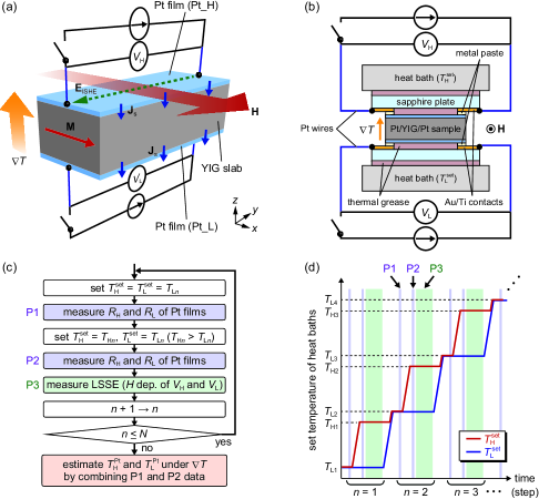
The sample system used in this study consists of a single-crystalline YIG slab covered with Pt films. One difference from conventional samples is that the Pt films are put on both the top and bottom surfaces of the YIG slab [Fig. 1(a)], while only the top surface of YIG is covered with a Pt film in conventional samples SSE5 ; SSE17 ; SSE25 ; SSE-JPCM . The lengths of the YIG slab along the , , and directions are 3 mm, 7 mm, and 1 mm, respectively. 10-nm-thick Pt films were sputtered on the whole of the -mm2 (111) surfaces of the YIG. The top and bottom Pt films are electrically insulated from each other because YIG is a very good insulator. Since YIG has the large charge gap of 2.7 eV Kajiwara_nature , thermal excitation of charge carriers in YIG is vanishingly small even at the high temperatures.
To attach electrodes to both the Pt films symmetrically and to generate a uniform temperature gradient, we made the configuration shown in Fig. 1(b). Here, the Pt/YIG/Pt sample was sandwiched between two 0.5-mm-thick sapphire plates of which the surface is covered with two separated Au/Ti contacts. The distance between the two Au/Ti contacts is . To extract voltage signals in the Pt films, both the ends of the Pt films are connected to the Au/Ti contacts via sintering metal paste, which can be used up to 900 ∘C, and thin Pt wires with the diameter of 0.1 mm were attached to the end of the contacts [see Fig. 1(b)]. The sapphire plates are thermally connected to heat baths of which the temperatures are controlled with the accuracy of by using PID (proportional-integral-derivative) temperature controllers. We attached thermal paste to both the surfaces of the sapphire plates, except for the regions of the Au/Ti contacts, to improve the thermal contact [see Fig. 1(b)]. During the measurements of the LSSE, the temperature of the upper heat bath, , is set to be higher than that of the lower one, . According to the direction of the temperature gradient, hereafter, the top and bottom Pt films of the Pt/YIG/Pt sample are referred to as ‘PtH’ and ‘PtL’, respectively. In this setup, we can measure the electric voltage () and resistance () between the ends of PtH (PtL) without changing electrodes, wiring, and measurement equipment [see also the caption of Fig. 1]. An external magnetic field (with the magnitude ) was applied along the direction.
To investigate the temperature dependence of the LSSE quantitatively, it is important to estimate the temperature difference between the top and bottom of the YIG sample. However, in the conventional experiments, the temperatures of the heat baths, not the sample itself, were usually monitored SSEJAPfull . Therefore, the measured temperature difference includes the contributions from the interfacial thermal resistance between the sample and heat baths and from small temperature gradients in the sample holders. To avoid this problem, in this study, we used the Pt films not only as spin-current detectors but also as temperature sensors SSE26 ; SSE_time_resolved2 ; we can know the temperatures of the Pt films from the temperature dependence of the resistance of the films, enabling the estimation of the temperature difference between the top and bottom of the sample during the LSSE measurements.
| Step number | (K) | (K) |
|---|---|---|
| 1 | 290 | 298 |
| 2 | 300 | 308 |
| 3 | 310 | 318 |
| 4 | 320 | 328 |
| 5 | 330 | 338 |
| 31 | 590 | 598 |
| 32 | 600 | 608 |
| 33 | 610 | 618 |
| 34 () | 620 | 628 |
Figure 1(c) shows the flow chart of the measurement processes. The measurement comprises the following three processes P1-P3, and the processes are repeated times. Hereafter, and denote the set temperatures for each measurement step number (see Table 1, where the values of and for each are shown). The process P1 is the measurement of the resistance of PtH and PtL, and , in the isothermal condition, where the temperatures of the heat baths are set to the same temperature: . In this isothermal condition, the temperature of the Pt/YIG/Pt sample is uniform and very close to the set temperature of the heat baths irrespective of the presence of the interfacial thermal resistance. Next, we apply a temperature gradient to the Pt/YIG/Pt sample by increasing the temperature of the upper heat bath, where and with (see Table 1). After waiting until the temperatures are stabilized, we measure the resistance of the Pt films under the temperature gradient: this is the process P2. The processes P1 and P2 are performed without applying . Immediately after the process P2, we proceed to the process P3; the LSSE, i.e. the dependence of and , is measured with keeping the magnitude of constant. After finishing the LSSE measurements, we go on to the next step and increase by 1, where the values of and are increased as shown in Table 1. These measurement processes are summarized in Fig. 1(d).
The calibration method of the sample temperatures is as follows. From the process P1, we obtain the temperature () dependence of and under the isothermal condition. By comparing the resistance under the temperature gradient, obtained from the process P2, with the isothermal - curves, we can calibrate the temperature of the Pt films, and , under the temperature gradient, allowing us to estimate the average temperature () and the temperature difference () in the YIG slab during the LSSE measurements. The and values are free from the contributions from the interfacial thermal resistance between the sample and heat baths and from the temperature gradients in the sapphire plates, enabling the quantitative evaluation of the LSSE at various temperatures. Although the experimental protocol proposed here cannot estimate the contributions of the interfacial thermal resistance at the Pt/YIG interfaces and temperature gradients in the Pt films, they are negligible compared with the temperature difference applied to the YIG slab SSE24 ; SSE-JPCM .
III III. RESULTS AND DISCUSSION
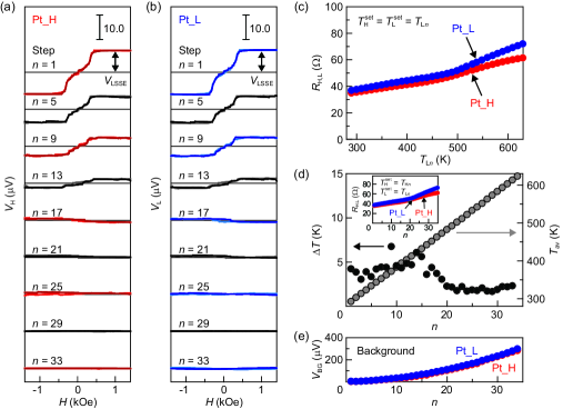
Figures 2(a) and 2(b) respectively show the dependence of and in the Pt/YIG/Pt sample for each step number , measured when . Around room temperature, we observed clear voltage signals in both the Pt films; the signs of and are reversed in response to the reversal of the magnetization direction of the YIG slab. Since the contribution of anomalous Nernst effects induced by proximity ferromagnetism in Pt Proximity is negligibly small in Pt/YIG systems, the voltage signals observed here are due purely to the LSSE SSE17 ; SSE25 ; SSE-JPCM . The sign of the LSSE voltage in PtH was observed to be the same as that in PtL, a situation consistent with the scenario of the SSE SSE2 ; SSE7 ; SSE20 ; comment_sign . Here we note that, although the large background voltage appears due to unavoidable thermopower differences in the wires with increasing [Fig. 2(e)], the noise level in the and signals does not increase and the drift of is small [Figs. 2(a) and 2(b)]. Therefore, we can extract the LSSE voltage simply by measuring the dependence of and . We also found that the magnitude of the LSSE voltage in the Pt/YIG/Pt sample monotonically decreases with increasing the temperature.
To quantitatively discuss the temperature dependence of the LSSE voltage in the Pt/YIG/Pt sample, we estimate and at each step number by using the method explained in Sec. II. Figure 2(c) shows the dependence of and for the Pt films measured under the isothermal condition. By combining the isothermal - curves with the and data under the temperature gradient [the inset to Fig. 2(d)], we obtain the and values at each [Fig. 2(d)]. Importantly, the calibrated values of are dependent on and always smaller than the temperature difference applied to the heat baths due to the interfacial thermal resistance and temperature gradients in the sapphire plates (note that for all the measurements as shown in Table 1).
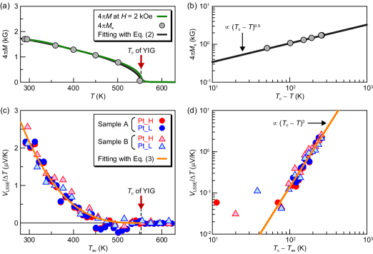
Figure 3(c) shows the LSSE voltage normalized by the calibrated temperature difference applied to the Pt/YIG/Pt sample, , as a function of . Here, denotes () for PtH (PtL) at . We confirm again that the magnitude of monotonically decreases with increasing the temperature and disappears above the Curie temperature of YIG, where of our YIG slab was experimentally estimated to be 553 K (see Appendix A). This behavior was observed not only in one sample but also in our different samples as exemplified in Fig. 3(c). Interestingly, the temperature dependence of is significantly different from the magnetization () curve of the YIG slab [compare Figs. 3(a) and 3(c)]; the magnitude of rapidly decreases with a concave-up shape, while the magnetization curve of YIG exhibits a standard concave-down shape. We also checked that the strong temperature dependence of the LSSE voltage in the Pt/YIG/Pt sample cannot be explained by the weak temperature dependence of the thermal conductivity of YIG (see Appendix B). Similar difference in the temperature-dependent data between the ISHE voltage and magnetization was observed also in Pt/GaMnAs systems in the measurement of the transverse SSEs SSE4 ; SSE9 .
The behavior of physical quantities near continuous phase transitions can be described by critical exponents in general. Here, we compare the critical exponents for the observed temperature dependences of the LSSE voltage in the Pt/YIG/Pt sample and the magnetization of YIG. First, we checked that the magnetization curve of YIG is well reproduced by a standard mean-field model Chikazumi :
| (2) |
where the critical exponent is fixed at 0.5 and is an adjustable parameter [see Figs. 3(a) and 3(b)]. The critical exponent for the LSSE was estimated by fitting the experimental data in Fig. 3(c) with the following equation:
| (3) |
where both and are adjustable parameters and is regarded as for the LSSE data. We found that the observed temperature dependence of for the Pt/YIG/Pt sample is well fitted by Eq. (3) with , which is much greater than the critical exponent for the magnetization curve [see also the double logarithmic plot in Fig. 3(d)]. This big difference in the critical exponents between the LSSE and magnetization emphasizes the fact that the LSSE is not attributed solely to static magnetic properties in YIG.
Here, we qualitatively discuss the origin of the temperature dependence of the LSSE voltage in the Pt/YIG/Pt sample. According to the thermal spin-pumping mechanism SSE2 ; SSE20 and phenomenological calculation of the ISHE combined with short-circuit effects NakayamaPRB , the magnitude of the LSSE voltage is determined mainly by the following factors: the spin-mixing conductance Tserkovnyak05 ; Jia11a ; Weiler13 ; Qiu13 at the Pt/YIG interfaces, spin-diffusion length and spin-Hall angle of Pt, and difference between an effective magnon temperature in YIG and an effective electron temperature in Pt. Since the LSSE voltage is proportional to the spin-mixing conductance SSE2 , it can contribute directly to the observed temperature dependence of the LSSE voltage. Recently, Ohnuma et al. formulated the relation between the spin-mixing conductance and interface - interaction at paramagnet/ferromagnet interfaces, and predicted that the spin-mixing conductance is proportional to of the ferromagnet Ohnuma2014 . By combining this prediction with Eq. (2), the spin-mixing conductance is proportional to , of which the critical exponent () is greater than that for the magnetization curve. Although the temperature dependence of the spin-mixing conductance can explain the facts that the LSSE voltage monotonically decreases with increasing the temperature and disappears at , it is still much weaker than the observed dependence of the LSSE voltage. Furthermore, if the spin-diffusion length of Pt decreases with increasing the temperature Marmion2014PRB , it can also contribute to reducing the LSSE voltage at high temperatures, while the spin-Hall angle of Pt was shown to exhibit weak temperature dependence Vila2007 (note that the magnitude of the ISHE voltage monotonically decreases with decreasing the spin-diffusion length when the spin-Hall angle is constant NakayamaPRB ). The effective magnon-electron temperature difference could also be an important factor, but there is no clear framework to determine its temperature dependence at the present stage. Therefore, more elaborate investigations are necessary for the complete understanding of the temperature dependence of the LSSE voltage.
IV IV. CONCLUSION
In this study, we reported the longitudinal spin Seebeck effects (LSSEs) in Y3Fe5O12 (YIG) slabs sandwiched by two Pt films in the high temperature range from room temperature to above the Curie temperature of YIG. To investigate the temperature dependence of the LSSE quantitatively, we used the Pt films not only as spin-current detectors but also as temperature sensors. The measurement processes used here enabled accurate estimation of the average temperature and temperature difference of the sample, being free from thermal artifacts. We found that the magnitude of the LSSE in the Pt/YIG/Pt sample rapidly decreases with increasing the temperature and disappears above of YIG; the observed LSSE voltage exhibits the dependence of which the critical exponent () is much greater than that of the magnetization of YIG (). Although more detailed experimental and theoretical investigations are required to clarify the microscopic origin of this discrepancy, we anticipate that the quantitative temperature-dependent LSSE data at high temperatures will be helpful for obtaining full understanding of the mechanism of the LSSE.
ACKNOWLEDGMENTS
The authors thank S. Maekawa, H. Adachi, Y. Ohnuma, N. Yokoi, K. Sato, and J. Ohe for valuable discussions and Y. Zhang for his assistance in magnetometry measurements. This work was supported by PRESTO-JST “Phase Interfaces for Highly Efficient Energy Utilization”, CREST-JST “Creation of Nanosystems with Novel Functions through Process Integration”, Grant-in-Aid for Young Scientists (A) (25707029), Grant-in-Aid for Challenging Exploratory Research (26600067), Grant-in-Aid for Scientific Research (A) (24244051) from MEXT, Japan, LC-IMR of Tohoku University, the Sumitomo Foundation, the Tanikawa Fund Promotion of Thermal Technology, the Casio Science Promotion Foundation, and the Iwatani Naoji Foundation.
APPENDIX A: ESTIMATION OF CURIE TEMPERATURE OF YIG
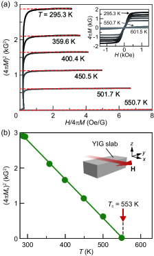
The Curie temperature of the YIG slab used in the present study was estimated from vibrating sample magnetometry and Arrott-plot analysis Chikazumi ; Arrott . The inset to Fig. 4(a) shows the dependence of the magnetization of the YIG slab for various values of . From this result, we obtained the Arrott plots, i.e. dependence of , of the YIG slab [see Fig. 4(a)]. The saturation magnetization of the YIG at each temperature was extracted by extrapolating the data in the high-magnetic-field range to zero field [see red dotted lines in Fig. 4(a)]. As shown in Fig. 4(b), the dependence of of the YIG slab is well fitted by a linear function; the horizontal intercept of the linear fit line corresponds to . The fitting result shows that the Curie temperature of our YIG slab is , which is consistent with literature values YIG1 ; YIG2 .
APPENDIX B: TEMPERATURE DEPENDENCE OF THERMAL CONDUCTIVITY OF YIG
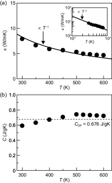
Figure 5(a) shows the thermal conductivity of the YIG slab used in the present study as a function of . The values were obtained by the combination of thermal diffusivity measured by a laser-flash method and specific heat measured by a differential scanning calorimetry. Here, we measured the thermal diffusivity along the [111] direction of the single-crystalline YIG slab, which is parallel to the direction in the LSSE setup. As shown in Fig. 5(b), the measured values are consistent with the Dulong-Petit (DP) law Seebeck1 ; the difference of the values from the DP specific heat of YIG, , is less than 10 % of for . The observed dependence of is well fitted by , indicating that the thermal conductivity of the YIG is dominated by phonons in this temperature range [see also the inset to Fig. 5(a)]. The value at 300 K is consistent with literature values YIG_kappa1 ; YIG_kappa2 ; YIG_kappa3 . We also confirmed that the dependence of is much weaker than that of the LSSE voltage in the Pt/YIG/Pt sample [compare Figs. 3(c) and 5(a)] and shows no anomaly around .
References
- (1) N. W. Ashcroft and N. D. Mermin, Solid State Physics (Saunders College, Philadelphia, 1976).
- (2) S. B. Riffat and X. Ma, Thermoelectrics: a Review of Present and Potential Applications, Appl. Therm. Eng. 23, 913 (2003).
- (3) J. P. Heremans, V. Jovovic, E. S. Toberer, A. Saramat, K. Kurosaki, A. Charoenphakdee, S. Yamanaka, and G. J. Snyder, Enhancement of Thermoelectric Efficiency in PbTe by Distortion of the Electronic Density of States, Science 321, 554 (2008).
- (4) L.-D. Zhao, S.-H. Lo, Y. Zhang, H. Sun, G. Tan, C. Uher, C. Wolverton, V. P. Dravid, and M. G. Kanatzidis, Ultralow Thermal Conductivity and High Thermoelectric Figure of Merit in SnSe Crystals, Nature 508, 373 (2014).
- (5) S. A. Wolf, D. D. Awschalom, R. A. Buhrman, J. M. Daughton, S. von Molnar, M. L. Roukes, A. Y. Chtchelkanova, and D. M. Treger, Spintronics: A Spin-Based Electronics Vision for the Future, Science 294, 1488 (2001).
- (6) I. Žutić, J. Fabian, and S. Das Sarma, Spintronics: Fundamentals and Applications, Rev. Mod. Phys. 76, 323 (2004).
- (7) S. Maekawa, ed., Concepts in Spin Electronics (Oxford University Press, Oxford, 2006).
- (8) J. C. Slonczewski, Current-Driven Excitation of Magnetic Multilayers, J. Magn. Magn. Mater. 159, L1 (1996).
- (9) S. Maekawa, E. Saitoh, S. O. Valenzuela, and T. Kimura, eds., Spin Current (Oxford University Press, Oxford, 2012).
- (10) S. Maekawa, H. Adachi, K. Uchida, J. Ieda, and E. Saitoh, Spin Current: Experimental and Theoretical Aspects, J. Phys. Soc. Jpn. 82, 102002 (2013).
- (11) K. Uchida, S. Takahashi, K. Harii, J. Ieda, W. Koshibae, K. Ando, S. Maekawa, and E. Saitoh, Observation of the Spin Seebeck Effect, Nature 455, 778 (2008).
- (12) S. Bosu, Y. Sakuraba, K. Uchida, K. Saito, T. Ota, E. Saitoh, and K. Takanashi, Spin Seebeck Effect in Thin Films of the Heusler Compound Co2MnSi, Phys. Rev. B 83, 224401 (2011).
- (13) R. Ramos, T. Kikkawa, K. Uchida, H. Adachi, I. Lucas, M. H. Aguirre, P. Algarabel, L. Morellón, S. Maekawa, E. Saitoh, and M. R. Ibarra, Observation of the Spin Seebeck Effect in Epitaxial Fe3O4 Thin Films, Appl. Phys. Lett. 102, 072413 (2013).
- (14) S. H. Wang, L. K. Zou, J. W. Cai, B. G. Shen, and J. R. Sun, Transverse Thermoelectric Effects in Platinum Strips on Permalloy Films, Phys. Rev. B 88, 214304 (2013).
- (15) C. M. Jaworski, J. Yang, S. Mack, D. D. Awschalom, J. P. Heremans, and R. C. Myers, Observation of the Spin-Seebeck Effect in a Ferromagnetic Semiconductor, Nat. Mater. 9, 898 (2010).
- (16) C. M. Jaworski, J. Yang, S. Mack, D. D. Awschalom, R. C. Myers, and J. P. Heremans, Spin-Seebeck Effect: A Phonon Driven Spin Distribution, Phys. Rev. Lett. 106, 186601 (2011).
- (17) K. Uchida, J. Xiao, H. Adachi, J. Ohe, S. Takahashi, J. Ieda, T. Ota, Y. Kajiwara, H. Umezawa, H. Kawai, G. E. W. Bauer, S. Maekawa, and E. Saitoh, Spin Seebeck Insulator, Nat. Mater. 9, 894 (2010).
- (18) K. Uchida, H. Adachi, T. Ota, H. Nakayama, S. Maekawa, and E. Saitoh, Observation of Longitudinal Spin-Seebeck Effect in Magnetic Insulators, Appl. Phys. Lett. 97, 172505 (2010).
- (19) M. Weiler, M. Althammer, F. D. Czeschka, H. Huebl, M. S. Wagner, M. Opel, I.-M. Imort, G. Reiss, A. Thomas, R. Gross, and S. T. B. Goennenwein, Local Charge and Spin Currents in Magnetothermal Landscapes, Phys. Rev. Lett. 108, 106602 (2012).
- (20) K. Uchida, T. Ota, H. Adachi, J. Xiao, T. Nonaka, Y. Kajiwara, G. E. W. Bauer, S. Maekawa, and E. Saitoh, Thermal Spin Pumping and Magnon-Phonon-Mediated Spin-Seebeck Effect, Journal of Applied Physics 111, 103903 (2012).
- (21) A. Kirihara, K. Uchida, Y. Kajiwara, M. Ishida, Y. Nakamura, T. Manako, E. Saitoh, and S. Yorozu, Spin-Current-Driven Thermoelectric Coating, Nat. Mater. 11, 686 (2012).
- (22) D. Qu, S. Y. Huang, J. Hu, R. Wu, and C. L. Chien, Intrinsic Spin Seebeck Effect in Au/YIG, Phys. Rev. Lett. 110, 067206 (2013).
- (23) T. Kikkawa, K. Uchida, Y. Shiomi, Z. Qiu, D. Hou, D. Tian, H. Nakayama, X.-F. Jin, and E. Saitoh, Longitudinal Spin Seebeck Effect Free from the Proximity Nernst Effect, Phys. Rev. Lett. 110, 067207 (2013).
- (24) D. Meier, T. Kuschel, L. Shen, A. Gupta, T. Kikkawa, K. Uchida, E. Saitoh, J.-M. Schmalhorst, and G. Reiss, Thermally Driven Spin and Charge Currents in Thin NiFe2O4/Pt Films, Phys. Rev. B 87, 054421 (2013).
- (25) K. Uchida, T. Nonaka, T. Kikkawa, Y. Kajiwara, and E. Saitoh, Longitudinal Spin Seebeck Effect in Various Garnet Ferrites, Phys. Rev. B 87, 104412 (2013).
- (26) M. Schreier, A. Kamra, M. Weiler, J. Xiao, G. E. W. Bauer, R. Gross, and S. T. B. Goennenwein, Magnon, Phonon, and Electron Temperature Profiles and the Spin Seebeck Effect in Magnetic Insulator/normal Metal Hybrid Structures, Phys. Rev. B 88, 094410 (2013).
- (27) T. Kikkawa, K. Uchida, S. Daimon, Y. Shiomi, H. Adachi, Z. Qiu, D. Hou, X.-F. Jin, S. Maekawa, and E. Saitoh, Separation of Longitudinal Spin Seebeck Effect from Anomalous Nernst Effect: Determination of the Origin of Transverse Thermoelectric Voltage in Metal/insulator Junctions, Phys. Rev. B 88, 214403 (2013).
- (28) M. Schreier, N. Roschewsky, E. Dobler, S. Meyer, H. Huebl, R. Gross, and S. T. B. Goennenwein, Current Heating Induced Spin Seebeck Effect, Appl. Phys. Lett. 103, 242404 (2013).
- (29) S. M. Rezende, R. L. Rodríguez-Suárez, R. O. Cunha, A. R. Rodrigues, F. L. A. Machado, G. A. Fonseca Guerra, J. C. Lopez Ortiz, and A. Azevedo, Magnon Spin-Current Theory for the Longitudinal Spin-Seebeck Effect, Phys. Rev. B 89, 014416 (2014).
- (30) N. Roschewsky, M. Schreier, A. Kamra, F. Schade, K. Ganzhorn, S. Meyer, H. Huebl, S. Geprägs, R. Gross, and S. T. B. Goennenwein, Time Resolved Spin Seebeck Effect Experiments, Appl. Phys. Lett. 104, 202410 (2014).
- (31) M. Agrawal, V. I. Vasyuchka, A. A. Serga, A. Kirihara, P. Pirro, T. Langner, M. B. Jungfleisch, A. V. Chumak, E. Th. Papaioannou, and B. Hillebrands, Role of Bulk-Magnon Transport in the Temporal Evolution of the Longitudinal Spin-Seebeck Effect, Phys. Rev. B 89, 224414 (2014).
- (32) K. Uchida, M. Ishida, T. Kikkawa, A. Kirihara, T. Murakami, and E. Saitoh, Longitudinal Spin Seebeck Effect: from Fundamentals to Applications, J. Phys.: Condens. Matter 26, 343202 (2014).
- (33) A. Azevedo, L. H. Vilela Leão, R. L. Rodriguez-Suarez, A. B. Oliveira, and S. M. Rezende, dc Effect in Ferromagnetic Resonance: Evidence of the Spin-Pumping Effect?, J. Appl. Phys. 97, 10C715 (2005).
- (34) E. Saitoh, M. Ueda, H. Miyajima, and G. Tatara, Conversion of Spin Current into Charge Current at Room Temperature: Inverse Spin-Hall Effect, Appl. Phys. Lett. 88, 182509 (2006).
- (35) S. O. Valenzuela and M. Tinkham, Direct Electronic Measurement of the Spin Hall Effect, Nature 442, 176 (2006).
- (36) M. V. Costache, M. Sladkov, S. M. Watts, C. H. van der Wal, and B. J. van Wees, Electrical Detection of Spin Pumping due to the Precessing Magnetization of a Single Ferromagnet, Phys. Rev. Lett. 97, 216603 (2006).
- (37) T. Kimura, Y. Otani, T. Sato, S. Takahashi, and S. Maekawa, Room-Temperature Reversible Spin Hall Effect, Phys. Rev. Lett. 98, 156601 (2007).
- (38) J. Xiao, G. E. W. Bauer, K. Uchida, E. Saitoh, and S. Maekawa, Theory of Magnon-Driven Spin Seebeck Effect, Phys. Rev. B 81, 214418 (2010).
- (39) H. Adachi, K. Uchida, E. Saitoh, J. Ohe, S. Takahashi, and S. Maekawa, Gigantic Enhancement of Spin Seebeck Effect by Phonon Drag, Appl. Phys. Lett. 97, 252506 (2010).
- (40) H. Adachi, J. Ohe, S. Takahashi, and S. Maekawa, Linear-Response Theory of Spin Seebeck Effect in Ferromagnetic Insulators, Phys. Rev. B 83, 094410 (2011).
- (41) J. Ohe, H. Adachi, S. Takahashi, and S. Maekawa, Numerical Study on the Spin Seebeck Effect, Phys. Rev. B 83, 115118 (2011).
- (42) S. S.-L. Zhang and S. Zhang, Spin Convertance at Magnetic Interfaces, Phys. Rev. B 86, 214424 (2012).
- (43) Y. Ohnuma, H. Adachi, E. Saitoh, and S. Maekawa, Spin Seebeck Effect in Antiferromagnets and Compensated Ferrimagnets, Phys. Rev. B 87, 014423 (2013).
- (44) H. Adachi, K. Uchida, E. Saitoh, and S. Maekawa, Theory of the Spin Seebeck Effect, Rep. Prog. Phys. 76, 036501 (2013).
- (45) H. Adachi and S. Maekawa, Linear-Response Theory of the Longitudinal Spin Seebeck Effect, J. Korean Phys. Soc. 62, 1753 (2013).
- (46) S. Hoffman, K. Sato, and Y. Tserkovnyak, Landau-Lifshitz Theory of the Longitudinal Spin Seebeck Effect, Phys. Rev. B 88, 064408 (2013).
- (47) K. Uchida, H. Adachi, T. An, T. Ota, M. Toda, B. Hillebrands, S. Maekawa, and E. Saitoh, Long-Range Spin Seebeck Effect and Acoustic Spin Pumping, Nat. Mater. 10, 737 (2011).
- (48) S. R. Boona and J. P. Heremans, Magnon Thermal Mean Free Path in Yttrium Iron Garnet, Phys. Rev. B 90, 064421 (2014).
- (49) Y. Kajiwara, K. Harii, S. Takahashi, J. Ohe, K. Uchida, M. Mizuguchi, H. Umezawa, H. Kawai, K. Ando, K. Takanashi, S. Maekawa, and E. Saitoh, Transmission of Electrical Signals by Spin-Wave Interconversion in a Magnetic Insulator, Nature 464, 262 (2010).
- (50) S. Y. Huang, X. Fan, D. Qu, Y. P. Chen, W. G. Wang, J. Wu, T. Y. Chen, J. Q. Xiao, and C. L. Chien, Transport Magnetic Proximity Effects in Platinum, Phys. Rev. Lett. 109, 107204 (2012).
- (51) Note that the sign of the SSE-induced spin voltage is reversed between the higher- and lower- temperature ends of the ferromagnet SSE2 ; SSE7 ; SSE20 . Therefore, in the Pt/YIG/Pt samples used in the present study, the spin voltage in YIG injects a spin current into Pt on one side, while it ejects a spin current from Pt on the other side; the direction of in PtH is the same as that in PtL in the longitudinal configuration.
- (52) S. Chikazumi, Physics of Ferromagnetism (Oxford University, Oxford, 1997), 2nd ed.
- (53) H. Nakayama, K. Ando, K. Harii, T. Yoshino, R. Takahashi, Y. Kajiwara, K. Uchida, Y. Fujikawa, and E. Saitoh, Geometry Dependence on Inverse Spin Hall Effect Induced by Spin Pumping in Ni81Fe19/Pt Films, Phys. Rev. B 85, 144408 (2012).
- (54) Y. Tserkovnyak, A. Brataas, G. E. W. Bauer, and B. I. Halperin, Nonlocal Magnetization Dynamics in Ferromagnetic Heterostructures, Rev. Mod. Phys. 77, 1375 (2005).
- (55) X. Jia, K. Liu, K. Xia, and G. E. W. Bauer, Spin Transfer Torque on Magnetic Insulators, Europhys. Lett. 96, 17005 (2011).
- (56) M. Weiler, M. Althammer, M. Schreier, J. Lotze, M. Pernpeintner, S. Meyer, H. Huebl, R. Gross, A. Kamra, J. Xiao, Y.-T. Chen, H. Jiao, G. E. W. Bauer, and S. T. B. Goennenwein, Experimental Test of the Spin Mixing Interface Conductivity Concept, Phys. Rev. Lett. 111, 176601 (2013).
- (57) Z. Qiu, K. Ando, K. Uchida, Y. Kajiwara, R. Takahashi, H. Nakayama, T. An, Y. Fujikawa, and E. Saitoh, Spin Mixing Conductance at a Well-Controlled Platinum/Yttrium Iron Garnet Interface, Appl. Phys. Lett. 103, 092404 (2013).
- (58) Y. Ohnuma, H. Adachi, E. Saitoh, and S. Maekawa, Enhanced dc Spin Pumping into a Fluctuating Ferromagnet near , Phys. Rev. B 89, 174417 (2014).
- (59) S. R. Marmion, M. Ali, M. McLaren, D. A. Williams, and B. J. Hickey, Temperature Dependence of Spin Hall Magnetoresistance in Thin YIG/Pt Films, Phys. Rev. B 89, 220404(R) (2014).
- (60) L. Vila, T. Kimura, and Y. Otani, Evolution of the Spin Hall Effect in Pt Nanowires: Size and Temperature Effects, Phys. Rev. Lett. 99, 226604 (2007).
- (61) A. Arrott, Criterion for Ferromagnetism from Observations of Magnetic Isotherms, Phys. Rev. 108, 1394 (1957).
- (62) M. A. Gilleo and S. Geller, Magnetic and Crystallographic Properties of Substituted Yttrium-Iron Garnet, 3Y2OxM2O(5)Fe2O3, Phys. Rev. 110, 73 (1958).
- (63) E. E. Anderson, Molecular Field Model and the Magnetization of YIG, Phys. Rev. 134, A1581 (1964).
- (64) G. A. Slack and D. W. Oliver, Thermal Conductivity of Garnets and Phonon Scattering by Rare-Earth Ions, Phys. Rev. B 4, 592 (1971).
- (65) N. P. Padture and P. G. Klemens, Low Thermal Conductivity in Garnets, J. Am. Ceram. Soc. 80, 1018 (1997).
- (66) A. M. Hofmeister, Thermal Diffusivity of Garnets at High Temperature, Phys. Chem. Minerals 33, 45 (2006).