Verification of the Thomson-Onsager reciprocity relation for spin caloritronics
Abstract
We investigate the Thomson-Onsager relation between the spin-dependent Seebeck and spin-dependent Peltier effect. To maintain identical device and measurement conditions we measure both effects in a single Ni80Fe20/Cu/Ni80Fe20 nanopillar spin valve device subjected to either an electrical or a thermal bias. In the low bias regime, we observe similar spin signals as well as background responses, as required by the Onsager reciprocity relation. However, at large biases, deviation from reciprocity occurs due to dominant nonlinear contribution of the temperature dependent transport coefficients. By systematic modeling of these nonlinear thermoelectric effects and measuring higher order thermoelectric responses for different applied biases, we identify the transition between the two regimes as the point at which Joule heating start to dominate over Peltier heating. Our results signify the importance of local equilibrium for the validity of this phenomenological reciprocity relation.
pacs:
72.15.Jf, 72.25.-b, 85.80.-b, 85.75.-d, 72.25.Ba, 75.75.-c, 85.75.BbA linear response description of near equilibrium processes relates generalized fluxes to their generalized driving forces through the Onsager or transport coefficients as = Onsager (1931); Callen (1948); Miller (1960). The Onsager reciprocity relations (ORR) that express the coupled transport of two or more processes state that =. These symmetry relations, widely applicable in thermoelectrics Onsager (1931); Callen (1948), mesoscopic charge transport studies Büttiker (1986), spintronics Brataas et al. (2012); Jacquod et al. (2012) and spin caloritronics Bauer et al. (2010, 2012), are useful in reducing the number of independent transport coefficients Xu et al. (2006) and understanding the underlying physics. In thermoelectrics, the Thomson (Kelvin) relation links the Seebeck coefficient (), that describes the efficiency of thermovoltage generation in response to a temperature gradient, to the Peltier coefficient (), that describes the reverse process, as Onsager (1931); Callen (1948)
| (1) |
where is the operating temperature. In linear response, the transport coefficients are assumed constant (independent of temperature) Anatychuk and Luste (2005). Any nonlinear contributions can lead to deviations from Eq. (1) resulting in . Spin-dependent thermoelectric coefficients are also expected to follow this relation. Separate measurements of these coefficients in nonlocal Slachter et al. (2010); Erekhinsky et al. (2012) and pillar spin valves Flipse et al. (2012); Dejene et al. (2012, 2013), for different measurement conditions, showed that the spin-dependent Seebeck and spin-dependent Peltier coefficients also obey ORR.
The formal validation of the ORR however requires that both coefficients be measured in the linear regime and more importantly in a single device Miller (1960). Recent observation of the ORR for ’charge-only’ thermoelectric transport in mesoscopic quantum Matthews et al. (2013) and microscopic transition ferromagnetic films Avery and Zink (2013) benefited from these two strategies.
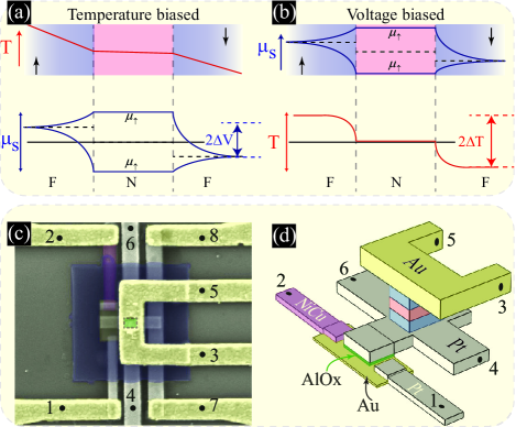
In this communication, we verify the ORR between these two coefficients by measuring both the spin-dependent Seebeck effect (SDSE) and spin-dependent Peltier effects (SDPE) in a single nanopillar spin valve under identical device conditions. The device, shown in Fig. 1(c,d), can be subjected to either an electrical or a thermal bias. An electrically isolated thermocouple is used to generate heat (in SDSE measurement) or record temperature differences (in SDPE measurement). We find that this relation is strictly valid in the linear (low bias) regime while deviation from the ORR is observed for the nonlinear (large bias) regime.
In the SDSE, an ac-current = through the thermocouple (contacts 1 and 2) results in Peltier heating/cooling () at the NiCu-Au and Au-Pt interfaces and Joule heating () along the entire current path. The resulting vertical temperature bias across the nanopillar results in the injection of a spin current from the ferromagnet (F) to the non-magnet (N). Here is the spin-dependent Seebeck coefficient in the ferromagnet Hatami et al. (2009); Slachter et al. (2010); Dejene et al. (2012); Jansen et al. (2012); Walter et al. (2011) and is the temperature bias across the nanopillar. It is possible to modulate this spin current and the associated spin accumulation by changing the magnetic state of the nanopillar Dejene et al. (2012); Hatami et al. (2009). Figure 1(a) shows the electrochemical potential profile for spin-up and spin-down electrons 111Here is defined such that spin-up corresponds to the spin with larger electrical conductivity. for a nanopillar spin valve subjected to a temperature bias, in the antiparallel configuration. The sum of the two voltage drops at the F/N interfaces is what is measured experimentally, using contacts 3 and 4.
The SDPE describes the reverse process, heating/cooling of the F/N interfaces as a result of a spin current = Gravier et al. (2006); Flipse et al. (2012) due to a gradient in . In this measurement a charge current flowing through the nanopillar (using contacts 3 and 4) generates a in the N. Because in N, a spin current in N does not transport heat to/away from the F/N interface. However, in F, and a spin current is associated with a net transport of heat depending on the magnetization of F. The resulting temperature change of at the two F/N interfaces is measured using contacts 1 and 2. Figure 1(b) shows this temperature profile for a nanopillar spin valve subjected to a voltage bias.
In the experiments, we look for similar first order responses both in the SDPE and SDSE as proof for ORR. Assuming nonlinear response of up to the third order the total voltage response can be written as where (=1,2…) is the order response. To distinguish these various responses we employ a multiple lock-in detection technique Slachter et al. (2010); Bakker et al. (2010). The first, second and third harmonic r.m.s. voltages measured at the lock-in amplifiers are related to as Vera-Marun et al. (2012); Bakker et al. (2010)
| (2a) | |||||
| (2b) | |||||
| (2c) | |||||
In the large biasing regime, the first harmonic resistance is not the equal to the first order response obtained from Eq. (2a) , in which case, a correction for the contribution from the third harmonic is needed, as discussed later. All electrical measurements are performed at room temperature with slowly varying ac current such that steady state temperature distribution is reached.
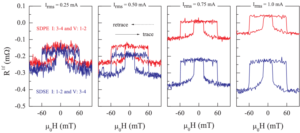
Figure 2 summarizes the main results of the paper where the first harmonic response is plotted as a function of applied magnetic field for various values of current. The contact configurations and the root-mean-square values of the charge current used are also specified in Fig. 2(a). The red curves correspond to a SDPE measurement (I: 3–4 and V :1–2) and the blue curves are when the role of the current and voltage leads is reversed (I: 1–2 and V:3–4). In the SDSE, for a current of 0.25 mA through the thermocouple, we observe a spin signal of 0.10 m due to the Peltier-heating induced vertical temperature gradient across the nanopillar. In the SDPE, for a similar current through the nanopillar, the observed background and spin valve signals are identical to the ones observed in the SDSE with both measurements collapsing on each other into one indistinguishable curve within the noise level. This indicates that the SDSE voltage across the nanopillar, governed by , is equal to the the SDPE induced thermovoltage at the thermocouple governed by . In other words, Eq. (1) is also valid for the spin-dependent counterparts of the charge Seebeck and Peltier coefficients. In the large biasing regime, say 1 mA, the spin signal of about m in the SDSE is twice larger than that in the SDPE. Furthermore, the background signal in the SDSE is also larger. These differences can be ascribed to deviation from the linear response regime due to higher order (nonlinear) thermoelectric effects.
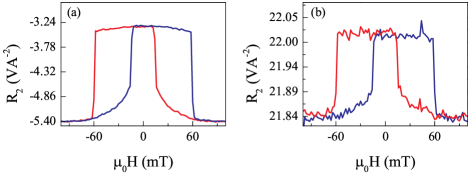
In addition to the first order response due to Peltier heating, we also observe higher order responses (Fig. 3 and 4). The magnetic field dependence of the second order response , for the SDSE (Fig. 3(a)) and SDPE (Fig. 3(b)), shows a spin signal of 1.9 VA-2 and 0.2 VA-2, respectively. The physical origin of the spin signal in the SDSE is identical to that in Fig. 2, but now due to the Joule-heating induced vertical temperature gradient across the nanopillar. The spin signal of observed in the SDPE (Fig.3(b)) is not however related to the spin-dependent Seebeck coefficient. Rather it originates from the change in the nanopillar resistance (and associated Joule heating) when the magnetic state of the nanopillar changes from the P to AP configuration Flipse et al. (2012).
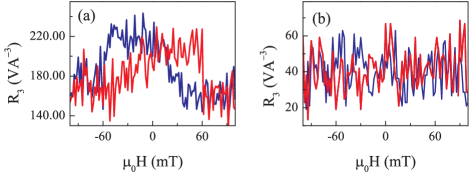
In the large biasing regime, a spin signal is also observed in the third order response of the SDSE measurement (Fig. 4(a)) while no spin signal (above the noise level) is present in the SDPE (Fig. 4(b)). This observation, that points to the presence of nonlinear thermoelectric effects, is consistent with the nonlinear bias- dependence observed in Fig. 2. From Eq. (3) it becomes clear that the combined effect of Joule and Peltier heating or concurrent changes in the the material properties of both the nanopillar and thermocouple can lead to the third order response Bakker et al. (2010). In this regime, the first harmonic voltage is not strictly linear with the applied current and hence should be corrected for the contribution from the third harmonic response as =+ (see Eq. (2a)).
Next, we discuss the bias dependence of the spin signals, the difference between the parallel and antiparallel voltages, for each of the first order (=), second order (=) and third order (=) responses (Fig. 5). While the uncorrected first harmonic signal in the SDSE (shown in the inset of Fig. 5(a)) is rather nonlinear with applied bias, the corrected first order response (main plot of Fig. 5(a)) scales linearly with the applied bias, both in the SDPE (triangles) and SDSE (circles). The slopes of the linear fits are also close to each other, within 20%, indicating validity of ORR over the entire bias range studied here. The current-dependence of the second order spin signal is also shown in Fig. 5(b). Absence of any deviation from the expected quadratic dependence on the applied bias supports our assumption of nonlinear response up to the third order.
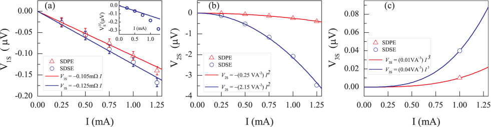
Note that the current at which = marks the point at which Joule heating is equal to Peltier heating. These current values of 50 A (in SDSE) and mA (in SDPE) can be taken as threshold values beyond which nonlinear thermoelectric processes become relevant for our nanopillar spin valves, which is consistent with Fig. 2.
For the sake of completeness, the bias dependence of the the third order spin signal is shown in Fig. 5(c). Because these higher order effects are only visible in the large biasing regime, only data at a current of 1 mA is shown. The solid lines are cubic dependencies extrapolated to the linear regime. These third order response spin signals are subtracted from the measured first harmonic spin signal (shown in Fig. 2) in order to obtain the first order spin signals in Fig. 5(a).
To understand the deviation from ORR we look at the thermovoltage in the when the local device temperature increases by =-. Noting that is linear with temperature as = where Bakker et al. (2010), the nonlinear thermovoltage signal reads
| (3) |
When and are a sizable fraction of , the second term in Eq. (3) becomes important leading to a deviation from ORR. Similarly, the thermovoltage in the SDPE can be nonlinear due to the temperature dependencies of the (of the thermocouple) and (of the ferromagnet).
Because it is difficult to keep track of interdependent changes in material parameters, we use a three dimensional spin dependent finite element model (3D-FEM)Slachter et al. (2011, 2010); Bakker et al. (2010) to understand these nonlinear effects. The spin-dependent charge current and heat current density are extended to include the temperature dependence of the input-material parameters as
| (4) |
where =+ is the temperature dependent electrical conductivity, is the temperature coefficient of resistance. The bulk values of are well tabulated in the literature () and that of thin films is known to be lower than the bulk value due to, for example, enhanced electron scattering at boundaries Zhang et al. (2005), which we use in our model. is the electronic thermal conductivity defined using the Wiedemann-Franz relation valid for metals at the temperatures of our experiments Bakker et al. (2012). Following Ref. Slachter et al., 2011, we define the spin-dependent electrical conductivity as = where -+ is the spin polarization of the electrical conductivity. The spin-dependent Seebeck coefficient is given by =. Material parameters for the modeling are taken from the literature Bakker et al. (2012); Dejene et al. (2013).
In order to calculate the spin signals observed in Fig. 5 we first extract from a separate measurement of the electrical spin valve (not shown here). The spin polarization of the Seebeck coefficient was also obtained from a separate measurement of the SDSE based on the Pt-Joule heater (also not shown here but discussed elsewhere Dejene et al. (2012, 2013)). Using the obtained values of and we calculate the SDPE and SDSE signals using the 3D-FEM. For the SDPE, we obtain spin signals of =95 , = VA-2 and = VA-3 for the first, second and third order signals, respectively, in agreement with the measured values. For the SDSE, the calculated values of =93 and = VA-2 are close to the measured values (see Fig. 5). The third order response = VA-3 in the SDSE is however three times larger. Although we do not understand this difference, owing to the good agreement of the calculated signals with the measured values, we conclude that nonlinear thermoelectric effects, as modeled here in terms of the temperature dependence of the transport coefficients, can describe both the linear and higher order responses.
In summary, we experimentally tested and verified the Onsager-Kelvin reciprocity relation for the spin-dependent Seebeck and Peltier coefficients and also provided the extent to which this reciprocity relation is respected. At small biases, when Joule heating is small, the Onsager reciprocity relation holds while, at large thermal/electrical biases, temperature dependence of both thermal and electrical transport coefficients drives the system into a non-linear regime where the basic assumption for ORR are not valid anymore. This deviation from ORR reciprocity is due mainly to nonlinear thermoelectric effects. It is therefore important to take nonlinear thermoelectric contributions into account in analyzing charge, spin and heat transport especially when the temperature gradient across a device is large. We also showed that higher order thermoelectric contributions, when not taken into account, could lead to apparent deviation from ORR.
The authors thank M. de Roosz, J.G. Holstein, H. Adema and B. Wolfs for technical assistance. I.J. Vera-Marun for reading the manuscript. This work is part of the research program of the Foundation for Fundamental Research on Matter (FOM) and is supported by NanoLab NL, EU-FP7 ICT grant 257159 MACALO, EU-FET Grant InSpin 612759, and the Zernike Institute for Advanced Materials.
References
- Onsager (1931) L. Onsager, Phys. Rev. 37, 405 (1931).
- Callen (1948) H. B. Callen, Physical Review 73, 1349 (1948).
- Miller (1960) D. G. Miller, Chemical Reviews 60, 15 (1960).
- Büttiker (1986) M. Büttiker, Phys. Rev. Lett. 57, 1761 (1986).
- Brataas et al. (2012) A. Brataas, A. D. Kent, and H. Ohno, Nature materials 11, 372 (2012).
- Jacquod et al. (2012) P. Jacquod, R. S. Whitney, J. Meair, and M. Büttiker, Phys. Rev. B 86, 155118 (2012).
- Bauer et al. (2010) G. E. Bauer, A. H. MacDonald, and S. Maekawa, Solid State Communications 150, 459 (2010).
- Bauer et al. (2012) G. E. Bauer, E. Saitoh, and B. J. van Wees, Nature materials 11, 391 (2012).
- Xu et al. (2006) J. Xu, S. Kjelstrup, D. Bedeaux, A. Røsjorde, and L. Rekvig, Journal of colloid and interface science 299, 452 (2006).
- Anatychuk and Luste (2005) L. I. Anatychuk and O. J. Luste, Modern thermodynamic theory of thermoelectricity, edited by D. Rowe, Thermoelectrics Handbook: Macro to Nano (Taylor & Francis, 2005) pp. 2–2–2–7.
- Slachter et al. (2010) A. Slachter, F. L. Bakker, J.-P. Adam, and B. J. van Wees, Nature Physics 6, 879 (2010).
- Erekhinsky et al. (2012) M. Erekhinsky, F. Casanova, I. K. Schuller, and A. Sharoni, Applied Physics Letters 100, 212401 (2012).
- Flipse et al. (2012) J. Flipse, F. L. Bakker, A. Slachter, F. K. Dejene, and B. J. v. Wees, Nature Nanotechnology 7, 166 (2012).
- Dejene et al. (2012) F. K. Dejene, J. Flipse, and B. J. van Wees, Phys. Rev. B 86, 024436 (2012).
- Dejene et al. (2013) F. Dejene, J. Flipse, G. Bauer, and B. van Wees, Nature Physics 9, 636 (2013).
- Matthews et al. (2013) J. Matthews, F. Battista, D. Sanchez, P. Samuelsson, and H. Linke, arXiv:1306.3694 [cond-mat] (2013).
- Avery and Zink (2013) A. D. Avery and B. L. Zink, Phys. Rev. Lett. 111, 126602 (2013).
- Hatami et al. (2009) M. Hatami, G. E. Bauer, Q. Zhang, and P. J. Kelly, Physical Review B 79, 174426 (2009).
- Jansen et al. (2012) R. Jansen, A. M. Deac, H. Saito, and S. Yuasa, Phys. Rev. B 85, 094401 (2012).
- Walter et al. (2011) M. Walter, J. Walowski, V. Zbarsky, M. Münzenberg, M. Schäfers, D. Ebke, G. Reiss, A. Thomas, P. Peretzki, M. Seibt, J. S. Moodera, M. Czerner, M. Bachmann, and C. Heiliger, Nature Materials 10, 742 (2011).
- Note (1) Here is defined such that spin-up corresponds to the spin with larger electrical conductivity.
- Gravier et al. (2006) L. Gravier, S. Serrano-Guisan, F. m. c. Reuse, and J.-P. Ansermet, Phys. Rev. B 73, 052410 (2006).
- Bakker et al. (2010) F. L. Bakker, A. Slachter, J.-P. Adam, and B. J. van Wees, Phys. Rev. Lett. 105, 136601 (2010).
- Vera-Marun et al. (2012) I. J. Vera-Marun, V. Ranjan, and B. J. van Wees, Nature Physics 8, 313 (2012).
- Slachter et al. (2011) A. Slachter, F. L. Bakker, and B. J. van Wees, Physical Review B 84, 174408 (2011).
- Zhang et al. (2005) X. Zhang, H. Xie, M. Fujii, H. Ago, K. Takahashi, T. Ikuta, H. Abe, and T. Shimizu, Applied Physics Letters 86, 171912 (2005).
- Bakker et al. (2012) F. L. Bakker, J. Flipse, and B. J. v. Wees, Journal of Applied Physics 111, 084306 (2012).