High-spin torus isomers and their precession motions
Abstract
- Background
-
In our previous study, we found that an exotic isomer with a torus shape may exist in the high-spin, highly excited states of 40Ca. The component of the total angular momentum, , of this torus isomer is constructed by aligning totally twelve single-particle angular momenta in the direction of the symmetry axis of the density distribution. The torus isomer executes precession motion with the rigid-body moments of inertia about an axis perpendicular to the symmetry axis. The investigation, however, has been focused only on 40Ca.
- Purpose
-
We systematically investigate the existence of exotic torus isomers and their precession motions for a series of even-even nuclei from 28Si to 56Ni. We analyze the microscopic shell structure of the torus isomer and discuss why the torus shape is generated beyond the limit of large oblate deformation.
- Method
-
We use the cranked three-dimensional Hartree-Fock (HF) method with various Skyrme interactions in a systematic search for high-spin torus isomers. We use the three-dimensional time-dependent Hartree-Fock (TDHF) method for describing the precession motion of the torus isomer.
- Results
-
We obtain high-spin torus isomers in 36Ar, 40Ca, 44Ti, 48Cr, and 52Fe. The emergence of the torus isomers is associated with the alignments of single-particle angular momenta, which is the same mechanism as found in 40Ca. It is found that all the obtained torus isomers execute the precession motion at least two rotational periods. The moment of inertia about a perpendicular axis, which characterizes the precession motion, is found to be close to the classical rigid-body value.
- Conclusions
-
The high-spin torus isomer of 40Ca is not an exceptional case. Similar torus isomers exist widely in nuclei from 36Ar to 52Fe and they execute the precession motion. The torus shape is generated beyond the limit of large oblate deformation by eliminating the components from all the deformed single-particle wave functions to maximize their mutual overlaps.
pacs:
21.60.Jz, 21.60.Ev, 27.40.+zI Introduction
Nuclear rotation is a key phenomenon to study the fundamental properties of finite many-body quantum systems. In particular, the rotation about the symmetry () axis produces a unique quantum object with its density distribution of a torus shape, as shown in our previous studies for 40Ca ich12 ; ich14 . In a classical picture for such rotation the oblate deformation develops with increasing rotational frequency due to the strong centrifugal force Cohen . However, such a collective rotation about the symmetry axis is quantum-mechanically forbidden. Instead, it is possible to construct extremely high-spin states by aligning individual angular momenta of single-particle motion in the direction of the symmetry axis BM77 ; Afan99 .
A drastic example is a high-spin torus isomer in 40Ca ich12 , where totally twelve single particles with the orbital angular momenta , , and align in the direction of the symmetry axis and construct a component of the total angular momentum of . Thus, a “macroscopic” amount of circulating current emerges in the torus isomer state, which may be regarded as a fascinating new form of the nuclear matter suggested by Bohr and Mottelson BM81 .
Another important kind of rotation is a collective motion that restores the symmetry spontaneously broken in the self-consistent mean field. The density distribution of the torus isomer largely breaks the symmetry about an ( or ) axis perpendicular to the symmetry axis ich14 . Below, we call this axis a perpendicular axis. Thus, the torus isomer can rotate about a perpendicular axis, although the collective rotation about the symmetry axis is quantum-mechanically forbidden. This rotational degree of freedom causes the precession motion of the system as a whole. Then, an interesting question arises how such a “femto-scale magnet” rotates collectively to restore the broken symmetry about a perpendicular axis.
A physical quantity characterizing such a collective rotation is the moment of inertia about a perpendicular axis. It has been theoretically recognized that an independent-particle configuration in a deformed harmonic-oscillator potential rotates with the rigid-body moment of inertia when the self-consistency between the mean-field potential and the density is fulfilled BMbook . However, measured moments of inertia for the case of the precession motion of prolately deformed nuclei are often much smaller than the rigid-body values even when pairing correlations are negligible del04 ; shi05 . This is because of shell effects in high- prolate isomers del04 . Although precession modes of high- oblate isomers have not been observed yet, their moments of inertia would be much reduced from the rigid-body values due to oblate shell structures at small deformations and81 .
From these observations, it might be conjectured that the moment of inertia about a perpendicular axis for the torus isomer also significantly deviates from the classical rigid-body value, because the torus isomer is a unique quantum object characterized by the alignment of angular momenta of independent-particle motions. It is thus surprising that the moment of inertia about a perpendicular axis, evaluated with the time-dependent Hatree-Fock (TDHF) method, from the rotational period of the precession motion of the torus isomer in 40Ca takes a value close to the classical rigid-body value ich14 . We analyzed the microscopic structure of the precession motion by using the random-phase approximation (RPA) method. In the RPA calculation, the precession motion of the torus isomer is generated by a coherent superposition of many one-particle-one-hole excitations across the sloping Fermi surface. We found that the precession motion obtained by the TDHF calculation is a pure collective motion well decoupled from other collective modes. In our previous studies, however, we focused only on the torus isomer of 40Ca. It is thus important to investigate whether torus isomers exist also in other nuclei and the properties of the precession motion found there are universal or not.
In this paper, we first perform a systematic investigation of the high-spin torus isomers for a series of even-even nuclei from 28Si to 56Ni. We show that the high-spin torus isomer of 40Ca is not an exceptional case. About forty years ago, Wong suggested, using a macroscopic-microscopic method, the possible existence of torus isomers at highly excited states of a wide region of nuclei Wong73 . Quite recently, Staszczak and Wong systematically explored the existence of torus isomers using the constrained cranked Hartree-Fock (HF) method and found some torus isomers at highly excited states in several nuclei Stas14 . However, they use the harmonic-oscillator basis expansion method, which is insufficient to treat unbound states. It is therefore difficult to examine the stability of the torus isomers against the nucleon emission in their calculation, although some of them would contain single particles in unbound states.
We then perform a systematic TDHF calculation to investigate the properties of the precession motion. For all the high-spin torus isomers obtained by the cranked HF calculation, we find the periodic solutions of the TDHF equation of motion, which describe the precession motions. Among them, the precession motion of the 60 torus isomer of 40Ca is particularly stable and continues for many periods.
To understand the microscopic origin of appearance of the torus isomers, we analyze the process during which the shell structure of the large oblate shape and that of the torus shape grow up from that of the spherical shape. Using the radially displaced harmonic-oscillator (RDHO) model Wong73 and the oblately deformed harmonic-oscillator potential, we finally discuss why the lowest components disappear from all the single-particle wave functions of the occupied states and how a large ‘hole’ region is created in the center of the nucleus to generate the torus shape.
This paper is organized as follows: In Section II, we describe the theoretical framework and parameters of the numerical calculation. In Section III, we present results of the systematic calculation for static and dynamical properties of the high-spin torus isomers including their precession motions. In Section IV, we analyze microscopic shell structures of the torus isomers and discuss the reason why the torus shape emerges beyond the limit of large oblate deformation. Finally, we summarize our studies in Section V.
II Theoretical framework
II.1 Cranked HF calculation
To investigate systematically the existence of high-spin torus isomer states in a wide range of nuclei, we use the cranked three-dimensional Skyrme HF method. To build high-spin states rotating about the symmetry axis of the density distribution ( axis), we add a Lagrange multiplier, , to the HF Hamiltonian, . Then, the effective HF Hamiltonian, , is written as , where denotes the component of the total angular momentum. We minimize this effective HF Hamiltonian with a given Lagrange multiplier, which is equivalent to the cranked HF equation given by .
For this purpose, we slightly modify the code Sky3d. The details of the code are given in Ref. sky3d . In the code, the single-particle wave functions are described on a Cartesian grid with a grid spacing of 1.0 fm, which is a good approximation for not only bound states but also unbound states in contrast to the harmonic-oscillator basis expansion. We take grid points for the , , and directions, respectively. This is sufficiently accurate to provide converged configurations. The damped-gradient iteration method gradient is used, and all derivatives are calculated with the Fourier transformation method.
In the calculation, we use the SLy6, SkI3, and SkM∗ Skyrme forces to check the interaction dependence of the calculated results. These effective interactions were well constructed based on nuclear bulk properties but differ in details; SLy6 as a fit which includes information on isotopic trends and neutron matter Cha97a , SkI3 as a fit taking into account the relativistic isovector properties of the spin-orbit force Rei95a , and SkM∗ as a widely used traditional standard Bar82 . However, except for the effective mass, the bulk properties (equilibrium energy and density, incompressibility, and symmetry energy) are comparable to each other. In the energy density functional, we omit terms depending on the spin density, because it may be necessary to extend the standard form of the Skyrme interaction in order to properly take into account the spin-density dependent effects todd_a (see also a review todd_b ), but such effects are inessential to the torus isomers.
II.2 Setting of initial configurations
In the cranked HF calculations, we first search for stable torus configurations in a series of even-even nuclei from 28Si to 56 Ni. We use, as an initial configuration of the HF calculation, an -cluster ring configuration placed on the - plane, as shown in Fig. 1 of Ref. ich12 . The -cluster wave function is described by a Gaussian function with the width of 1.8 fm. The center positions of the Gaussian functions are placed equiangularly along a circle with a radius of 6.5 fm on the plane. Only for the calculations of 52Fe with the SkM∗ interaction, we use a radius of 7.55 fm and a width of 1.63 fm. Using these initial configurations, we perform 15,000 HF iterations. We search for stable torus solutions varying from 0.5 to 2.5 MeV/ with a step of 0.1 MeV/. After these calculations, we check the convergence of the total energies, the density distributions, and the total angular momenta. In the calculations of the excitation energies, we subtract the expectation value of the center-of-mass motion in both the ground and the torus isomer states.
We next calculate all single-particle states including those above the Fermi energy. To calculate those, we use, as initial wave functions of the HF calculation, the single-particle wave functions of the RDHO model Wong73 . This model is a good approximation to the mean-field of torus-shaped isomers. In this model, the single-particle potential is given by
| (1) |
where denotes the nucleon mass, the oscillator frequency, and the radial and the components of the cylindrical coordinate system, and the radius parameter of the torus shape. Since the radial wave function of the lowest energy in the RDHO model is described by a shifted Gaussian function with the width , we determine from the radius of a cross section of a torus ring. The optimal values of and are determined through the global investigation mentioned above. Using this initial condition and a value of obtained by the global investigation, we perform the HF iteration over 20000 times and calculate the single-particle states up to the 40th for both protons and neutrons.
II.3 Sloping Fermi surface
It is important to note that the cranking term does not change the single-particle wave functions for rotation about the symmetry axis. Thus, it is useful to introduce the concept of “sloping” Fermi surface. As usual, the single-particle Hamiltonian is given by , where and denote the mean-field Hamiltonian and the component of the total angular momentum for each single particle, respectively. The eigenvalue of is written as , where denotes the Fermi energy at . The symbols and denote the single-particle energy and the eigenvalue of , respectively. By introducing the sloping Fermi surface defined by , we can rewrite as . Therefore, aligned configurations can be easily constructed by plotting the single-particle energies as a function of and tilting the Fermi surface in the plane. It is important to note that the value of to specify an aligned configuration is not unique. As we can immediately see in Figs. 3-7 below, individual configurations do not change for a finite range of .
II.4 Optimally aligned torus configurations
Let us focus on optimally aligned torus configurations where all the single-particle states below the sloping Fermi surface are occupied. They are expected to be more stable than other aligned configurations involving particle-hole excitations across the sloping Fermi surface. Before carrying out the cranked HF calculations, we can easily presume candidates of optimally aligned torus configurations. Since the effects of the spin-orbit potential are negligibly weak in the torus configurations, not only but also the component of the orbital angular momentum, , are good quantum numbers (, where denotes the component of the spin, ) ich12 . Single-particle states having the same value with different spin directions are approximately degenerated and simultaneously occupied . Thus, the lowest-energy configurations for the torus shapes at are , , , and for 28Si, , , , , and or for 32S, , , , for 36Ar, , , , , and or for 40Ca, , , , for 44Ti, , , , , and or for 48Cr, , , , for 52Fe, and , , , , and or for 56Ni.
For instance, in 40Ca, possible aligned configurations at are (i) , , , , and for [ (spin degeneracy) (isospin degeneracy)], (ii) , , , , , and for [], and (iii) , , , , , , , and for []. However, we could not obtain stable HF solutions for the configurations (i) and (iii): the centrifugal force is insufficient for stabilizing the configuration (i), while the last occupied single-particle state with is unbound for the configuration (iii). Indeed, we confirmed that the torus isomer configuration (iii) with slowly decays. In the systematic calculations, it is often difficult to discuss the stability of torus isomers when such unbound states are included. To avoid this difficulty, in this paper, we focus on torus configurations without involving unbound single-particle states.
II.5 TDHF calculation for the precession motion
For the stable torus isomers obtained above, we performed TDHF calculations to investigate their precession motions. The time evolution of the density distribution is determined by solving the TDHF equation of motion . When an impulsive force is provided in a direction perpendicular to the symmetry axis at , the torus isomer starts to execute the precession motion. This precession motion is associated with a rotation about a perpendicular axis, i.e., an axis perpendicular to the symmetry axis. In Ref. ich14 , we already showed that this precession motion is a pure collective motion to restore the broken symmetry and well described as coherent superpositions of many 1p-1h excitations across the sloping Fermi surface. We investigate whether other torus isomers also execute the precession motion well decoupled from other collective modes and whether their moments of inertia are close to the rigid-body values or not. In this way, we can also check the stability of the obtained torus isomers against given impulsive forces.

Figure 1 illustrates the schematic picture of the precession motion. At , the torus isomer is placed on the - plane with the angular momentum () along the axis in the laboratory frame. When an impulsive force is provided in the negative direction (the dotted line) at , the total angular momentum becomes (the dashed line). We call this vector the precession axis. After that, the symmetry axis of the density distribution in the body-fixed frame (the bold solid line) starts to rotate about the precession axis with the rotational angle . In the precession motion, the value is conserved and its direction is identical to the bold solid line. The tilting angle is defined as the angle between the bold solid and the dashed lines. Then, the moment of inertia for the rotation about a perpendicular axis, , can be estimated by , where denotes the rotational frequency of the precession motion. To build the first excited state of the precession motion, we provide an impulsive force such that the total angular momentum becomes .
To solve the TDHF equation, we use the code Sky3d and take the Taylor expansion of the time-development operator up to the 12th order. The setups of spatial grid points and interactions are the same as those of the cranked HF calculations described above. We start to perform calculations from the initial density distribution obtained by the cranked HF calculations. The time step of the TDHF calculations is 0.2 fm/. We calculate the time evolution until 3000 fm/. To excite the precession motion, we provide an impulsive force at by the external potential given by . This impulsive force gives an angular momentum in the negative direction at . The parameter is chosen such that the total angular momentum becomes .
| System | |||||||
|---|---|---|---|---|---|---|---|
| () | (MeV) | (fm-3) | (fm) | (fm) | (/MeV) | (/MeV) | |
| (SLy6) | |||||||
| 36Ar | 36 | 123.89 | 0.137 | 5.12 | 1.62 | 14.3 | 26.4 |
| 40Ca | 60 | 169.71 | 0.129 | 6.07 | 1.61 | 21.0 | 39.6 |
| 44Ti | 44 | 151.57 | 0.137 | 6.30 | 1.61 | 24.6 | 46.5 |
| 48Cr | 72 | 191.25 | 0.132 | 7.19 | 1.60 | 33.8 | 64.7 |
| 52Fe | 52 | 183.70 | 0.138 | 7.47 | 1.60 | 39.1 | 75.1 |
| (SkI3) | |||||||
| 36Ar | 36 | 125.15 | 0.146 | 5.01 | 1.58 | 13.7 | 25.3 |
| 40Ca | 60 | 173.52 | 0.138 | 5.90 | 1.58 | 19.9 | 37.5 |
| 44Ti | 44 | 153.02 | 0.146 | 6.17 | 1.58 | 23.6 | 44.6 |
| 48Cr | 72 | 193.66 | 0.141 | 7.00 | 1.57 | 32.0 | 61.3 |
| 52Fe | 52 | 183.70 | 0.147 | 7.31 | 1.57 | 37.5 | 71.9 |
| (SkM∗) | |||||||
| 36Ar | 36 | 124.80 | 0.131 | 5.16 | 1.65 | 14.6 | 26.9 |
| 40Ca | 60 | 167.84 | 0.122 | 6.17 | 1.64 | 21.8 | 41.0 |
| 44Ti | 44 | 152.20 | 0.131 | 6.36 | 1.64 | 25.1 | 47.5 |
| 48Cr | 72 | 192.40 | 0.125 | 7.30 | 1.63 | 34.9 | 66.7 |
| 52Fe | 52 | 187.08 | 0.132 | 7.55 | 1.63 | 40.0 | 76.7 |
III Results of calculation

III.1 Static properties
We have carried out a systematic search for stable torus isomers for the even-even nuclei from 28Si to 56Ni. The result of the calculation is summarized in Table 1. We obtain the stable torus isomers in 36Ar for , 40Ca for , 44Ti for , 48Cr for , and 52Fe for with all the three Skyrme interactions used in this study. On the other hand, we have not found any stable torus isomer in 28Si, 32S, and 56Ni. In Fig. 3, we plot the total density distributions of the torus isomers obtained in the cranked HF calculation with the SLy6 interaction.
The total density distribution of each of the torus isomers obtained in the cranked HF calculation is well fitted by the Gaussian function , where , , and denote the maximum value of the nucleon density, the radius of the torus ring, and the width of a cross section of the torus ring, respectively. The resulting values of the parameters, , , and , are tabulated in the middle part of Table 1. We see that the values and are almost constant for all the torus isomers. The interaction dependence of these values is weak. It is interesting that, in all the results, is smaller than the saturation nuclear density ( fm-3) and is close to the width of an alpha particle used in Brink’s -cluster model ( 1.46 fm) brink .
Using the total density distribution, we also calculate the rigid-body moments of inertia for rotation about a perpendicular axis, , and the symmetry axis, . The results are also shown in Table 1. Later, we shall compare these values for with those obtained by an analysis of the precession motions in the TDHF time evolution.
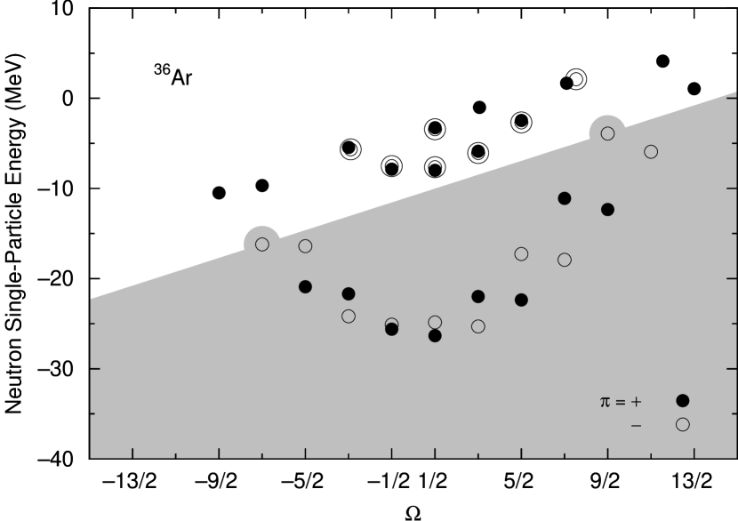
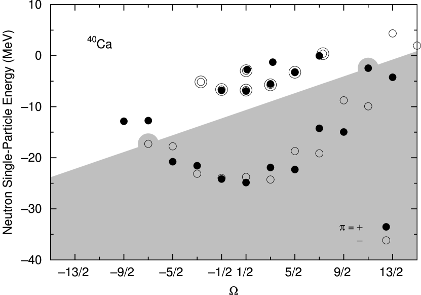
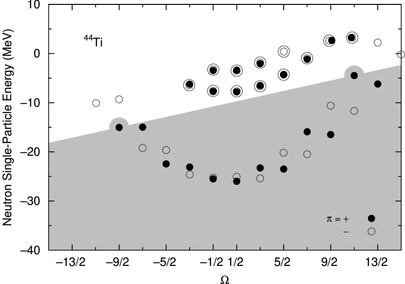
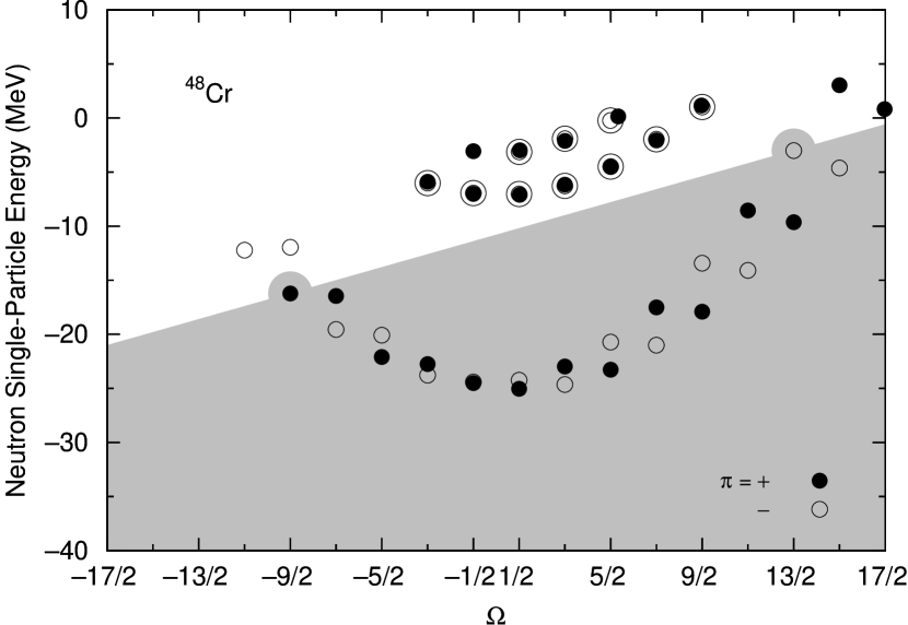
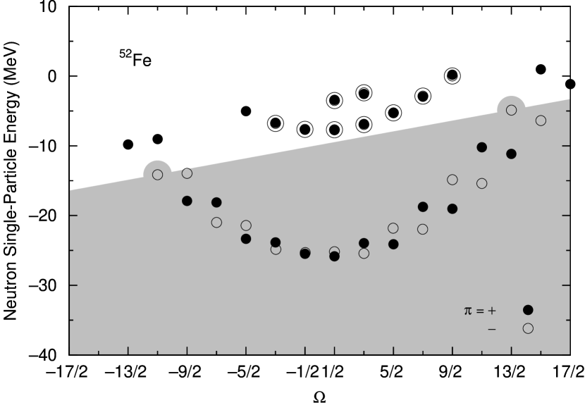
To investigate microscopic structures of the torus isomers, we plot in Figs. 3-7 neutron single-particle energies versus for each torus isomer calculated with the SLy6 interaction. In the figures, the solid and the open circles denote the positive- and negative-parity states, respectively. The gray area in each plot denotes the occupied states. In each plot, we see that the single-particle energies with the same are almost degenerate. This indicates that the effects of the spin-orbit force are negligibly small and is approximately a good quantum number in all the torus isomers. One may also notice that the Kramer’s degeneracy for a pair of single-particle states with is lifted. This is due to the time-odd components (dependent on the current density) of the cranked HF mean fields associated with the macroscopic currents, which are produced by the alignment of the single-particle angular momenta with large values of .
Because of the negligible spin-orbit splittings, the spin-orbit partners are always occupied simultaneously. Therefore, the values of the optimally aligned configurations are easily determined by summing up the values of the occupied single-particle states: they are [ = 9 (spin degeneracy) (isospin degeneracy) ] for 36Ar, [ = 15 ] for 40Ca, [ = 11 ] for 44Ti, [ = 18 ] for 48Cr, and [ = 13 ] for 52Fe.

We can estimate from the figures a region of for which each of the torus isomers stably exists. This is done by determining the steepest and the most gradual slopes of the Fermi surface for which the occupied single-particle configuration remains the same. The results are plotted in Fig. 8. The solid, dashed, and dotted lines denote the regions of for each of the stable torus isomers obtained with the SLy6, SkI3, and SkM∗ interactions, respectively. We see that the result does not strongly depend on the Skyrme interaction employed, although the width is weakly dependent on it.
III.2 Dynamic properties
| System | ||||
|---|---|---|---|---|
| () | (MeV/) | (MeV) | (/MeV) | |
| (SLy6) | ||||
| 36Ar | 37 | 450.1 | 2.75 | 13.5 |
| 40Ca | 61 | 402.5 | 3.08 | 19.8 |
| 44Ti | 45 | 651.0 | 1.90 | 23.7 |
| 48Cr | 73 | 554.5 | 2.24 | 32.6 |
| 52Fe | 53 | 872.8 | 1.42 | 37.3 |
| (SkI3) | ||||
| 36Ar | 37 | 427.9 | 2.90 | 12.8 |
| 40Ca | 61 | 378.6 | 3.28 | 18.6 |
| 44Ti | 45 | 624.4 | 1.99 | 22.7 |
| 48Cr | 73 | 524.5 | 2.36 | 30.9 |
| 52Fe | 53 | 839.0 | 1.48 | 35.9 |
| (SkM∗) | ||||
| 36Ar | 37 | 464.2 | 2.67 | 13.9 |
| 40Ca | 61 | 418.2 | 2.96 | 20.6 |
| 44Ti | 45 | 666.1 | 1.86 | 24.2 |
| 48Cr | 73 | 572.8 | 2.16 | 33.7 |
| 52Fe | 53 | 894.8 | 1.39 | 38.3 |

|

|

|

|

|
We carried out a systematic TDHF calculation for each of the torus isomers and found that that the TDHF time evolution of the density distribution is quite similar to that displayed in Fig. 2 of ich14 . Figure 9 shows the calculated time evolution of the precession motion for each of the torus isomers obtained with the SLy6 interaction. In each plot in Fig. 9, panels (a), (b), and (c) denote the total angular momentum, , the tilting angle, , and the rotational angle, , respectively. In panel (a) in each plot, we can see that the total angular momentum is conserved very well. This indicates that the TDHF calculations are sufficiently accurate. We find that the precession motion of the 40Ca torus isomer is especially stable [see panel (b) in each plot], where the rotational angle lineally increases with time, indicating that the rotation of the symmetry axis about the precession axis keeps a constant velocity through all the periods. This indicates that the strong shell effects responsible for the appearance of the torus isomer in 40Ca also stabilize the precession motion. We find that the precession motions emerge also for other torus isomers and they are stable at least for two periods. After that, however, the tilting angle gradually starts to fluctuate. Correspondingly, the rotational angle also starts to deviate from the linear time evolution [see panel (c) in each plot]. We have also carried out similar TDHF calculations with the use of the SkI3 and SkM∗ interactions. The results are similar to those shown above for the SLy6 interaction, which implies that the properties of the precession motion are robust and depend on the choice of the Skyrme interaction only weakly.
To evaluate the moment of inertia for the rotation about a perpendicular axis, we take the average of the two periods starting from during which the precession motion is especially stable. The results are tabulated in the third column of Table 2. Using these values, we calculate the frequency of the precession motion by and the moment of inertia for the rotation about a perpendicular axis by . The results are tabulated in the forth and fifth columns of Table 2. The obtained moments of inertia are very close to the rigid-body values tabulated in Table 1 for all the Skyrme interactions employed. As discussed in Ref. ich14 , these results indicate that the precession motions under consideration are pure collective motions generated by coherent superpositions of many 1p-1h excitations across the sloping Fermi surface.


IV Discussion
IV.1 Radial density distributions of individual single-particle states
Let us examine the radial density distributions of individual single-particle wave functions on the plane for the torus isomer of 40Ca. For this purpose, we interpolate the density distributions described with a Cartesian coordinate in the cranked HF calculations by means of a third-order B-spline function. After that, we transform those to a cylindrical coordinate representation []. We then integrate in the direction and obtain . The calculated results are plotted in the upper panel of Fig. 10.
As shown in Refs. ich12 ; ich14 , the RDHO model can describe well the microscopic structures of torus isomers. To illustrate this, we solve the Schrödinger equation with the RDHO potential, Eq. (1), by means of the deformed harmonic-oscillator basis expansion and calculate . In the calculation, we take fm and fm for the RDHO model and the same aligned single-particle configuration as that obtained by the cranked HF calculation for 40Ca. The obtained radial density distributions of the individual single-particle states are plotted in the lower panel of Fig. 10. Using these density distributions, we calculate the rigid-body moments of inertia about a perpendicular axis and the symmetry axis: they are /MeV and /MeV, respectively. These values are in good agreement with those obtained by the cranked HF calculation.
In Fig. 10, it is clearly seen that the radial density distributions of the individual single-particle states in the RDHO model are quite similar to those obtained by the cranked HF calculations. In particular, the peak positions of each radial density distribution are in good agreement between the two calculations. As a matter of fact, the peak position of each density distribution shifts to a larger with increasing orbital angular momentum. Looking into details of the density distributions obtained by the cranked HF calculations, one may notice that some radial density distributions with high angular momentum slightly shift due to the spin-orbit potential. In Fig. 4, the degeneracy of single-particle energies with the same high is indeed slightly broken for the spin-orbit partner with and () and that with and (). These spin-orbit effects are absent in the RDHO model.


IV.2 Shell structure of torus nucleus
Using the RDHO model, we next investigate shell structures of a torus isomer and examine how single-particle configurations change from spherical to torus shapes. Figure 11 shows a Nilsson diagram versus the parameter for 40Ca. At , the nuclear shape is spherical. At , a torus shape is well developed, which is a size similar to that obtained by the cranked HF calculations. Note that we take into account volume conservation inside an equi-potential surface of a torus isomer (see Ref. Wong73 and Appendix for the volume conservation in ). To eliminate the volume effect, we plot the single-particle energies in unit of . In this figure, we slightly shift the single-particle energies with higher in order to illustrate the degeneracy of the states.
In Fig. 11, we see the spherical major shell with at , where denotes the total number of oscillator quanta. With increasing , the single-particle energies with approach the asymptotic value given by , where , and denote the quantum number for oscillations in the and the radial directions, respectively. The energies of other single-particle states with larger in the same shell steeply decrease as a function of . At , the 10th and 11th (from the bottom) single-particle states with and () become lower than the 14th level with (the 1 state). These two single-particle states originate from those with a spherical harmonic-oscillator quantum number of (the state).
It is easy to understand these behaviors. As Wong showed in Ref. Wong73 , the single-particle energies for large are approximately given by . Thus, the single-particle energies belonging to the same shell are proportional to at lager .
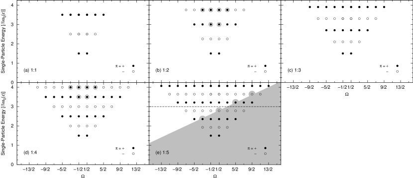
Figure 12 shows the single-particle energies in the RDHO model versus from to 4. At [Fig. 12 (a)], the familiar shell structure of the spherical harmonic-oscillator is seen. With increasing [Figs. 12 (b)-(d)], single-particle energies with high rapidly decrease. Then, the single-particle energies start to form parabolic structures. At [Fig. 12 (e)], two important properties emerge: (i) the curvature of the parabolic structure becomes large, and (ii) the single-particle energies within the same shell are proportional to . These two properties play an essential role in stabilizing the torus isomers when single particles are aligned in the direction of the symmetry axis.
It is surprising that the single-particle shell structure of the RDHO model at is very similar to that of Fig. 5 obtained by the cranked HF calculation. The RDHO model is therefore a good approximation for describing the microscopic structures of the torus isomers.
IV.3 Emergence of the torus shape beyond the limit of oblate deformation

Lastly, let us discuss the reason why the torus nucleus emerges beyond the limit of large oblate deformation. In the spherical harmonic-oscillator potential, the radial wave function of the lowest single-particle state is given by a Gaussian function peaked at the center (the state): accordingly, the central part of the total density distribution is quite stable. Then, a question arises why such a stable and robust wave function vanishes and how the torus shape emerges.
To investigate why the state disappears, we calculate the single-particle energies for the deformed harmonic-oscillator potential as a function of oblate deformation. Figure 13 shows the obtained Nilsson diagram versus the aspect ratio of the short (the direction) to the long (the radial direction) axes for an ellipsoidal nuclear surface (oblate deformation). The aspect ratio 1:1 corresponds to the spherical shape. The aspect ratio 1:5 corresponds to an oblate shape with the same aspect ratio as that of the torus isomer of 40Ca obtained by the cranked HF calculation. The single-particle energies are plotted in unit of , where denotes the frequency of the harmonic-oscillator potential depending on the Nilsson perturbed-spheroid parameter to describe ellipsoidal nuclear shapes. In , the volume conservation inside an equi-potential surface is taken into account Nilsson . In the figure, we see that some single-particle energies associated with high spherical major shells rapidly decrease with increasing oblate deformation. At the aspect ratio 1:5, the last occupied state for 40Ca () originates from that with a spherical harmonic-oscillator quantum number of (the state).
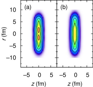
In Figs. 14, the single-particle energies are plotted versus at each aspect ratio. We see that the shell gaps of the single-particle energies decrease with increasing oblate deformation. However, the basic pattern of deformed shell structure does not change, in contrast to that of the RDHO model shown in Fig. 12. In Fig. 14 (e), the dashed line denotes the Fermi level for at . The neutron density distribution, , for the occupied configuration is shown in Fig. 15 (a). The densities in the direction are integrated. Two prominent peaks are seen in the density distribution. We next consider an aligned single-particle configuration at MeV/. This corresponds to a value for the torus isomer of 40Ca. The occupied states at this are shown by the gray area in Fig. 14 (e). By the alignments, totally five single-particle states with [505] and [505] (), [404] and [404] (), and [402] () are occupied (the asymptotic Nilsson label is used here). On the other hand, the single particle states with and (), (), and and () become unoccupied. Summing up the aligned single-particle angular momenta, we obtain the neutron contribution to the component of the total angular momentum . Taking into account the proton contribution as well, we finally obtain the total angular momentum for this oblate configuration, which is close to that of the torus isomer for 40Ca obtained by the cranked HF calculation. The neutron density distribution at MeV/ is shown in Fig. 15 (b). The two peaks seen in Fig. 15 (a) vanish and densities in the central region become flat and stretch to radial direction, as the single-particle states with high are occupied.
Figure 16 shows the density distributions of individual single-particle states of special interest at aspect ratio 1:5. The densities for the direction in the cylindrical coordinate are integrated. The dashed line shows the density distribution of the lowest state. On the other hand, the solid lines depict those of the aligned , 4, and 5 states mentioned above that are occupied at MeV/. The single-particle density distributions of these aligned states peak around fm. Apparently, the overlap between the aligned nucleons and the nucleons in the lowest state is very small. Namely, the lowest state largely containing the spherical component is rather isolated from the others. To gain the attractive interactions between nucleons, the total system tends to maximize the overlaps between the density distributions of individual single particles. Thus, it would be energetically favorable to concentrate the densities of individual nucleons around fm. In this way, the nucleus with extremely large oblate deformation may start to generate the torus shape. This seems to be the basic reason why a large ’hole’ is created in the central region of the nucleus by eliminating the spherical wave function.
V Summary
We have systematically investigated the existence of high-spin torus isomers for a series of even-even nuclei from 28Si to 56Ni using the cranked HF method. We found the stable torus isomers from 36Ar to 52Fe for all the Skyrme interactions used in this study. In the obtained torus isomers, the components of the total angular momentum are for 36Ar, 60 for 40Ca, 44 for 44Ti, 72 for 48Cr, and 52 for 52Fe. We fitted the density distribution of each of the obtained torus isomers with the Gaussian function. We also analyzed the microscopic structure of the obtained torus isomers by plotting the single-particle energies versus and using the concept of sloping Fermi surface. We determined the regions of for which the obtained torus isomers can stably exist in each Skyrme interaction. The dependence of the obtained results on the Skyrme interactions employed is found to be weak.
We have also performed TDHF calculations to explore the properties of the precession motion rotating with angular momentum , which is built on each of the obtained torus isomer with . For all the obtained torus isomers, the precession motion emerges and the symmetry axis rotates about the precession axis for at least two periods. It was found that the precession motion of the 60 isomer in 40Ca is especially robust and stably rotates for many periods, We obtained similar results for all the Skyrme interactions used, We also estimated the moment of inertia for the rotation about a perpendicular axis from the calculated rotational periods of the precession motion. The obtained moments of inertia are close to the rigid-body values for all the obtained torus isomers.
We have discussed the radial density distribution of each single-particle wave function in the high-spin torus isomer of 40Ca. We showed that the density distributions are well approximated by those of the RDHO model. We then discussed how the shell structure develops from spherical to torus shapes. There are two important mechanisms for stabilizing torus isomers: (i) the development of the major shells consisting of single-particle states whose energies are given by , where and is the component of orbital angular momentum. (ii) a large value of that reduces the energies of high single-particle states. We finally discussed why the components of all the single-particle wave functions vanish and generate a torus shape. We showed that in an aligned single-particle configuration with extremely large oblate deformation, the overlaps between the density distributions of the lowest single-particle state and the aligned high- single-particle states become very small due to the strong centrifugal force. To gain the attractive interaction energy as much as possible, nucleons tend to maximize the overlaps of their wave functions. An optimal configuration beyond the limit of large oblate deformation is the one creating the localization of single-particle density distributions around a torus ring. This seems to be a basic mechanism of the emergence of high-spin torus isomers.
Acknowledgements.
TI was supported in part by MEXT SPIRE and JICFuS. This work was undertaken as part by the Yukawa International Project for Quark-Hadron Sciences (YIPQS). J.A. M. was supported by BMBF under contract number 06FY9086 and 05P12RFFTG, respectively.*
Appendix A PARAMETERS AND VOLUME CONSERVATION IN THE RDHO MODEL
In the RDHO model, we take the oscillator frequency, , to conserve the inner volume of an equi-potential energy surface. It is given by
| (2) |
where and denotes the oscillator frequency in the spherical limit. Here, we take MeV, where is the number of nucleons, and and denote the average densities of a torus isomer and the ground state, respectively Stas14 . In the calculations, we use .
References
- (1) T. Ichikawa, J. A. Maruhn, N. Itagaki, K. Matsuyanagi, P.-G. Reinhard, and S. Ohkubo, Phys. Rev. Lett. 109, 232503 (2012).
- (2) T. Ichikawa, K. Matsuyanagi, J. A. Maruhn, and N. Itagaki, Phys. Rev. C89, 011305(R), (2014).
- (3) S. Cohen, F. Plasil and W.J. Świa̧tecki, Ann, Phys. 82, 557 (1974).
- (4) A. Bohr, in Elementary Modes of Excitation in Nuclei, Proceedings of the International School of Physics “Enrico Fermi”, Course LXIX, edited by A. Bohr and R. A. Broglia (North-Holland, Amsterdam, 1977), p. 3.
- (5) A.V. Afanasjev, D.B. Fossan, G.J. Lane, and I. Ragnarsson, Phys. Rep. 322, 1 (1999).
- (6) A. Bohr and B.R. Mottelson, Nucl. Phys. A354, 303c (1981).
- (7) A. Bohr and B.R. Mottelson, Nuclear Structure, Vol. II (World Scientific, Singapore, 1998).
- (8) M. A. Deleplanque , S. Frauendorf, V. V. Pashkevich, S. Y. Chu, and A. Unzhakova, Phys. Rev. C 69, 044309 (2004).
- (9) Y. R. Shimizu, M. Matsuzaki, and K. Matsuyanagi, Phys. Rev. C 72, 014306 (2005).
- (10) C. G. Andersson, J. Krumlinde, G. Leander, Z. Szymański, Nucl. Phys. A 361, 147 (1981).
- (11) A. Staszczak and C. Y. Wong, arXive:1312.3413.
- (12) C.Y. Wong, Ann. Phys. 77, 279 (1973).
- (13) J.A. Maruhn, P.-G. Reinhard, P.D. Stevenson, A.S. Umar, Comp. Phys. Comm. 185, 2195 (2014).
- (14) P.-G. Reinhard, and R. Y. Cusson, Nucl. Phys. A378, 418 (1982).
- (15) E. Chabanat, P. Bonche, P. Haensel, J. Meyer, and R. Schaeffer, Nucl. Phys. A627, 710 (1997).
- (16) P.-G. Reinhard and H. Flocard, Nucl. Phys. A584, 467 (1995).
- (17) J. Bartel, P. Quentin, M. Brack, C. Guet, and H.-B. Hakansson, Nucl. Phys. A386, 79 (1982).
- (18) P. Wen, L-G. Cao, J. Margueron and H. Sagawa, Phys. Rev. C89, 044311 (2014).
- (19) J.R. Stone and P.-G. Reinhard, Prog. Part. Nucl. Phys. 58, 587 (2007).
- (20) D. Brink, Proceedings of the International School of Physics “Enrico Fermi”, Course 36, Varenna, 1965, edited by C. Bloch (Academic Press, London, 1966), pp. 247-277.
- (21) S. G. Nilsson and I. Ragnarsson, Shapes and Shells in Nuclear Structure, (Cambridge University Press, Cambridge, 1995).