Charge-Stripe Order in a Parent Compound of Iron-based Superconductors
Abstract
Charge ordering is one of the most intriguing and extensively studied phenomena in correlated electronic materials because of its strong impact on electron transport properties including superconductivity. Despite its ubiquitousness in correlated systems, the occurrence of charge ordering in iron-based superconductors is still unresolved. Here we use scanning tunneling microscopy to reveal a long-range charge-stripe order and a highly anisotropic dispersion of electronic states in the ground state of stoichiometric FeTe, the parent compound of the Fe(Te, Se, S) superconductor family. The formation of charge order in a strongly correlated electron system with integer nominal valence (here Fe2+) is unexpected and suggests that the iron-based superconductors may exhibit more complex charge dynamics than originally expected. We show that the present observations can be attributed to the surpassing of the role of local Coulomb interaction by the poorly screened longer-range Coulomb interactions, facilitated by large Hund’s rule coupling.
Charge order (CO) has been observed in a wide range of strongly correlated electron systems (SCESs), such as manganites dagotto05 ; coey04 , magnetite senn12 , cobaltates cwik09 , nickelates billinge13 , and cuprates uchida95 ; lawler10 ; comin14 ; neto14 . Such ubiquity comes unexpected since the two generic leading energy scales in electron systems—the kinetic energy and local Coulomb interaction —generally favor uniform charge distribution instead. However, it has been shown that CO may result from a compromised interplay of charge with the spin gunnarsson89 and/or orbital Volja ; Brink degrees of freedom. Moreover, the bad-metal behavior of SCESs Emery ; note:bad-metal implies that CO can also be driven by the poorly screened longer-range Coulomb interactions. Usually, the SCESs that exhibit CO have fractional nominal valence due to charge doping or mixed valence in nature note:valence , which allows charge fluctuation free of the energy penalty from . An exception comes when is surpassed by Hund’s rule coupling Mazin . The ubiquity of CO is thus a manifestation of electronic correlation effects dagotto05 . Experimentally, CO is readily characterized by diffraction, x-ray scattering, and scanning tunneling microscopy (STM) techniques uchida95 ; lawler10 ; comin14 ; neto14 . These features of CO have made its study an effective route to understanding SCESs in general and helping resolve some current grand problems in condensed matter physics, such as high-temperature superconductivity in cuprates and colossal magnetoresistance in manganites in particular.
Naturally, it is desirable to know how CO emerges in iron-based superconductors (FeSCs) hosono08 , which appear to have all the aforementioned ingredients for CO: they contain the charge, spin, orbital degrees of freedom yin09 and show bad-metal behavior si08 . Oddly enough, to date, convincing evidence of CO in FeSCs is still lacking. Compared with the other SCESs, FeSCs are indeed somehow different. For example, the origin of strong electron correlation in FeSCs is attributed to the Hund’s rule coupling instead of medici14 ; yin11_NM ; yin10 ; yin12 likely due to the suppression of via strongly coupled charge multipole polarizations of Fe and anion ma14 . This peculiar charge dynamics could mediate electron pairing for superconductivity sawatzky09 . On the other hand, the suppression of also favor the formation of CO. Hence, finding CO in FeSCs has become an important step to our understanding of FeSCs and CO mechanisms in SCESs.
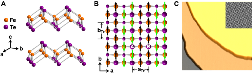
Here we report the direct observation of long-range static charge order in FeSCs with systematic STM measurement on FeTe, the parent compound of the Fe(Te,Se,S) family of FeSCs wu08 ; gu10 ; bao09 ; dai09 ; xiang09 . FeTe was chosen because of its simple structure (Fig. 1A) and arguably strongest electronic correlation in the FeSC system yin11_NM . The ground state of bulk FeTe is known to possess the metallic bicollinear antiferromagnetic (AFM) spin order bao09 ; dai09 ; xiang09 , named after the pattern of alternating two columns of Fe sites with spin-up and two columns of Fe sites with spin-down (see Fig. 1B). Alternatively, the two columns of Fe sites of the same spin can be viewed as a zigzag chain formed by the nearest Fe-Fe bonds; this AFM order is called -type in the context of manganites yin10 . The latter viewpoint bridges these two important classes of SCESs: FeSCs and manganites. In fact, it has been shown that various material-dependent magnetic orders in FeSCs yin10 ; yin12 and manganites hotta03 are unified in a spin-fermion model. In this work, we find that CO in FeTe peculiarly follows the same bicollinear -type order, a pattern that has not been observed or predicted before in the charge channel. Even more strikingly, this CO is realized in a SCES with integer nominal valence. We suggest that the -type CO can be well accounted for by including long-range Coulomb interaction in the spin-fermion model.
The experiments were carried out in a Unisoku UHV 3He STM system equipped with a molecular beam epitaxy (MBE) chamber for in situ film growth. Single crystal Fe1+xTe samples usually contain a sizeable amount of excessive Fe atoms, which are known to bring substantial extrinsic effects such as transforming the metallic FeTe to a semiconductor bao09 ; note:extrinsic . To avoid these extrinsic effects, we grew stoichiometric FeTe single-crystalline films with MBE in ultra-high vacuum (UHV) and performed the STM experiment in the same UHV system SI . Topography of the Te-terminated FeTe film (Fig. 1C) shows the atomically flat surface with broad terraces. The step height is 0.63 nm. The image with atomic resolution (Fig. 1C, inset) exhibits a quasi-square lattice of Te atoms with lattice constant of 3.8 Å. Previous studies bao09 ; dai09 on bulk FeTe show a tetragonal to monoclinic structural phase transition at K with a simultaneous development of the -type AFM order (i.e., ).
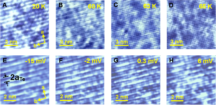
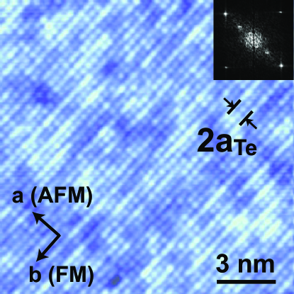
The STM images at different temperatures (Fig. 2, A to D) shows that the structural transition is correlated with the appearance of a striped pattern. The pattern is barely visible at 63 K and completely disappears at K. The stripes are formed by the Te atoms and only visible at very low bias voltage, which rules out the possibility of surface reconstruction. Measurement of lattice constants by STM identifies the stripe orientation as the FM direction (b-axis) SI .
The energy dependence of the stripes is presented in Fig. 2, E to H, with the STM images of the same location under different bias voltages. The pattern is only visible at low energy within meV of the Fermi level. Inside this energy window, the stripes are static and remain unchanged with different bias voltage. As clearly demonstrated in the figures, the bright stripes of Te atoms in the topmost layer alternate with the dark ones in the AFM direction. Therefore the periodicity is , the same as that of the -type spin order. To gain more insight into the origin of the stripes, we mark two adjacent Te atoms in Fig. 1B as “A” and “B”. If A is bright, then B must be dark. Here the key point is that these two sites A and B differ in the configuration of their neighboring Fe spins: A is adjacent to one up and three down spins on Fe, while B to one down and three up spins. Since the charge fluctuations on Fe cations and Te anions are strongly coupled ma14 , the contrast displayed by the Te atoms actually reflects the existence of a charge-stripe order in the Fe plane. In addition, the concurrence of stripe and AFM order at the structural transition indicates that the charge-stripe order is tied to the long-range -type AFM order.
We note that previous neutron scattering studies Igor revealed the existence of strong spin fluctuations in the FeTe system. It is shown that the long-range -type AFM order only makes a small and very low-energy contribution to the entire spin dynamics, while the higher energy part is governed by other competing orders such as the plaquette spin order Igor ; yin12 . Thus, the correlation between CO and AFM helps explain the appearance of stripes at low energy.
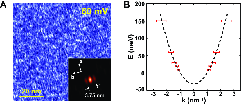
Another relevant finding is that the electrons are much more itinerant in the FM direction than in the AFM direction. An anisotropic dispersion is revealed by scanning tunneling spectroscopy (STS) measurement. The STS detects the differential tunneling conductance , which gives a measure of the local density of states (LDOS) of electrons at energy . The mapping was performed on the surface of FeTe. At each data point, the feedback was turned off and the bias modulation was turned on to record . This procedure resulted in a series of spatial mapping of LDOS at various bias voltages. A typical mapping at 60 mV is shown in Fig. 3A. The autocorrelation analysis (inset of Fig. 3A) reveals a wave vector exclusively along the b-axis. A parabolic dispersion (Fig. 3B) is obtained by plotting the wave vector versus energy. The dispersion is highly anisotropic and only observed in the FM direction. The parent compound of iron-pnictide superconductor Ca(Fe1-xCox)2As2 also exhibits similar property davis10 . However, the present results for FeTe are nontrivial because of the different electron transport behavior in FeTe from that in the iron pnictides. In FeTe, the electric conductivity in the FM direction is larger than that in the AFM direction feng13 , while the opposite is observed for iron pnictides feng13 ; fisher10 . The consistency between the anisotropy in band dispersion and electric conductivity in FeTe unambiguously indicates that the itinerant electrons hop much more easily along the FM direction.
The highly anisotropic itinerancy is a reminiscence of the electron behavior in the manganites hotta03 and suggests that the itinerant electrons in FeTe move in a localized spin background and are favorably described by the double-exchange mechanism in the spin-fermion model yin10 . In this model, the itinerant electrons and the localized spins are coupled by the strong on-site Hund’s rule coupling , which is a FM exchange interaction. Therefore, an itinerant electron hopping between two sites with the same (opposite) localized spins will experience zero () energy barrier, leading to dispersive (nondispersive) electronic states along the FM (AFM) directions and the so-called double-exchange ferromagnetism anderson55 . The metallic -type AFM spin order in FeTe itself results from a compromised interplay between the double-exchange ferromagnetism and the antiferromagnetism that originates from the superexchange between the localized spins yin10 .
The observed charge-stripe order in FeTe can be readily reproduced by inclusion of long-range intersite Coulomb interactions (thanks to the poor screening in FeTe) into a model that can account for the metallic -type AFM spin order with highly anisotropic dispersion. The Hamiltonian reads , where
| (1) |
Here is the electron number operator on the th Fe site. If refers to the th-neighbor, one may use to approximate the screened Coulomb potential, where is the dielectric constant of the material and the th-neighbor Fe-Fe bond length. Then the Fe square sublattice leads to .
We first analyze the effect of alone without considering the kinetic energy. Let , where is the averaged filling of the itinerant electrons per Fe site. Then, the problem can be mapped to a classical spin model plus a constant. Substituting by , we arrive at the -- spin model, which is known to yield the -type AFM “spin” order when and xiang09 . This numerical condition is satisfied by . Hence, the -- model alone is ready to yield the observed -type charge order with on the “spin”-up sites and on the “spin”-down sites.
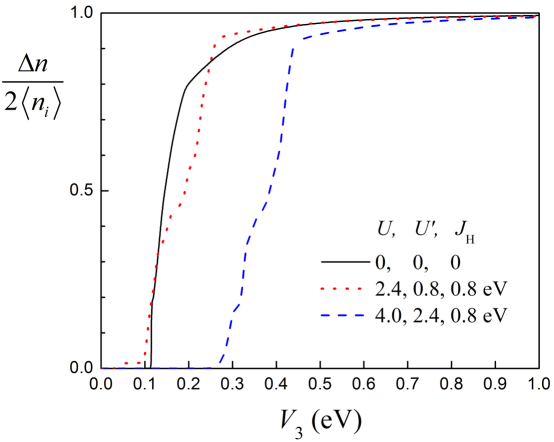
The above charge-stripe order is expected to be weakened by the kinetic energy contributed from . However, the negligible kinetic energy along the AFM direction compared with that along the FM direction warrants the Stoner-type instability of “spin” polarization, namely the charge difference between the spin-up Fe site and the spin-down Fe site. Therefore, the charge-stripe order still survives even for small . The situation is explicitly shown in fig. S2, where is calculated using the aforementioned spin-fermion model for . In the supplemental material SI , we also demonstrate how the effect of local Coulomb interactions is suppressed by the double-exchange mechanism, which is necessary for to be effective in driving the CO instability.
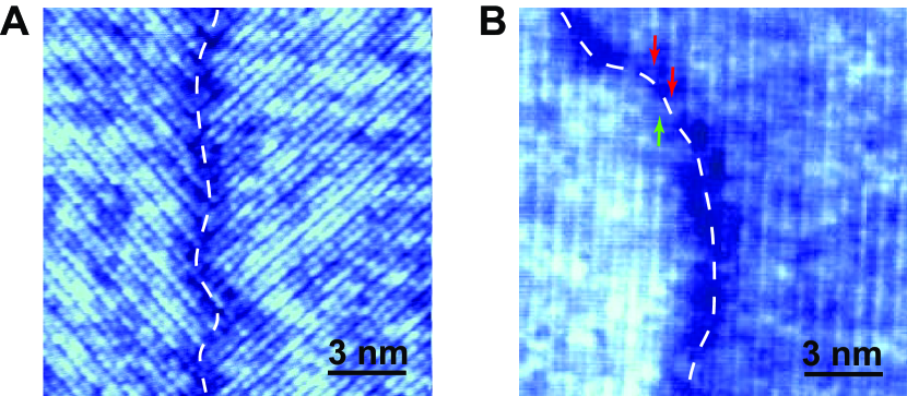
Finally, the stripe structure of FeTe indicates two types of domain boundaries: orthorhombic twin boundary and anti-phase boundary. Both of them have been observed and are shown in Fig. 4. The continuity of the charge stripes ends at the domain boundaries (marked by the dash lines). The stripes either rotate by 90∘ (Fig. 4A) or shift by (Fig. 4B) upon crossing the boundary while the ()-Te lattice in the topmost layer remains uninterrupted. This rules out the effects of possible defects (for example, excessive Fe atoms) as the cause of the observed electronic nematicity.
The -type charge-stripe order revealed in stoichiometric FeTe with integer nominal valence affirms the ubiquity of the phenomenology of CO in SCESs, and suggests a more complex charge dynamics and pairing mechanism than originally expected. It implies that the effect of local Coulomb interaction can be surpassed by the poorly screened longer-range Coulomb interactions in FeSCs, and that bad metallicity, strong correlation from Hund’s rule coupling, and strongly coupled charge multipole polarizations of Fe and anion are key to understanding FeSCs.
References
- (1) E. Dagotto, Science 309, 257 (2005).
- (2) M. Coey, Nature 430, 155 (2004).
- (3) M. S. Senn, J. P. Wright, J. P. Attfield, Nature 481, 173 (2012).
- (4) M. Cwik et al., Phys. Rev. Lett. 102, 057201 (2009).
- (5) A. M. M. Abeykoon, E. S. Božin, W.-G. Yin, G. Gu, J. P. Hill, J. M. Tranquada, S. J. L. Billinge, Phys. Rev. Lett. 111, 096404 (2013).
- (6) J. M. Tranquada, B. J. Sternlieb, J. D. Axe, Y. Nakamura, S. Uchida, Nature 375, 561 (1995).
- (7) M. J. Lawler et al., Nature 466, 347 (2010).
- (8) R. Comin et al., Science 343, 390 (2014);
- (9) E. H. da Silva Neto et al., Science 343, 393 (2014).
- (10) J. Zaanen, O. Gunnarsson, Phys. Rev. B 40, 7391 (1989).
- (11) D. Volja, W.-G. Yin, W. Ku, Europhys. Lett. 89, 27008 (2010).
- (12) J. van den Brink et al., Phys. Rev. Lett. 83, 5118 (1999).
- (13) V. J. Emery, S. A. Kivelson, Physica C 263, 44 (1996).
- (14) Bad metals are referred to materials whose electric resistivity shows metallic-like temperature dependence but large (usually of the order of m cm) absolute value and whose optical Drude weight is finite but small.
- (15) For example, Mn3.5+ (Mn3+/Mn4+) in La0.5Ca0.5MnO3, Fe2+/Fe3+ in Fe3O4, Cu2+/Cu3+ in La1.875Ba0.125CuO4.
- (16) I. I. Mazin et al., Phys. Rev. Lett. 98, 176406 (2007).
- (17) Y. Kamihara, T. Watanabe, M. Hirano, H. Hosono, J. Am. Chem. Soc. 130, 3296 (2008).
- (18) C.-C. Lee, W.-G. Yin, W. Ku, Phys. Rev. Lett. 103, 267001 (2009).
- (19) Q. Si, E. Abrahams, Phys. Rev. Lett. 101, 076401 (2008).
- (20) L. de’ Medici, G. Giovannetti, M. Capone, Phys. Rev. Lett. 112, 177001 (2014).
- (21) Z. P. Yin, K. Haule, G. Kotliar, Nature Materials 10, 932 (2011).
- (22) W.-G. Yin, C.-C. Lee, W. Ku, Phys. Rev. Lett 105, 107004 (2010).
- (23) W.-G. Yin, C.-H. Lin, W. Ku, Phys. Rev. B 86 081106 (2012).
- (24) C. Ma, L. Wu, W.-G. Yin, H. Yang, H. Shi, Z. Wang, J. Li, C. C. Homes, Y. Zhu, Phys. Rev. Lett. 112, 077001 (2014).
- (25) G. A. Sawatzky, I. S. Elfimov, J. van den Brink, J. Zaanen, Europhys. Lett. 86, 17006 (2009).
- (26) F.-C. Hsu et al., Proc. Nat. Acad. Sci. 105, 14262 (2008).
- (27) N. Karayama et al., J. Phys. Soc. Jpn. 79, 113702 (2010).
- (28) W. Bao et al., Phys. Rev. Lett. 102, 247001 (2009).
- (29) S. L. Li et al., Phys. Rev. B 79, 054503 (2009).
- (30) F. J. Ma, W. Ji, J. P. Hu, Z.-Y. Lu, T. Xiang, Phys. Rev. Lett. 102, 177003 (2009).
- (31) T. Hotta, M. Moraghebi, A. Feiguin, A. Moreo, S. Yunoki, E. Dagotto, Phys. Rev. Lett. 90, 247203 (2003).
- (32) A previous STM study [Y. Kawashima et al., Physica B 407, 1796 (2012)] of a semiconducting Fe1+xTe film reported the -type CO, where charge alternates among nearest neighboring Fe sites. The semiconducting nature of that film implies that the CO is likely caused by extrinsic effects.
- (33) Materials and methods are available as online supporting material.
- (34) I. A. Zaliznyak et al., Phys. Rev. Lett 107, 216403 (2011).
- (35) T.-M. Chuang, M. P. Allan, J. H. Lee, Y. Xie, N. Ni, S. L. Bud’ko, G. S. Boebinger, P. C. Canfield, J. C. Davis, Science 327, 181 (2010).
- (36) J. Jiang et al., Phys. Rev. B 88, 115130 (2013).
- (37) J.-H. Chu, J. G. Analytis, K. De Greve, P. L. McMahon, Z. Islam, Y. Yamamoto, I. R. Fisher, Science 329, 824 (2010).
- (38) P.W. Anderson, Phys. Rev. 100, 675 (1955).
- (39) This work was supported by National Natural Science Foundation and Ministry of Science and Technology of China and by the U.S. Department of Energy (DOE), Office of Basic Energy Science, under Contract No. DE-AC02-98CH10886.
Supporting Materials for
Observation of Long-Range Charge Order in Stoichiometric FeTe Films
by W. Li, W.-G. Yin, L. L. Wang, K. He, X. C. Ma, Q.-K. Xue, and X. Chen
I Materials and Methods
The FeTe (001) film was prepared on the graphitized 6H-SiC (0001) substrate. High-purity Fe (99.995%) and Te (99.9999%) were evaporated from two standard Knudsen cells. The growth was performed in the Te-rich conditions with a nominal Te/Fe flux ratio of 15 to avoid excess Fe in the film, while the substrate temperature was held at 310∘C. The growth follows the typical layer-by-layer mode. The as-grown films were directly transferred to STM. A polycrystalline PtIr STM tip was used in the experiments. The STM topographic images were processed using WSxM (www.nanotec.es). We studied the samples with the thickness of , , and unit cells and found similar results. We present here the measurements on the -unit-cell sample.
II Supporting Online Text and Figures
Identification of the FM and AFM directions from topographic images
The image with atomic resolution in Fig. S1 exhibits a quasi-square lattice of Te atoms with lattice constant of 3.8 Å. Previous studies Sbao09 ; Sdai09 on bulk FeTe show a tetragonal to monoclinic (approximately orthorhombic) structural phase transition at K with a simultaneous development of the -type antiferromagnetic (AFM) order (i.e., ); the long axis of the Te lattice is along the AFM direction (the a-axis in Fig. 1B). To determine the lattice orientation of the film, we performed the Fourier transform of Fig. S1 (see the inset of Fig. S1). The lattice constant along the a-axis is 2% larger than that along the b-axis. We therefore identify the a-axis as the AFM direction and b-axis as the ferromagnetic (FM) direction in the film.
Calculation of charge order in the spin-fermion model
The effective Hamiltonian becomes . The spin-fermion model , where the Fe and orbitals were treated to host itinerant electrons and the rest Fe orbitals were treated as an effective localized spin, was proposed as a minimal model to unify the various magnetic orders observed in FeSCs, such as metallic E-type in FeTe, metallic C-type in LaOFeAs and BaFe2As2 Syin10 ; Syin12_SST and insulating block-type in K2Fe4Se5 and BaFe2Se3 Syin12 , -type in TaFeTe3 Ske12 ; Sxu14 , and FM in CuFeSb Sqian12 , etc. It reads Syin10 ; Syin12_SST ; Slv10 ; Sweng09 ; Svishwanath09 ; Sliang12
| (S1) | |||||
where denotes the annihilation operator of an itinerant electron with spin or in the or orbital on site . ’s are the electron hopping parameters. is the Pauli matrix and is the localized spin whose magnitude is . is the effective Hund’s rule coupling between the itinerant electrons and the localized spins. is the AF superexchange couplings between the localized spins; in particular, and are respectively the nearest-neighbor (NN) and next-nearest-neighbor (NNN) ones. The , , and terms on the second line of Eq. S1 describes the on-site intraorbital Columbic, interorbital orbital Columbic, and Hund’s rule interactions between the itinerant electrons, respectively. The filling of the itinerant electrons is three per Fe site, corresponding to the high-spin configuration of Fe Syin09 .
To minimize the number of free parameters, we take and as free parameters, set and , and keep the other parameters the same as previously used for FeTe Syin10 , notably eV. We also keep the same treatment of the localized spins as Ising spins, which has been shown to suffice for the problem of interest.
In Fig. S2, we present the calculated as a function of for three typical cases: (i) (black solid line), (ii) eV, eV, and eV (red dotted line), and (iii) eV, eV, and eV (blue dashed line). It shows that as increases, the -type CO saturates to as discussed in the main text. As increases, the CO is suppressed considerably as expected. The results for the first two cases are comparable to each other. This is understandable as the double-exchange effect: The strong term tends to align the spins of the itinerant electrons with the localized spins, thus suppressing the effect of and the effective interaction between the itinerant electrons becomes , which is zero in case (ii). This justifies the use of the noninteracting case (i) to approximate the interacting case (ii) Syin10 ; Syin12_SST ; Syin12 . We show that the CO starts to appear at small eV.
References
- (1) W. Bao et al., Phys. Rev. Lett. 102, 247001 (2009).
- (2) S. L. Li et al., Phys. Rev. B 79, 054503 (2009).
- (3) W.-G. Yin, C.-C. Lee, and W. Ku, Phys. Rev. Lett 105, 107004 (2010).
- (4) W.-G. Yin, C.-C. Lee, and W. Ku, Superconductor Science & Technology 25, 084007 (2012).
- (5) W.-G. Yin, C.-H. Lin, and W. Ku, Phys. Rev. B 86 081106(R) (2012).
- (6) X. Ke et al., Phys. Rev. B 85, 214404 (2012).
- (7) M. Xu et al., arXiv:1310.7348 (2014).
- (8) B. Qian et al., Phys. Rev. B 85, 144427 (2012).
- (9) W. Lv, F. Krüger, and P. Phillips, Phys. Rev. B 82, 045125 (2010).
- (10) S. P. Kou, T. Li, and Z. Y. Weng, Europhys. Lett. 88, 17010 (2009).
- (11) A. M. Turner, F. Wang, and A. Vishwanath, Phys. Rev. B 80, 224504 (2009).
- (12) S. Liang, G. Alvarez, C. Şen, A. Moreo, and E. Dagotto, Phys. Rev. Lett 109, 047001 (2012).
- (13) C.-C. Lee, W.-G. Yin, W. Ku, Phys. Rev. Lett. 103, 267001 (2009).