Light focusing in the Anderson Regime
Anderson localization is a regime in which diffusion is inhibited and waves (also electromagnetic waves) get localized. Here we exploit adaptive optics to achieve focusing in disordered optical fibers in the Anderson regime. By wavefront shaping and optimization, we observe the generation of a propagation invariant beam, where light is trapped transversally by disorder, and show that Anderson localizations can be also excited by extended speckled beams. We demonstrate that disordered fibers allow a more efficient focusing action with respect to standard fibers in a way independent of their length, because of the propagation invariant features and cooperative action of transverse localizations.
Adaptive techniques have turned around optics allowing not only to correct aberrations in the image formation but also to focus light beams through curtains of dielectric scatterersVellekoop et al. (2010); Vellekoop and Mosk (2008a); Popoff et al. (2010) by employing the most transmitting modesKim et al. (2012). The focusing may be achieved by wavefront-shaping, using spatial light modulators (SLMs) and applying a specific phase distribution to the input beam to correct the random delay imposed by the diffusive propagation. Focusing by wavefront shaping has opened the way to many novel applications Katz et al. (2012); Akbulut et al. (2011); van Putten et al. (2011) as it can be realized in any disordered structure, even if, so far, it has been studied only within the diffusive regime, in the absence of mechanisms of wave-localization. It is well accepted that if the strength of disorder increases beyond a critical value, a transition called Anderson localizationSheng (1990); Lagendijk et al. (2009); Anderson (1958) takes place. In the proximity of this regime, there is a drastic reduction of diffusion, and ultimately an absence of transport. Being originated by interference, Anderson localization is common to all kind of waves and has been demonstrated for matter wavesRoati et al. (2008), soundHu et al. (2008) and entangled photonsCrespi et al. (2013). For light it is difficult to achieve localization in three dimensions (3D) Sperling et al. (2012) because the scattering strength has to be strong enough to satisfy the IoffeRegel criterion, while absorption has to be negligibleAnderson (1985); Wiersma et al. (1997); John (1987); Störzer et al. (2006). On the contrary, two dimensional (2D), or transverse, localization De Raedt et al. (1989) is always obtained in sufficiently large samples and has various analogies with the focusing through adaptive processes : they are both coherent phenomena and allow to trap light in a tiny spot. Transverse localization De Raedt et al. (1989) occurs in systems disordered in the plane perpendicular to the direction of propagation: it has been demonstrated in arrays Pertsch et al. (2004), in optical lattices Schwartz et al. (2007), and in plastic Karbasi et al. (2012a) and glass Karbasi et al. (2012b) fibers.
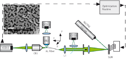
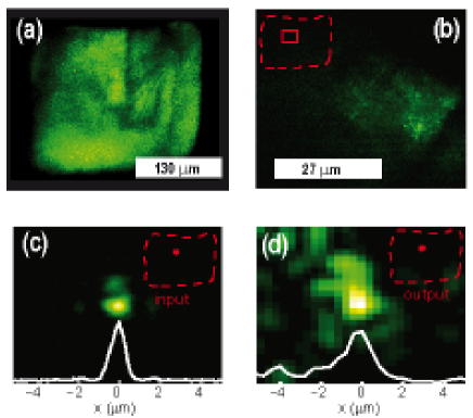
The role of transverse localization in speckle focusing has never been previously investigated. Here we study the interplay between the focusing process and Anderson localization and demonstrate that the absence of diffusion cooperates with the optimization protocol to improve focusing effectiveness. We use an optical fiber (without cladding) with transverse disorder and binary refractive index modulation Lagendijk et al. (2009); Karbasi et al. (2012c, d), (see inset of figure 1). The index contrast of the order of 0.1 results from the difference between between Polystyrene (PS, refractive index ) and polymethylmethacrylate (PMMA ). We estimate the value of losses in 0.5 Db/cm. This value will be further decreased of at least two orders of magnitude exploiting advanced fabrication techniques. Moreover a relevant part of the losses are due to the input and output coupling and can be reduced by improving the fiber cutting procedure. The disordered fiber has been fabricated by melding 40,000 strands of polystyrene and 40,000 strands of polymethyl methacrylate. The mixture of strands was fused together and redrawn to a square shaped fiber with a lateral size m Karbasi et al. (2012a). Samples have length between 1.2 and 8 cm. Light generated by a continuous-wave (CW) laser with wavelength nm (vertical polarization) is injected in the system after being modulated by an SLM in the phase only configuration (experimental setup shown in Fig. 1). Fig. 2a shows the fiber output when the input is completely illuminated (horizontal polarization is retrieved to eliminate ballistic light). The focusing effect is found to be independent of the input polarization. Such a structure supports strong localization (as already demonstrated in Karbasi et al. (2012a, c)), having a refractive index mismatch three orders of magnitude larger than in the seminal experiment of Schwartz et al. (2007), and also allows image transmission Karbasi et al. (2014).
Independently of the spatial shape of the input beam, some particular hotspots at fixed positions in the fiber output are observed, as in Fig. 2b, which shows the transmitted intensity from the output face of the fiber. Fig. 2b is obtained by averaging random input configurations realized by a random SLM phase-mask producing a m speckled spot at the fiber entrance (see also Fig. 3a,b). The presence of hotspots appearing at fixed positions independently of the input mask is connected with the presence of extremely efficient transport channelsKim et al. (2012). The high transmitting channels are Anderson modes of the fibers, i.e., transverse localizations (TL) that retain a fixed transverse profile along propagation. This is demonstrated by injecting light by a long working-distance objective (numerical aperture , resulting focused spot size 0.7 m), which feeds selectively a single mode. In this configuration the input and the output spots are similar in size (Fig. 2c,d), and appear at the same transverse location in the fiber. This confirms that the excited mode is an eigenmode of the fiber, and its shape and position are not affected by the propagation.
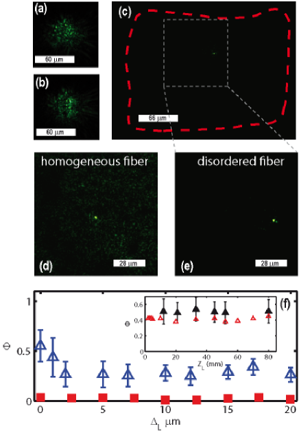
Having located such efficient channels, we applied a feedback algorithm to improve the intensity in one of the observed hotsposts. Our approach is a standard one, very similar to that described inVellekoop and Mosk (2008b): a random phase shift is applied to a segment of the SLM, which is divided in a 2323 matrix composed by 529 segments. The CCD 1 in Fig. 1 grabs an image of the output and the algorithm retains the change in the phase mask only if the intensity in the hotspot increases, otherwise the previous phase shift is restored. At the end of the optimization procedure (after 529 steps) more than one half of the fiber output has been channeled into the target point, i.e., into a four micrometer area (fiber lateral side m). The input speckled beam ( m waist, obtained by a mm focal lens), is shown in Fig. 3a (before the optimization) and Fig. 3b (at the end of the optimization). Fig. 3c shows the image of the output focused beam, and demonstrates that, in the Anderson regime, one half of the transmitted energy is focused in a m2 squared area centered at the target, the ratio of the intensity at focus with respect to the average background is .
For comparison, we repeated the experiment by using an homogeneous disorder-free standard fiber and found very different results: the optimized focused spot contains only of the total transmitted intensity, and the ratio of the intensity at focus with respect to the average background is of the order of 50; this is a result comparable with the state of the art in multimode fibersDi Leonardo and Bianchi (2011); Čižmár and Dholakia (2011, 2012). The same comparison cannot be done with photonic crystal fibers, which typically support few modes thus making impossible the optimization protocol. The approach proposed here has several advantages also if compared with fiber bundles: the absence of an alignment requiring mechanical movement of the optics, and a larger set of possible outputs. All the possible positions of the output facet may be targeted also simultaneously generating multiple foci. Images of the focus for the homogeneous PMMA fiber and for the Anderson fiber (ALF) are shown in panels 3d and 3e, respectively.
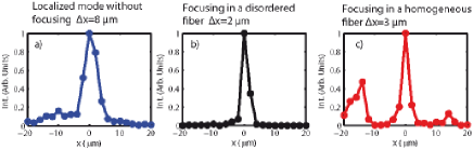
A further comparison between various cases is in Fig. 4 in which the profiles of the focus in various configurations are reported.
At variance with the standard PMMA fiber, the presence of TL introduces a strong dishomogeinity of the response in the transverse direction. We performed a set of measurements (shown in Fig. 3f) with variable distance from an high transmitting transport channel, determined by the position of the output hotspots as described above. Specifically, instead of maximizing the intensity in correspondence of a chosen hotspot, we maximized the intensity at a distance from it, and measured the focusing efficiency, defined as the ratio between the power channeled in this shifted position (at the end of the optimization procedure) and the total output power from the fiber. The result in Fig. 3f shows that rapidly decreases when moving far away from the hotspot, which hence represents the most efficient position of the focusing (and corresponds to a TL). On the contrary, the homogeneous fiber (red squares in Fig. 3f) shows no significant variation of in terms of the target position .
This difference is ascribed to the presence of TL. To demonstrate that the propagation invariant TL is the leading mechanism to concentrate light at the target point, we repeated the focusing experiments with fibers with varying length . The inset in Fig.3f shows that is nearly indepedent of , as is also confirmed by results from the numerical simulation described below. The most effective focusing in the disordered case is due to the presence of the Anderson localization that inhibits light diffusion and practically eliminates the background speckle pattern. We stress that the TL focusing action is concomitant with the standard focusing action, which involves all the modes of the fibers and results in an enhancement of the intensity at the focus.
To further confirm this scenario, we resorted to the numerical simulation of the paraxial equation approximating the propagation of an optical field (with the beam intensity) in the ALF Arnaud (1976). In dimensionless units this equation reads as
| (1) |
with , a=A, being a reference intensity, and the average refractive index. The transverse disorder is given by a term representing the random fluctuations of the refractive index in the transverse plane , and and :
Eq. (1) is an approximate scalar model for beam propagation in a high index contrast ALF. However, while fully vectorial calculations allow determining the supported mode profiles, the simulation of the optimization procedure and beam propagation is computationally prohibitive beyond the scalar approximation in Eq. (1).
The transverse bound states (2D Anderson localizations) in this simplified model, are given by with
| (2) |
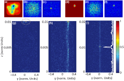
Results after Eq.(1) for high index contrast (): (d) ground state, (e) input after optimization, (f) output after optimization, bottom panel (h): intensity distribution in the section of fiber in correspondence of the output spot along propagation direction. Note that the localization since the beginning of propagation and further enhanced at the end; (i) as in (h) for a doubled propagation length and with the optimization target located in the middle of the fiber. The white line is the intensity profile in correspondence of the focus Vs. Z.
Because of the mentioned computational limitations, we approximate the disorder distribution by Gaussian random potential, such that . We remark that the distribution of the disorder is coarse-grained in the numerical simulations by the adopted discretization, and by retaining as independent Gaussian variables the noise values in different grid points. We verified that the discretization does not affect the reported results by increasing the number of grid points in the numerical simulations. We also considered binary random potentials (not reported) with results similar to what follows. The Gaussian potential is also included in a rectangular well to account for the interface between the fiber and air. The strength of the potential is determined by the refractive index contrast: the index jump between PS and PMMA is as the latter varies on a spatial scale m of the order of , we have , which gives for our fiber; for comparison we take for the weak disorder cases. In our trials we varied in a range of two decades and found no qualitative changes with respect to the representative cases reported in the following; we stress that the considered propagation distances correspond to those in our experiments (in our normalized units corresponds to m).
We first determine the 2D eigenmodes in our simplified model from (2), as given in Fig. 5a (Fig. 5d) for the low (high) index contrast case. The mode with the stronger localization (ground state) is chosen as the target for the optimization. By solving equation (1), the field profile at each point (x, y and z ) is calculated; the input condition is generated as done in the experiments and results in speckled beam are shown in Fig.5b (Fig 5e) for the low (high) index contrast. After a random modification of the phase at the input, the solution of (1) is calculated, and the change is retained if the intensity at the target point increases. When the index contrast is very small (i.e., far from the strong localization condition), the focusing appears only at the very end of the fiber (figure 5g), that is at a well defined z, as it occurs in 3D with standard materialsVellekoop et al. (2010), or in multimode optical fibers Di Leonardo and Bianchi (2011). When the degree of localization is strong (figure 5h), the focus appears in correspondence of a TL, propagating along the direction z, being enhanced at the fiber tip.
In Fig. 4i we show the intensity profile after an optimization for a target located in the middle of fiber, and found a pronounced intensity peak in the focus. This shows that most of the energy is carried by the TL located at the target, and that the other modes interfere constructively to enhance the local optimized intensity. As in experiments, the numerical simulations furnish an efficiency independent of the fiber length (see inset of Fig. 3f). The numerically calculated is found to be slightly smaller than the experimentally measured value due to the limited resolution of the simulations, where we also considered very small fiber lengths not accessible in the experiments ( mm in Fig. 3f).
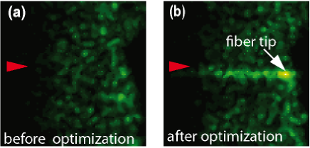
We experimentally verified the existence of such propagating mode appearing together with the focus in the ALF by measuring the light scattered at one side of the fiber, by using a microscope and CCD 3 (see Fig. 1). Results are reported in Fig. 6 where the arrow indicates the direction of light propagation. Fig. 6a shows the image of the ALF side before the focusing-optimization process, and Fig. 6b shows the same fiber section at the end of the focusing-optimization process. In the latter case, intensity is increased not only at the fiber end-tip but also along the z axis.
In conclusion, we investigated light focusing in random media by an adaptive technique in the presence of transverse Anderson localization. By applying an iterative optimization process we were able to feed a localized mode by a spatially modulated beam. The quality of the obtained focus differs strongly from what reported in 3D disordered structures and in standard fibers, because light couples to localized modes traveling for centimeters. We found that the inhibition of diffusion imposed by the Anderson regime boosts the amount of light coupled to the target, lowering the detrimental contribution to the focusing due to the background speckle pattern by several orders of magnitude. The transversal localization hence non-trivially cooperate in the focusing action, and two mechanisms are found to occur: on one hand, the TL located at the target point transports most of the energy, on the other hand, the other modes interfere locally and enhance the intensity. The resulting focusing efficiency is found to be nearly independent of the fiber length, and this may ultimately lead to a variety of applications based on the transport and focusing of light in specific points also located in distant positions within disordered matter.
Acknowledgements S.K. and A.M. are supported by grant number 1029547 from the National Science Foundation.
References
- Vellekoop et al. (2010) I. Vellekoop, A. Lagendijk, and A. Mosk, Nature Photonics 4, 320 (2010).
- Vellekoop and Mosk (2008a) I. Vellekoop and A. Mosk, Physical review letters 101, 120601 (2008a).
- Popoff et al. (2010) S. Popoff, G. Lerosey, R. Carminati, M. Fink, A. Boccara, and S. Gigan, Physical review letters 104, 100601 (2010).
- Kim et al. (2012) M. Kim, Y. Choi, C. Yoon, W. Choi, J. Kim, Q.-H. Park, and W. Choi, Nature Photonics 6, 583 (2012).
- Katz et al. (2012) O. Katz, E. Small, and Y. Silberberg, Nature Photonics (2012).
- Akbulut et al. (2011) D. Akbulut, T. J. Huisman, E. G. van Putten, W. L. Vos, and A. P. Mosk, Opt. Express 19, 4017 (2011).
- van Putten et al. (2011) E. van Putten, D. Akbulut, J. Bertolotti, W. Vos, A. Lagendijk, and A. Mosk, Physical review letters 106, 193905 (2011).
- Sheng (1990) P. Sheng, Scattering and Localization of Classical Waves in Random Media (World Scientific, Singapore, 1990).
- Lagendijk et al. (2009) A. Lagendijk, B. van Tiggelen, and D. S. Wiersma, Phys. Today 62, 24 (2009).
- Anderson (1958) P. W. Anderson, Physical review 109, 1492 (1958).
- Roati et al. (2008) G. Roati, C. D Errico, L. Fallani, M. Fattori, C. Fort, M. Zaccanti, G. Modugno, M. Modugno, and M. Inguscio, Nature 453, 895 (2008).
- Hu et al. (2008) H. Hu, A. Strybulevych, J. Page, S. E. Skipetrov, and B. A. van Tiggelen, Nature Physics 4, 945 (2008).
- Crespi et al. (2013) A. Crespi, R. Osellame, R. Ramponi, V. Giovannetti, R. Fazio, L. Sansoni, F. De Nicola, F. Sciarrino, and P. Mataloni, Nature Photonics (2013).
- Sperling et al. (2012) T. Sperling, W. Buehrer, C. Aegerter, and G. Maret, Nature Photonics 7, 48 (2012).
- Anderson (1985) P. W. Anderson, Philosophical Magazine B 52, 505 (1985).
- Wiersma et al. (1997) D. S. Wiersma, P. Bartolini, A. Lagendijk, and R. Righini, Nature 390, 671 (1997).
- John (1987) S. John, Phys. Rev. Lett. 58, 2486 (1987).
- Störzer et al. (2006) M. Störzer, P. Gross, C. M. Aegerter, and G. Maret, Physical review letters 96, 063904 (2006).
- De Raedt et al. (1989) H. De Raedt, A. Lagendijk, and P. de Vries, Physical review letters 62, 47 (1989).
- Pertsch et al. (2004) T. Pertsch, U. Peschel, J. Kobelke, K. Schuster, H. Bartelt, S. Nolte, A. Tünnermann, and F. Lederer, Physical review letters 93, 053901 (2004).
- Schwartz et al. (2007) T. Schwartz, G. Bartal, S. Fishman, and M. Segev, Nature 446, 52 (2007).
- Karbasi et al. (2012a) S. Karbasi, C. R. Mirr, P. G. Yarandi, R. J. Frazier, K. W. Koch, and A. Mafi, Optics Letters 37, 2304 (2012a).
- Karbasi et al. (2012b) S. Karbasi, T. Hawkins, J. Ballato, K. W. Koch, and A. Mafi, Opt. Mater. Express 2, 1496 (2012b).
- Karbasi et al. (2012c) S. Karbasi, C. R. Mirr, P. G. Yarandi, R. J. Frazier, K. W. Koch, and A. Mafi, Optics Letters 37, 2304 (2012c).
- Karbasi et al. (2012d) S. Karbasi, C. R. Mirr, R. J. Fraizer, P. G. Yarandi, K. W. Koch, and A. Mafi, Optics Express 20, 18692 (2012d).
- Karbasi et al. (2014) S. Karbasi, R. J. Frazier, K. W. Koch, T. Hawkins, J. Ballato, and A. Mafi, Nat. Commun. 5, 3362 (2014).
- Vellekoop and Mosk (2008b) I. Vellekoop and A. Mosk, Optics Communications 281, 3071 (2008b).
- Di Leonardo and Bianchi (2011) R. Di Leonardo and S. Bianchi, Optics express 19, 247 (2011).
- Čižmár and Dholakia (2011) T. Čižmár and K. Dholakia, Opt. Express 19, 18871 (2011).
- Čižmár and Dholakia (2012) T. Čižmár and K. Dholakia, Nature communications 3, 1027 (2012).
- Arnaud (1976) J. A. Arnaud, Beam and Fiber Optics (Academic Press, New York, 1976).