RTL2RTL Formal Equivalence : Boosting the Design Confidence
Abstract
Increasing design complexity driven by feature and performance requirements and the Time to Market (TTM) constraints force a faster design and validation closure. This in turn enforces novel ways of identifying and debugging behavioral inconsistencies early in the design cycle. Addition of incremental features and timing fixes may alter the legacy design behavior and would inadvertently result in undesirable bugs. The most common method of verifying the correctness of the changed design is to run a dynamic regression test suite before and after the intended changes and compare the results, a method which is not exhaustive. Modern Formal Verification (FV) techniques involving new methods of proving Sequential Hardware Equivalence enabled a new set of solutions for the given problem, with complete coverage guarantee. Formal Equivalence can be applied for proving functional integrity after design changes resulting from a wide variety of reasons, ranging from simple pipeline optimizations to complex logic redistributions. We present here our experience of successfully applying the RTL to RTL (RTL2RTL) Formal Verification across a wide spectrum of problems on a Graphics design. The RTL2RTL FV enabled checking the design sanity in a very short time, thus enabling faster and safer design churn. The techniques presented in this paper are applicable to any complex hardware design.
1 Introduction
Graphics designs are increasingly finding their relevance in new market segments like smartphones, tablets and a faster churn of optimized designs is most desirable to meet the market requirements. Verifying the design for incremental changes is an involved challenge and is the most time consuming and critical aspect of the design process. Traditional DV methods mandate a compromise between breadth of coverage and resources available. We have pioneered methodologies to enable formal verification at the design stage which help a faster churn of RTL and early stabilization.
Formal verification has proved to be an ideal candidate to verify tough SoC design challenges due to its ability to exhaustively verify all possible complex scenarios without any need for a test bench or input stimulus. With formal, a designer or verification engineer need not spend time stimulating all possible scenarios as the formal engines carry out this task under the hood and result in increased confidence. This eliminates the uncertainty of not verifying a scenario which is either difficult to think of or is missed due to the complexity of the design.
Formal equivalence is a known field of research and the most common application of the methodology is in checking the correctness of the netlist generated by the design synthesis against the RTL which is synthesized. The ability to formally determine functional equivalence between RTL models is a key enabler in physically aware front-end design methodologies that are being practiced in high performance designs. Earlier Combinational Equivalence checking tools needed state matching designs which were tested with equivalent functional maps. With the advent of new methodologies and sequential equivalence tools where the sequentially different implementations of the designs could be verified for functional equivalence, a lot of problems which were tough to be checked earlier, came under the gamut of formal verification and hence the faster verification of the design changes retaining the legacy behavior became a possibility.
Combinational equivalence checking (CEC) plays an important role in EDA [5, 9, 12]. Its immediate application is verifying functional equivalence of combinational circuits after multi-level logic synthesis [2]. In a typical scenario, there are two structurally different implementations of the same design, and the problem is to prove their functional equivalence. This problem was addressed in numerous research publications. But the CEC could not solve the problems when the logic was moved across the equivalent states and selective disabling of the check of those unequal states was an involved process. CEC had limitations when the designs to be compared were not state matching. There were some clever techniques applied to resolve individual problems but a comprehensive solution needed a check beyond CEC. With the increasing use of sequential optimizations during logic synthesis, sequential equivalence checking (SEC) [11] has become an important practical verification problem. SEC might employ symbolic algorithms, based on binary decision diagrams (BDD) to traverse the state space or any optimized methodology for the specific state space traversal to check for the equivalence of two circuits. On the other hand, the equivalence problem could also be mapped to a model checking problem, where a set of properties define the equivalence between the two circuits. Instead of a set of properties, the formal sequential equivalence checking (SEC) may adopt a reference model (RM), which is a description at a higher level abstraction of the functionality.
As discussed, the SEC can be a check of RTL against the high level reference model or the RM can be another piece of RTL itself. The scope of discussion of this paper is limited to the equivalency check between two different RTL models.
The organization of this paper is as follows: Section 2 gives a detailed explanation of all experimented areas of application. Section 3 details the complexity reduction techniques tried during the equivalence checking and some best practices that have been deployed successfully. Section 4 talks about some more applications where there could be a definite potential of applying SEC and the paper concludes in Section 5 detailing some of the results achieved by employing the RTL2RTL FV.
2 Areas of Application
2.1 Parameterization
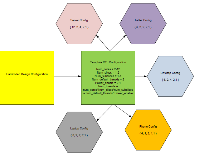
Parameterization is the process of deciding and defining the parameters necessary for a complete or relevant specification of a design. Most of the legacy designs do start with hard coding the parameters for a design and as requirements press on the usage of the design in various configurations, the design team resorts to parameterize some of the common parameters. Figure 1 talks about the many proliferations of one of the graphics design where it could be targeted to a wide variety of markets.
As mentioned in the section 1, the common form of proving the correctness of the design is running an existing dynamic regression over a selected set of seeds and number, just to guarantee that the design has not been compromised on the legacy behavior. But Validation is never complete and comprehensive and there were some corner cases which are always exposed by just running the DV. An obvious verification for this kind of problem is to run FV on the design with the non-parameterized code as Specification model (SPEC) and the parameterized code with the default parameters as the implementation model (IMP).
A positive validation for the base parameters against a non- parameterized code is only possible with such equivalence. For the other valid parameter settings, other dynamic / formal validation techniques would be needed to assess the correct programming. One interesting scenario was observed when a negative formal equivalence was tried with a non-default parameter setting. This kind of equivalency check could be handled by CEC and SEC tools.
2.2 Timing Fixes - Logic Redistribution
Fixing Critical timing paths is one of the common activities
for any synchronous design. One of the common solutions
for fixing critical paths is to redistribute the logic across the
different pipeline stages after resorting to all optimizations[10].
Studies suggest that a decent amount of unintentional functional bugs are
introduced while fixing the timing issues. These kinds of failure scenarios could be
easily avoided by running formal verification making sure the
design retains its sanity irrespective of the logic
redistribution across pipelines.
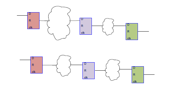
As shown in Figure 2, there is a huge combinational path in between the first and second flops which would be redistributed to fix the violation. In this kind of case, a combinational equivalence checker would fail, as the states would not match across the designs and the sequential equivalence checker is the appropriate solution.
2.3 Timing Fixes - Critical Path Reduction
Where certain timing fixes would not have the flexibility to
redistribute the logic across pipe stages, the designers
bifurcate the computation logic and redirect some of the
computation logic through a parallel flop path as shown in
Figure 3.
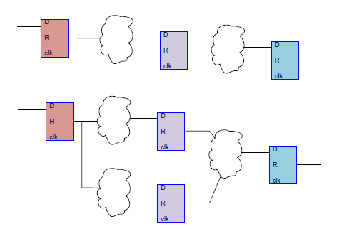
As there is a new parallel pipeline path, this would not be a straight forward problem for the combinational checker to solve. Some tools allow skipping one identified stage of checking but for convergence reasons, mandate the check at the following pipeline stage. While some commercial tools would be intelligently handling these kinds of cases, sometimes, it would need a user intervention for convergence reasons. SEC would be more ideal in these kind of scenarios compared to CEC from proof convergence perspective.
2.4 Pipeline Optimizations
As manufacturing processes, algorithms and implementation methodologies mature over time, computing pipeline depth gets optimized and the functionality could be computed within a reduced pipeline depth. On the contrary, some of the timing fixes and other algorithm requirements may require an addition of extra pipeline stage while retaining the functionality.
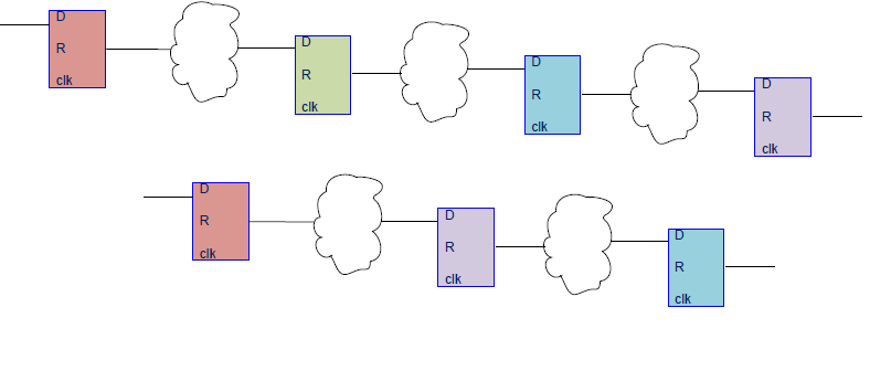
Any of the afore mentioned cases, pipeline optimizations or timing fixes, would need additional states defined in the design. This would need an equivalence check on non-state matching designs. Depending on the case of re-pipelining optimization, one of the above depicted design portion can be considered as SPEC (or the specification/golden reference) and the other IMP (or the implementation/changed design). But the end to end functionality remains unperturbed and hence formal verification would be the ideal solution to guarantee that the functionality is preserved. SEC becomes the methodology of choice for non-state matching design equivalence. The equivalence check would necessitate defining the latencies for both the specification and implementation models.
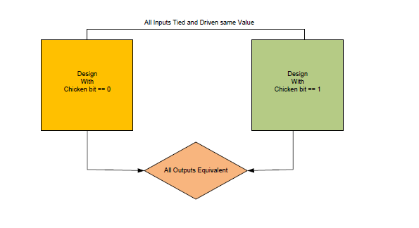
2.5 Chicken Bit Validation
Chicken bits are the bits exposed to the driver to disable a
feature in silicon. It is intended to revert the design changes made where the confidence is not high (confidence is directly
proportional to validation efforts). It is next to impossible
to hit every possible state in pre-silicon through DV. Most of the design
fixes these days do implement chicken bits and many times,
these chicken bits unintentionally affect the real
functionality. Typically most of the critical features account
for chicken bits early in the design cycle. But there would
be a small fraction of the number of chicken bits that are
added towards the end of the design cycle, to give the
flexibility to disable those diffident features. Negative
validation of these kind of chicken bits is
challenging, as a feature disabling is as
intrusive in the code as the feature itself.
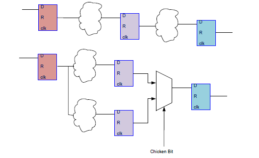
Most of the designs do implement the chicken bit in the mode depicted in Figure 5. One way to guarantee the correctness of the design changes is to run formal equivalence verification of the earlier design against the current design in question with the chicken bit disabled. Though this sort of verification does not need a sequential logic checker, a good debugging capability of the tool used would ease the life of the designer to fix any issues reported.
2.6 Clock gating Verification
One of the most commonly used low-power techniques in any design is clock gating and proper clock gating is necessary for data integrity. If clock is not shut down properly for a piece of logic, improper state signals and signal glitches can propagate and lead to data corruption.
The default verification strategy for a clock-gated design is to run the set of golden regression test suite on both the pre-clock-gated design and the post-clock-gated design, with the assumption that the golden test suite exercises all corner-cases when clocks would be gated. However, this assumption is not always true, especially in less aggressive clock-gating schemes. Coverage of the corner cases is always challenging as the existing suite might not expose all scenarios. The best strategy is to use Sequential Equivalence Checking tools for RTL vs. RTL comparison. CEC might not be an obvious preference for this kind of design check.
As depicted in the Figure 6, FEV is run on a design with clock gating enabled on IMP and disabled in SPEC, to make sure that the design behaves exactly similar in all scenarios. Some of the cases would need addition of realistic constraints on the inputs. These constraints would assist in verifying the real intent and hence assist in convergence.
2.7 Power Aware Equivalence Verification
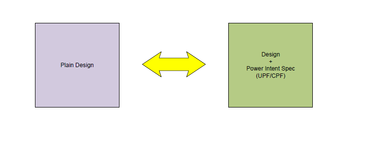
Low power design continues to garner increased attention in nearly every design segment. Many design techniques have been developed to reduce power and by the judicious application of these techniques, systems are tuned for the best power/performance trade-offs. Design sign-off with great quality is essential to avoid re-spins while meeting market pressure. Low power specification defined in UPF (Unified Power Format) introduces certain power-logic such as, insertion of isolation cells or retention mapping during synthesis.
With functional intent being separated from power-intent,
the need for power-aware logical equivalence check (EC)
methodology is indispensable. Formal equivalence of
designs with and without UPF could result in checking if
the power intent (UPF) is syntactically correct and checks
for incorrect/missing/inconsistent isolation rules.
There are various tools available in both CEC and SEC which could handle such equivalence including the power intent. A judicious selection of the tool which can help faster debug and convergence is advised. Any low power tool in industry can do these kind of checks.
2.8 Basic X-Checking: Uninitialized Flops
Almost all designs would have state elements in which
some of them would be initialized to a defined value post
reset and some which are not. Out of reset, these
uninitialized state elements can come out in any state on the
silicon and to represent the same, in simulation, most of the
non-2 valued simulators would bring out those elements as
“X”s. Formal Verification would also bring out those
uninitialized state elements in undefined state which can
take any value of 0/1. All RTL2RTL formal verification
tools provide a utility to define the behavior of all flops
inside the design that are not connected to reset. Our
methodology of checking on those types of Xs by first
initializing those elements to be 0s and make sure the
equivalence test passes, followed by removal of such
constraint which would bring out the Xs emanating from
those flops and the comparison at the output would result in
counter example for the same design used as SPEC and
IMP.
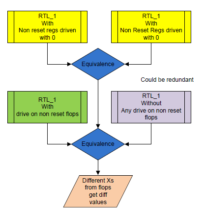
An X emanating from SPEC would not be equal to the X from IMP and hence the counter example would point to the differing state assignment. While deriving the Xs because of the flops, the design could be elaborated where the undriven nets and specific X assignments can be considered as symbolic.
An alternate mode of checking that some flops are driving unwanted values that propagate to the outputs is by assigning all non-resettable state elements to 0 in one design (SPEC) and 1 in the other (IMP). This method of checking is not completely comprehensive, as we might miss some of the critical combinations of 0s and 1s of different state elements. But this mode of checking can converge faster and can catch all the low hanging fruits faster and is useful in bug hunting mode.
2.9 Basic X Checks: Xs from undriven nets or internal assigned Xs or Stopats:
Xs in design can be due to various reasons other than just from the uninitialized state elements. Similar to the above X checking methodology described in section 2.8, the Xs from the direct assignments and the un-driven nets could be derived from the design. The design elaborated with X assumed to be 0/1 and the design elaborated without any such assumption are compared to check for the propogation of Xs.
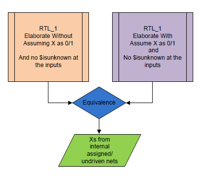
As a prelude to the X checking due to undriven or internal assignments, the tools can be tuned to assume the non-resettable flop elements come out with an equivalent definitive value in both the designs. This methodology would still avoid the checking of X’s due to out of bound array interactions. A tool capable of X-controlling capability can handle this kind of checks. As mentioned in the subsection above, this methodology is very helpful in the bug hunting mode. The constraints are absolutely needed to thwart out Xs being reported from non-functional cases. There had been a lot of cases where we experienced bogus Xs because the inputs are not constrained for the valid set of inputs and hence Xs for those vectors are truly ignorable.
2.10 New Feature Addition with Backward Compatibility
There are certain designs which are very critical to the product, as the operations of those units are exposed to the external customer directly and the design has to stick to some standards of functionality. As an example, the execution unit of the design needs to stick to some standard (IEEE, DX*, OCL, OGL, etc…). The operations handled by the Execution unit will be the instruction set for the design.
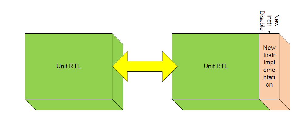
Most of such designs would have reverse compatibility w.r.t the previous generations of the design, which would mean that the instructions which were implemented in the earlier generation would retain the same functionality and the new feature or the instruction implemented should not have tampered with all other features or instructions implemented. This is not applicable to optimizations or changes in the specified behavior of the previous instructions/features.
Most of our new feature additions or opcode additions are taken through the reverse compatibility analysis where the inputs are constrained for disabling the new feature/opcode being added and is checked against the legacy design. This has helped us in maintaining the legacy behavior in spite of new optimization/feature/opcode additions.
2.11 Replacing a Big Data regression with FEV
Most of the data path operations are taken through STE [7]
regression for the implemented proofs at Intel®. Proving
each and every operation for every model would take
anywhere between 3-5 days based on the net batch resource
availability and machine configuration.
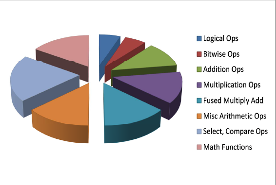
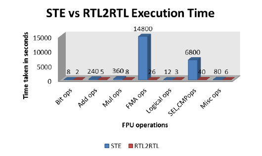
With the advent of powerful equivalence tools, one of the optimization made in the recent times is to run the regression against the previous STE proven implementation. In order to assist in faster convergence, the operations are subdivided into different buckets and the whole regression completes in less than 1 hour on one machine. Comparatively, the complete STE regression used to take 10 machines and decent memory on these resources. The figure 11 depicts the percentage of the time taken by different sets of operations in the whole regression time.
2.12 Regular FPV
One of the most popular techniques in formal property verification is to write out an abstract model of the design similar to RTL and write properties to define the equivalence of the two design outputs. The same methodology can be easily verified through equivalence where the specification is the abstract model and implementation is the real piece of code in the RTL. The regular model checking engines are not as optimized as the equivalence tool engines and the convergence of such checks had always been challenging. Most of such abstract models written might not match the states with the real implemented design and hence the CEC wouldn’t be an ideal choice for such comparison.
3 Complexity Reduction Techniques
Like any formal verification, RTL2RTL FEV also has capacity limitations. A range of techniques are applied to overcome the capacity issues. This section discusses in detail about such techniques used to solve the complexity of the FV task.
3.1 Divide and Conquer Approach
To overcome the capacity issue, typically FV is handled using a divide and conquer approach, similar to the compositional verification [6]. A typical compositional approach would be to decompose the whole problem into number of sub proof tasks and prove each of them independently and rework at the top level with these sub blocks black boxed.
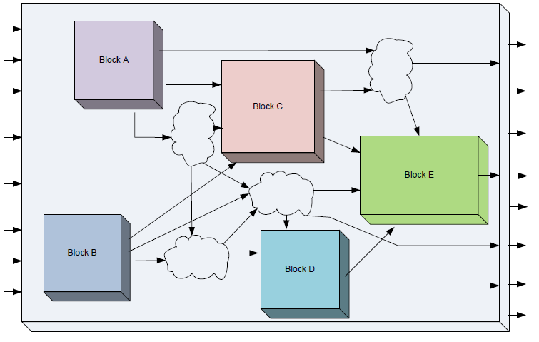
A representative design for discussion is depicted in Figure 12. There are 5 blocks {A-E} with associated logic which represent the complete functionality of the design.
When these independent blocks are of decent size, a complete conglomeration of these blocks would be of a size which crosses a typical limit of the tool handling capacity. With an RTL2RTL FEV, the total design size is twice the size of one design and hence the complexity gets even more cumbersome. Hence, we resort to first proving the largest independent blocks or a set of blocks first, for example A and B blocks separately and then black box them in the design when we do the top level equivalence.
3.2 Selective Enabling and Careful Carving the Logic
Some of the changes in the design would be very limited to
a set of blocks and hence would not necessarily mandate a
complete block level equivalence. We selectively enable certain blocks and black box the
remaining unwanted logic. As the inputs to those block
boxes would be considered as outputs and the outputs of
those blocks would be considered as inputs, we would need
to have those kinds of tools or methodologies to
automatically map those black boxes and the respective
signals. Careful attention has to be taken while choosing
the logic that has to be black boxed making sure that we
don’t accidentally turn off certain blocks where the changes
might be influential.
Not all the times, the design changes are limited to one or
two blocks individually, but do span across those blocks
and hence individual equivalence is not always the
preferred solution. Proper care needs to be exercised in carving out the necessary logic for the equivalence.
3.3 Appropriate Input Constraints or Pruning:
The design would have certain definitive functionality in case of a set of valid input constraints. It usually helps if appropriate prunings are applied on the design so that the input space is constrained and valid. Though the argument is valid that the design should behave similar in case of invalid inputs, it does not really add much value to the validation in question at the cost of increased complexity.
3.4 Case splitting:
Even after pruning the design, the complexity would not have been completely controlled and needs additional methods to converge the design. One of the best known methods is to split the probable inputs into different subsets. An example for the same sort of case splitting is discussed in section 2.11.
3.5 Helper Assertions:
One other technique of controlling the complexity is to pick an intermediate point in both the designs and prove the equality of such point. Once such a point is identified and proven, we can use that as a helper assertion and prove the downstream logic. Effectively the cone of influence (COI) is subdivided into a simpler cone and a bigger portion of the cone can converge at a faster pace. More such helper assertions or equivalence points can help in much faster convergence.
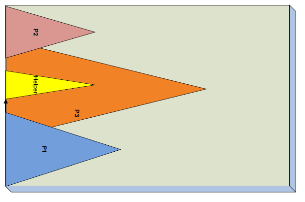
Figure 13 explains the case where there are certain points P1, P2 and P3, where P3 is hard to converge, the equivalence point in both the designs would reduce the cone for the convergence which is depicted by the helper cone and that could help in proving P3 faster.
3.6 State Splitting:
In cases where it becomes a little bit involved in finding an
exact equivalent point, a routine could be written to
selectively equate certain intermediate points (state
matching) and first prove those. If those intermediate points
fail in the equivalence, remove the mappings of those
points and use those particular points which are proven in
both the designs as the helpers and try to converge to the
final outputs. This kind of state splitting is very helpful in
the cases of timing fixes where certain logic is redistributed
across pipeline stages and the design size is huge and
convergence is an issue.
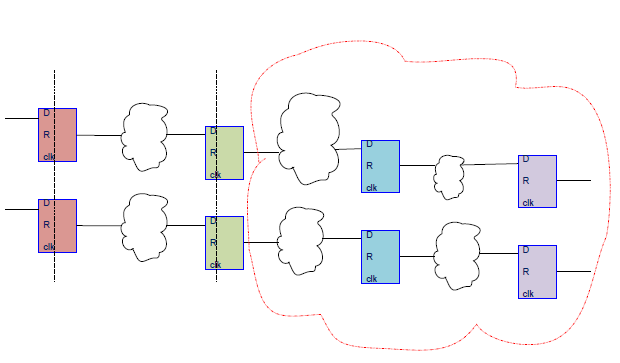
Figure 14 depicts one such case of automatic state splitting where the first two flop stages could be proved first and the logic shown in the red structure would be allowed to be proven by the checker. This way the convergence becomes much faster and cleaner. There are indeed some cases where we deployed scripts to first map all the flops across the design between SPEC and IMP and selectively removed those failing state elements from the mapping and ran it iteratively. Our modus operandi for this kind of logic is to first enable the script and check for the equivalence by brute force method. We also proved the cover points for those points which should definitely be different and convince ourselves that we indeed have exercised the logic. Design knowledge is mandatory to do a diligent equivalence check in some of these involved cases.
3.7 Abstracting the design as applicable
One of the most common form of convergence in the Bounded Model Checking (BMC) form of FPV is to abstract some of the complex structures like FIFOs, Counters, RAMs and memory elements. Some tools do provide methodologies to easily abstract some of these hard to crack nuts and help in faster convergence when such logic could not be completely avoided or black boxed for proving the equivalence.
4 Potential Areas of further Application
4.1 HLS Model Equivalence:
HLS is now an established methodology to synthesize the RTL from a high level language specification like C/SystemC. Some of the designs don’t start with the regular high level model to start with, but take some base from the existing design and recode the same in high level language and take it through HLS and continue coding in the high level, down further. Another form of usage would be to equate the generated RTL against the base with which the high level coding is started. Though this works seamlessly for smaller blocks, working on bigger blocks is still a challenge not yet solved by the current tool set.
5 Results and Conclusion
The RTL2RTL formal equivalence verification has been very successful with its implementation in various flavors at Intel®. The beauty of this technique is that it would not need a bigger validation environment setup or complex assertions to be coded like the regular FPV. The debug also would be much simpler as the spec is one of the standard codes which were verified earlier through different means.
New additions to the code should not change the existing status of the health of the model and that could be easily guaranteed by deploying the formal equivalence for every model release of the design. A great amount of net batch, memory and human resources can be saved by diligent use of the methodology proposed.
There were many cases where the regression time was drastically cut down using the equivalence verification. Figure11 depicts a sample of multiple units taken through FEV against the sanity DV regression, where in the FEV could guarantee 100% confidence in the verification, while the DV failed to give any representative number for the same. There were many instances where the DV passed but the FV would catch such kind of corner cases which was not being exposed in the sanity check in regression. Some of these would have been found in the weekly regression over many more thousands of seeds, but all such effort was clearly saved by deploying FEV for all the cases discussed in the paper.
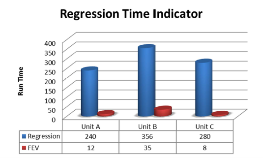
Figure 15 shows the time spent on a sanity DV regression which was effectively saved by deploying an formal equivalence flow for the design changes while guaranteeing 100% coverage of all scenarios. Figure 16 talks about one specific case of STE formal sanity regression replaced with the RTL2RTL formal equivalence based on an earlier proven model.
Compared to all the other forms of formal verification, the equivalence verification is one of the easiest forms and lowers the barrier for any designer or validator who is not an FV expert or exposed to formal methods. We have deployed several scripts and methodologies which help the designers use the RTL2RTL Formal Equivalence as their first line of defense to release the code to the model.
The tools have matured over the time and still striving to enhance their convergence features. We strongly believe that many such enhancements would make the adoption of this methodology much easier assisting in faster design convergence.
ACKNOWLEDGMENTS
Sincere thanks to Archana Vijaykumar who has been
supporting us strong in the activity and enabling us to try
out on various designs. We would also like to thank our design team members for the constant
support provided.
References
- [1]
- [2] Robert K. Brayton, Gary D. Hachtel & Alberto L. Sangiovanni-Vincentelli (1990): Multilevel logic Synthesis. Proceedings of the IEEE 78(2), pp. 264–300, 10.1109/5.52213.
- [3] Orly Cohen, Moran Gordon, Michael Lifshits, Alexander Nadel & Vadim Ryvchin (2010): Designers Work Less with Quality Formal Equivalence Checking. In: DVCon, ACM.
- [4] C. A. J. van Eijk (1998): Sequential Equivalence Checking without State Space Traversal. In: DATE, IEEE Computer Society, pp. 618–623, 10.1109/Date.1998.655922.
- [5] Evgueni I. Goldberg, Mukul R. Prasad & Robert K. Brayton (2001): Using SAT for Combinational Equivalence Checking. In: DATE, pp. 114–121, 10.1145/367072.367111.
- [6] Zurab Khasidashvili, Marcelo Skaba, Daher Kaiss & Ziyad Hanna (2004): Theoretical framework for compositional sequential hardware equivalence verification in presence of design constraints. In: ICCAD, IEEE Computer Society / ACM, pp. 58–65, 10.1145/1112239.1112255.
- [7] V. M. Achutha KiranKumar, Aarti Gupta & Rajnish Ghughal (2012): Symbolic Trajectory Evaluation: The primary validation Vehicle for next generation Intel® Processor Graphics FPU. In: FMCAD, IEEE, pp. 149–156. Available at http://ieeexplore.ieee.org/xpl/articleDetails.jsp?arnumber=64%62567.
- [8] Carlos Ivan Castro Marquez, Marius Strum & Wang Jiang Chau (2013): Formal equivalence checking between high-level and RTL hardware designs. In: LATW, IEEE, pp. 1–6, 10.1109/LATW.2013.6562666.
- [9] Alan Mishchenko, Satrajit Chatterjee, Robert K. Brayton & Niklas Eén (2006): Improvements to combinational equivalence checking. In: ICCAD, ACM, pp. 836–843, 10.1145/1233501.1233679.
- [10] Marios C. Papaefthymiou & Kumar N. Lalgudi (1996): Fixed-phase retiming for low power design. In: ISLPED, IEEE, pp. 259–264, 10.1145/252493.252615.
- [11] Carl Pixley (1992): A theory and implementation of sequential hardware equivalence. IEEE Trans. on CAD of Integrated Circuits and Systems 11(12), pp. 1469–1478, 10.1109/43.180261.
- [12] Sherief Reda & A. Salem (2001): Combinational equivalence checking using Boolean satisfiability and binary decision diagrams. In: DATE, pp. 122–126, 10.1145/367072.367113.
- [13] Nikhil Sharma, Gagan Hasteer & Venkat Krishnaswamy (2006): Sequential Equivalence Checking for RTL models. EETimes Now. Available at http://www.eetimes.com/document.asp?doc_id=1271433.