Simulation of the BESIII Endcap Time of Flight Upgrade
Abstract
The results of a full simulation of an endcap time of flight detector upgrade based on multigap resistive plate chambers for the BESIII experiment are presented. The simulation and reconstruction software is based on Geant4 and has been implemented into the BESIII Offline Software System. The results of the simulations are compared with beam test results and it is shown that a total time resolution of about 80 ps can be achieved allowing for a pion and kaon separation up to momenta of 1.4 GeV/c at a 95% confidence level.
1 Introduction
To enhance the capability of particle identification, it is planned to replace the actual endcap time of flight (ToF) system of the Beijing Electron Spectrometer III (BESIII)
experiment by a system based on multigap resistive plate chambers in summer 2015. MRPCs are gas based avalanche detectors and are already used in various
high energy physics experiments [1, 2, 3]. They are characterized by a high time resolution and a large detection efficiency and can be produced
at low cost with a high granularity [4, 5]. Details about the MRPC’s operational principle are given in [6, 7].
This paper presents the simulation and reconstruction software developed for the MRPC upgrade at the BESIII experiment. The software is implemented into the BESIII Offline Software System (BOSS) [8], capable
to perform a full simulation and reconstruction of the BESIII detector. Besides a comparison of the simulated results with the data taken during a beam test [9],
the enhanced capability of pion and kaon separation in the upgraded BESIII detector is investigated.
2 BESIII Experiment
The BESIII experiment [10] is operated at the Beijing Electron Positron Collider II (BEPCII) at the Institute of High Energy Physics (IHEP). The symmetric experiment covers the center-of-mass energy range from 1.8 GeV to 4.6 GeV and is optimized for the investigation of and charm physics. The double ring collider is designed for a peak luminosity of at beam currents of 0.93 A at GeV.
The detector consists of 5 major components:
(1) The innermost component is a helium gas based Main Drift Chamber (MDC) with 43 layers in total, a single wire spatial resolution of 135 micron and an
angular acceptance of about 93% of 4. The resolution is better than 6% and the momentum resolution for charged particles
with momenta of 1.5 GeV/c in a 1 Tesla magnetic field is 0.5%.
(2) The next outer detector is a ToF system used for particle identification. It is composed of a two-layer-structure of 2300 mm long BC-408 plastic scintillators in the barrel region
(, with being the polar angle) and of a one-layer-structure made of trapezoidal shaped BC-404 scintillators with a height of 480 mm in the endcap regions ().
The time resolution for Bhabha scattering events was measured to be 78 ps in the barrel region, but only about 150 ps in the endcap region [11]. The worse resolution in the endcaps
is mainly caused by multiple scattering interactions in the endcap plate of the MDC and material located between MDC and endcap ToF systems, such as electronics and cables [12].
The resolution for pions and kaons in the endcaps is about 135 ps and thus
allowing for a pion/kaon separation up to momenta of about 1 GeV/c [11].
(3) The Electromagnetic Calorimeter (EMC) surrounds the MDC and ToF systems and consists of 6240 thallium doped cesium-iodide crystals. It provides an energy resolution of 2.5% (5.0%) and a
position resolution of 6 mm (9 mm) for photons with an energy of 1 GeV in the barrel (endcap) parts.
(4) The three inner detector systems are surrounded by a superconducting solenoid magnet, which provides an axial uniform magnetic field of 1.0 Tesla.
(5) The outermost detector is a muon chamber system, which is embedded in the flux return of the magnet. It consists of 8 (9) layers of Resistive Plate Chambers (RPC) in the barrel (endcap) region
and provides a spatial resolution of 2 cm.
3 Endcap ToF Upgrade
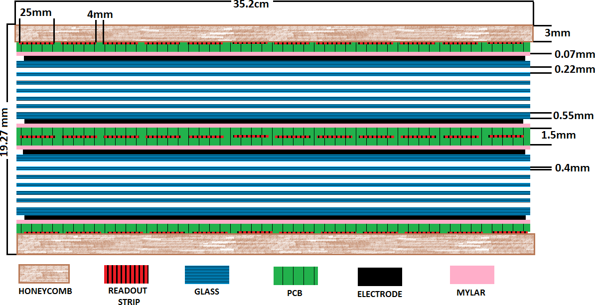
The MRPC modules planned to be used for the endcap ToF upgrade at the BESIII detector are double stack MRPCs
with in total 12 gas layers with a thickness of 0.22 mm, separated by 0.4 mm thick glass plates. The glass plates covering the electrodes have a thickness of 0.55 mm.
The electrodes are separated by 0.07 mm thick mylar layers from the printed circuit board containing the readout strips with a characteristic impedance of less than 50 .
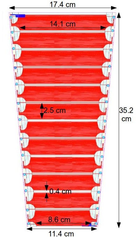
The module is covered with a honeycomb structure on both sides for protection against damages. Figure 1 shows a sketch of a MRPC module and a top view
and the dimensions of the readout strips.
The modules will be operated at a voltage of about 14 kV (corresponding to an electric field strength of about 106 kV/cm)
with a gas mixture of 90% C2F4H2 (Freon), 5% SF6 and 5% iso-butane. Each module will contain 12 readout strips, which are read out on both sides. Thus, the differences
in the arrival time of the signals can be used to reconstruct a one-dimensional impact position of a particle.
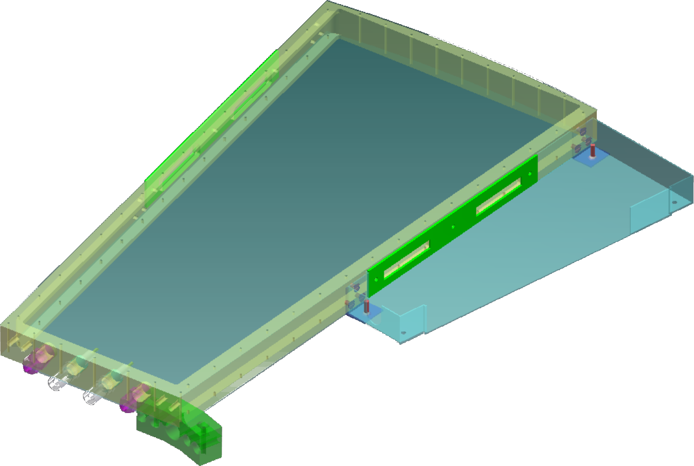
The modules will be placed in a 25 mm thick aluminum frame on one side of which an additional box is mounted containing the front-end electronics (FEE) (figure 1).
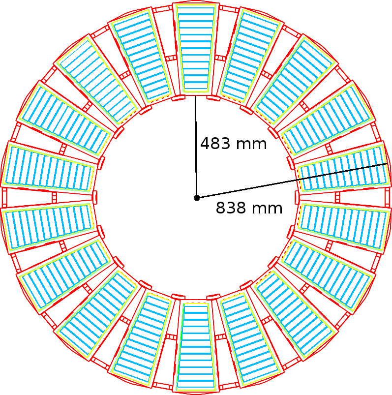
To overcome the dead area arising due to the additional box for the FEE and the dead area at the borders of a single module, each endcap will consist of two layers of modules, which are shifted towards each other.
A single layer will contain 18 modules arranged in a ring (figure 1) and will thus have 432 readout channels, which are read out by NINO chips [13].
The rising edge of the NINO chip’s signal encodes the time measurement and the length of the pulse (time over threshold) encodes the charge induced in the readout strips. The signals produced by
the NINO chips will be fed into high performance time-to-digital converters [14] providing a time resolution of 25 ps.
4 Simulation
The geometric and material properties of the MRPC detector upgrade are implemented into BOSS [8] by means of Geant4’s concept of logical and physical volumes [15]. The Geant4 physics list used for the simulations is the standard list QGSP_BERT_CHIPS.
The signal electron multiplication in the simulation is described using statistical language. Detailed information about electron multiplication in gases at high electric fields can be found in [16], whereas here only a brief introduction is given. Starting with a single electron at the probability of having electrons at can be calculated (in first order) according to
| (1) |
with , , the Townsend coefficient and the attachment coefficient [16]. Equation 1
can only be employed for and , which holds for the operation of a MRPC in a high electric field.
The simulation of the electron avalanche is based on the 1D-model introduced by Riegler, Lippmann and Veenhof [17]: At the beginning each gas layer of the detector is divided into steps of size
and the primary electron-ion pairs are distributed along the gap according to the information provided by Geant4. For each single electron, the number of electrons at
a distance is calculated according to the probability
distribution of equation 1. The latter step is repeated until all electrons have left the gap.
To speed up the simulation process, for sufficiently large numbers of electrons () the central limit theorem is applied. The number of electrons in the next step is simply calculated by drawing a
random number from a Gaussian distribution with mean and standard deviation with [18].
However, this simple model has a serious drawback as it does not consider space charge effects and thus results in a steady growth of the avalanche charge, which is not observed in experiments. To take into account
space charge effects a simple cut-off is applied [19]. The avalanche is saturated and does not grow anymore as soon as the number of charge carriers exceeds .
This simple cut-off does not affect the main characteristics of the MRPC, such as efficiency and resolution, as they are only sensitive to the first stage of the avalanche [20].
The current induced in the readout strips by the moving charge carriers is calculated utilizing Ramo’s theorem [21], with being the drift velocity and the charge of
the charge carriers. is the electric weighting field [18] and the number of charge carriers at a certain time .
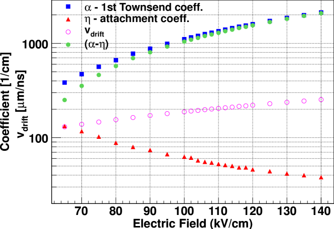
The Townsend coefficient , the attachment coefficient and the drift velocity of the charge carriers are required to perform the electron multiplication and to determine
the induced current in the readout strips. These parameters are not provided by Geant4 and thus are calculated with MAGBOLTZ [22]. The results for the gas mixture of 90% C2F4H2 (Freon),
5% SF6 and 5% iso-butane at standard conditions for pressure and temperature for different electric fields strengths are shown in figure 2.
The average energy deposition required to produce an ionization (an electron-ion pair) in the gas mixture is also required at simulation level by Geant4. It was set to 40 eV for all simulations.
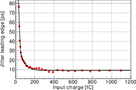
Uncertainties in the time domain arising from the avalanche process due to fluctuations in the electron multiplication are covered by the model and are about 25 ps for the signal from all 12 gaps at an electric field strength of 110 kV/cm. Further uncertainties in the time measurement arise from the TDC resolution (25 ps), the jitter of the leading edge of the NINO chips, which depends on the input charge (figure 3), and additional components (such as cable or noise) chosen empirically to be ps. These components are considered by smearing the measured time value with a Gaussian distribution with the corresponding standard deviation .
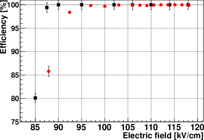
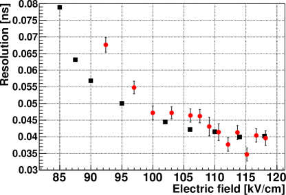
Figure 4 shows a comparison of simulated and measured efficiencies and time resolutions for different electric field strengths. The measured results are from
a MRPC prototype test at the BEPCII E3 beam line with protons with a momentum of about 600 MeV/c [9]. The threshold for signal detection was set to a charge induction of
70 fC for a readout strip.
The simulated data agrees well with the measurements for a field strength larger than 100 kV/cm. For a field strength smaller than this value the time resolution is underestimated in the simulation.
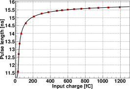
The input charge simulated in the model is converted into the time over threshold measurement of the NINO chip by a function relating the input charge to the time over threshold measurement.
The resulting converted pulse length has been then smeared with a Gaussian with a standard deviation of 0.3 ns, corresponding to an uncertainty of about 2% within the conversion.
The function to relate input charge and time over threshold has been generated
with a pulser (figure 3).
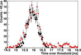
The result of the simulation is shown in figure 3 and fits the measured time over threshold spectra well, except for values larger than 17 ns.
This part of the spectra may arise from streamers, which are not covered by the avalanche simulation in the underlying model.
5 Reconstruction
The reconstruction software is also embedded into BOSS and its tasks are to match the tracks reconstructed in the MDC with the corresponding MRPC signals, to apply walk corrections and to correct for effects from electronics and cable delays, and to determine the transition time of the signals within the readout strips, which is required to improve the measured time information.
To match the reconstructed MDC tracks with the MRPC signals, the tracks are extrapolated to the outer sub-detector systems by means of a Geant4 based tracking and stepping algorithm, which considers
magnetic deflection and ionization energy loss [8].
Around the extrapolated impact position on the MRPC detector (which are all readout strips of the MRPC module the extrapolated track is pointing to
and the readout strips of the directly adjacent MRPC modules) a search is done for signals caused by the corresponding MDC track. If two or more candidates exist, the strip with the largest charge deposition is chosen.
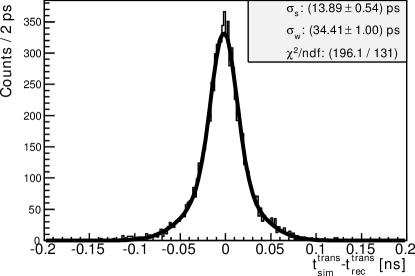
The transition time of the signal within the readout strip is reconstructed using the impact position of the extrapolated MDC track. Figure 6 shows the difference of the simulated and
reconstructed transition time and has been fitted with a double Gaussian. The standard deviation of the first Gaussian (covering 87% of the signals) is 14 ps (corresponding to a position resolution
of about 0.4 cm), whereas the standard deviation of the second Gaussian is 34 ps. An explanation of the origin of the two different Gaussian components
can not be given yet, but it may be related to the Geant4 based algorithm, which is used to extrapolate the impact position on the readout strip. If the extrapolated MDC track does not point to a readout strip which has caused the signal
(for example the MDC track is extrapolated to a strip, which does not have the largest charge deposition, but the neighbouring strip), the impact position (transition time) is calculated using the different
time of arrival of the signal on both sides of the readout strip. Here the achieved resolution is about 38 ps.
6 Improvement in Pion and Kaon Separation
One of the major tasks of the ToF system at the BESIII detector is to allow for the separation of pions and kaons with momenta larger than about 600 MeV/c
(starting from this momentum the difference in specific ionization energy loss of the particles can not be used anymore for their clear separation [24]).
To study the improvement in pion and kaon separation, single particle events of pions and kaons with momenta between 0.5 GeV/c and 1.5 GeV/c have been simulated and fully
reconstructed using the current ToF system and the upgraded ToF system in BOSS. The pion and kaon separation power can be expressed as
| (2) |
with being the fitted difference of measured time of flight and expected time of flight and the corresponding width of the Gaussian distribution. A separation power of corresponds to a misidentification probability of 7.9%, a separation at 95% confidence level to . The expected time of flight can be calculated according to
| (3) |
with being the relativistic velocity of the particle, the velocity of light, the momentum of the particle measured in the MDC and the mass of the particle.
is the distance traveled by the particle (extrapolated track length), which has been determined by a separate reconstruction algorithm.
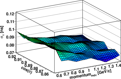
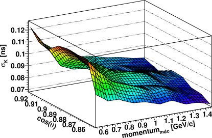
Using the simulated data the distributions and have been fitted with a Gaussian for different momentum intervals
and the separation power has been calculated. The width of the distributions and is shown in figure 5 for different
momenta and values. rises for smaller momenta, as the resolution of the algorithm determining the track length worsens.
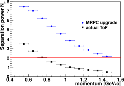
The separation power for different momenta of the current ToF system and the upgraded one is shown in figure 6.
The improvement using the MRPC based version is clearly visible. The upgraded system will allow for a pion and kaon separation up to momenta of 1.4 GeV/c at a 95% confidence level.
7 Summary and Conclusions
The endcap ToF system of the BESIII experiment is planned to be upgraded using nowadays available MRPC technology in summer 2015.
The implemented model for detector simulation is able to reproduce the beam test results and is fully implemented into the software framework
of the BESIII experiment. The reconstruction software is also embedded into the framework and allows for matching reconstructed
MDC tracks with the measurements of the MRPC system. The impact position reconstruction allows for a correction of the time measurement
and so for reducing uncertainties arising due to the size of the readout strips.
The results of the full simulation and reconstruction show that a significantly improved pion and kaon identification at 95% confidence level up to momenta of 1.4 GeV/c can be achieved.
References
- [1] H. Pol, et al., A large area timing RPC prototype for ion collisions in the HADES spectrometer, Nucl. Instr. and Meth. A 535 (1–2) (2004) 277 – 282.
- [2] P. Cortese, et al.ALICE: Addendum to the technical design report of the time of flight system (TOF).
- [3] Y. Sun, et al., New prototype multi-gap resistive plate chambers with long strips, Nucl. Instr. and Meth. A 593 (3) (2008) 307 – 313.
- [4] P. Fonte, R. F. Marques, J. Pinhao, N. Carolino, A. Policarpo, High-resolution RPCs for large TOF systems, Nucl. Instr. and Meth. A 449 (1–2) (2000) 295 – 301.
- [5] A. Akindinov, et al., Data quality monitor as the final quality assurance procedure for the ALICE-TOF detector, Nucl. Instr. and Meth. A 602 (3) (2009) 821 – 824.
- [6] M. Williams, The development of the multigap resistive plate chamber, Nuclear Physics B - Proceedings Supplements 61 (1002) (1998) 250–257.
- [7] E. C. Zeballos, et al., A new type of resistive plate chamber: The multigap RPC, Nucl. Instr. and Meth. A 374 (1) (1996) 132 – 135.
- [8] Weidong Li, Yajun Mao and Yifang Wang, The BESIII Detector and Offline Software, International Journal of Modern Physics A 24 (1) (2009) 9–21.
- [9] S. Yang, et al., Test of High Time Resolution MRPC with Different Readout Modes for the BESIII upgrade, accepted by Nucl. Instr. and Meth. AarXiv:arXiv:1405.2115[physics.ins-det].
- [10] M. Ablikim, et al., Design and Construction of the BESIII Detector, Nucl. Instr. and Meth. A 614 (2010) 345–399. doi:10.1016/j.nima.2009.12.050.
- [11] C. Zhao, et al., Time calibration for the end cap TOF system of BESIII, Chinese Physics C 35 (1) (2011) 72.
- [12] Z. Hui, et al., A GEANT4 simulation study of BESIII endcap TOF upgrade, Chinese Physics C 37 (9) (2013) 096002.
- [13] F. Anghinolfi, et al., NINO: An ultra-fast and low-power front-end amplifier/discriminator ASIC designed for the multigap resistive plate chamber , Nucl. Instr. and Meth. A 533 (1–2) (2004) 183 – 187.
- [14] M. Mota, J. Christiansen, S. Debieux, V. Ryjov, P. Moreira, A. Marchioro, A flexible multi-channel high-resolution time-to-digital converter asic, in: Nuclear Science Symposium Conference Record, 2000 IEEE, Vol. 2, 2000, pp. 9/155–9/159 vol.2.
- [15] S. Agostinelli, et al., Geant4 – a simulation toolkit, Nucl. Instr. and Meth. A 506 (3) (2003) 250 – 303.
- [16] W. Legler, Die Statistik der Elektronenlawinen in elektronegativen Gasen, bei hohen Feldstärken und bei großer Gasverstärkung, Z. Naturforschg. 16a (1961) 253 – 261.
- [17] W. Riegler, C. Lippmann, R. Veenhof, Detector physics and simulation of resistive plate chambers, Nucl. Instr. and Meth. A 500 (1–3) (2003) 144 – 162.
- [18] M. Shao, et al., Simulation study on the operation of a multi-gap resistive plate chamber, Measurement Science and Technology 17 (1) (2006) 123.
- [19] C. Lippmann, W. Riegler, Space charge effects in Resistive Plate Chambers, Nucl. Instr. and Meth. A 517 (1–3) (2004) 54 – 76.
- [20] M. Abbrescia, et al., Progresses in the simulation of Resistive Plate Chambers in avalanche mode, MS Conference Report CMS CR 1998/021.
- [21] S. Ramo, Currents induced in electron motion, Proceedings IRE 27 (1939).
- [22] S. Biagi, Monte Carlo simulation of electron drift and diffusion in counting gases under the influence of electric and magnetic fields, Nucl. Instr. and Meth. A 421 (1–2) (1999) 234 – 240.
- [23] D. Hongliang, Private communication.
- [24] D. Asner, et al., Physics at BESIII, Int. J. Mod. Phys. A24 (2009) S1–794.
- BESIII
- Beijing Electron Spectrometer III
- BEPCII
- Beijing Electron Positron Collider II
- IHEP
- Institute of High Energy Physics
- BOSS
- BESIII Offline Software System
- MDC
- Main Drift Chamber
- ToF
- time of flight
- MRPC
- multigap resistive plate chamber
- EMC
- Electromagnetic Calorimeter
- RPC
- Resistive Plate Chambers
- FEE
- front-end electronics
- HPTDC
- high performance time-to-digital converter