Effect of Beam Dynamics Processes in the Low Energy Ring ThomX††thanks: This work is supported by the French ”Agence Nationale de la Recherche” as part of the program ”investing in the future” under reference ANR-10-EQPX-51. This work was also supported by grants from Région Ile-de-France.
Abstract
As part of the R&D for the 50 MeV ThomX Compton source project, we have studied the effect of several beam dynamics processes on the evolution of the beam in the ring. The processes studied include among others Compton scattering, intrabeam scattering, coherent synchrotron radiation. We have performed extensive simulations of a full injection/extraction cycle (400000 turns). We show how each of these processes degrades the flux of photons produced and how a feedback system contributes to recovering most of the flux.
1 Beam dynamics at ThomX
ThomX [1] will be a 50 MeV compact accelerator used to produce X-rays by Compton scattering between electrons and a laser. It will be made of a linac and a ring in which the beam will be stored for 20 ms. A more detailed description of the project is available elsewhere in these proceedings [2] and in the projet’s TDR [3]. Given the very short storage time, the short bending radius and the low energy of the electrons, several beam dynamics effect will have a strong effect on the expected flux.
An extensive study of the beam dynamics at ThomX has been performed, including among others the effects of Compton backscattering (CBS), intrabeam scattering (IBS) and coherent synchrotron radiation (CSR). This study is described in [4] and we present here its main results.
2 Simulation code
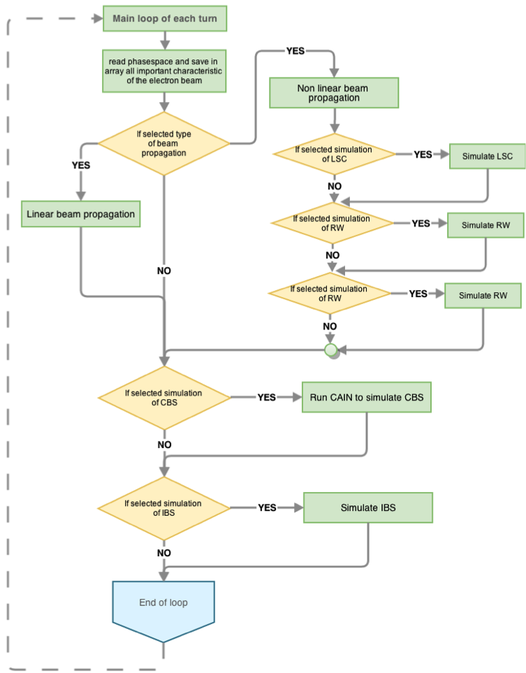
The simulation code we have used is based on Matlab. It is written as a shell in which several beam dynamics effects are implemented with macro-particles beings passed from the simulation of one effect to the other as arrays. The code has also the flexibility of calling external program such as CAIN [5]. The properties of the macro-particles can be exported after each turn although it is advised to do it less often to minimize the disk space used. The structure of the code is shown on figure 1.

 |
 |
 |
 |
 |
 |
The possibility of exporting all macro-particles properties also allows to break the execution of the simulation in several jobs to be executed serially on a computer farm. The duration of the simulation will depend on the number of macro-particles chosen. For macro-particle a simulation of the full injection/extraction cycle will take several week although, as we will see below, this can be significantly shortened if one is mostly interested in what happen during the initial transient period.
3 Initial instabilities due to mismatching
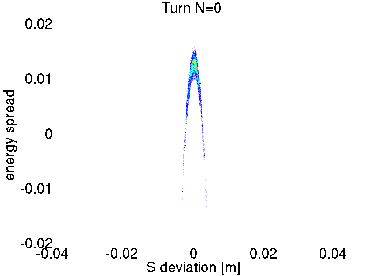
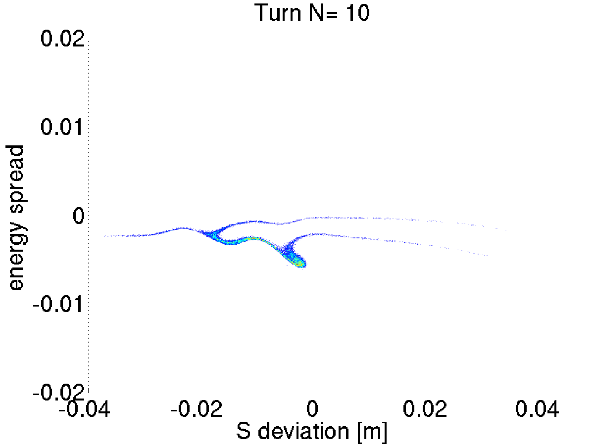
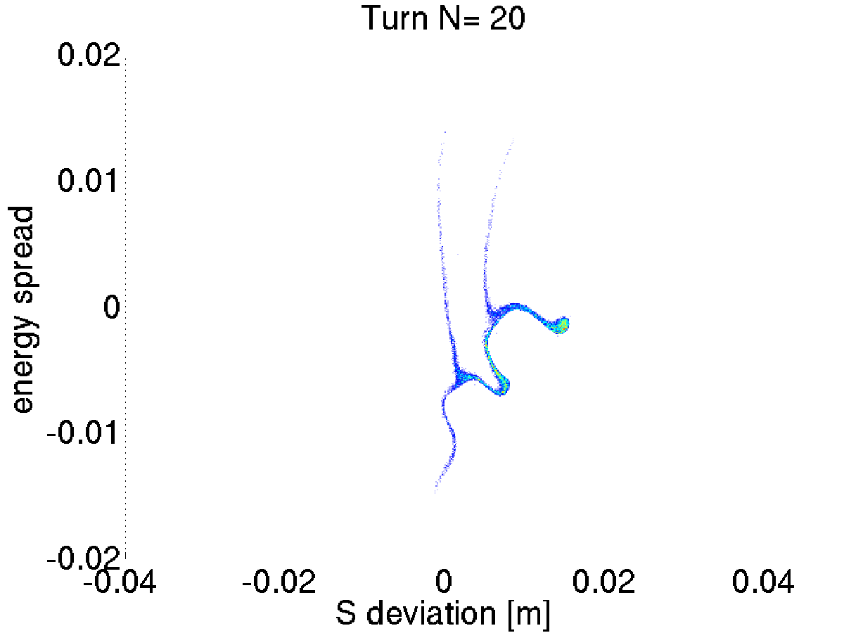
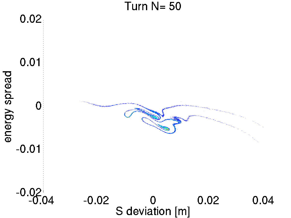
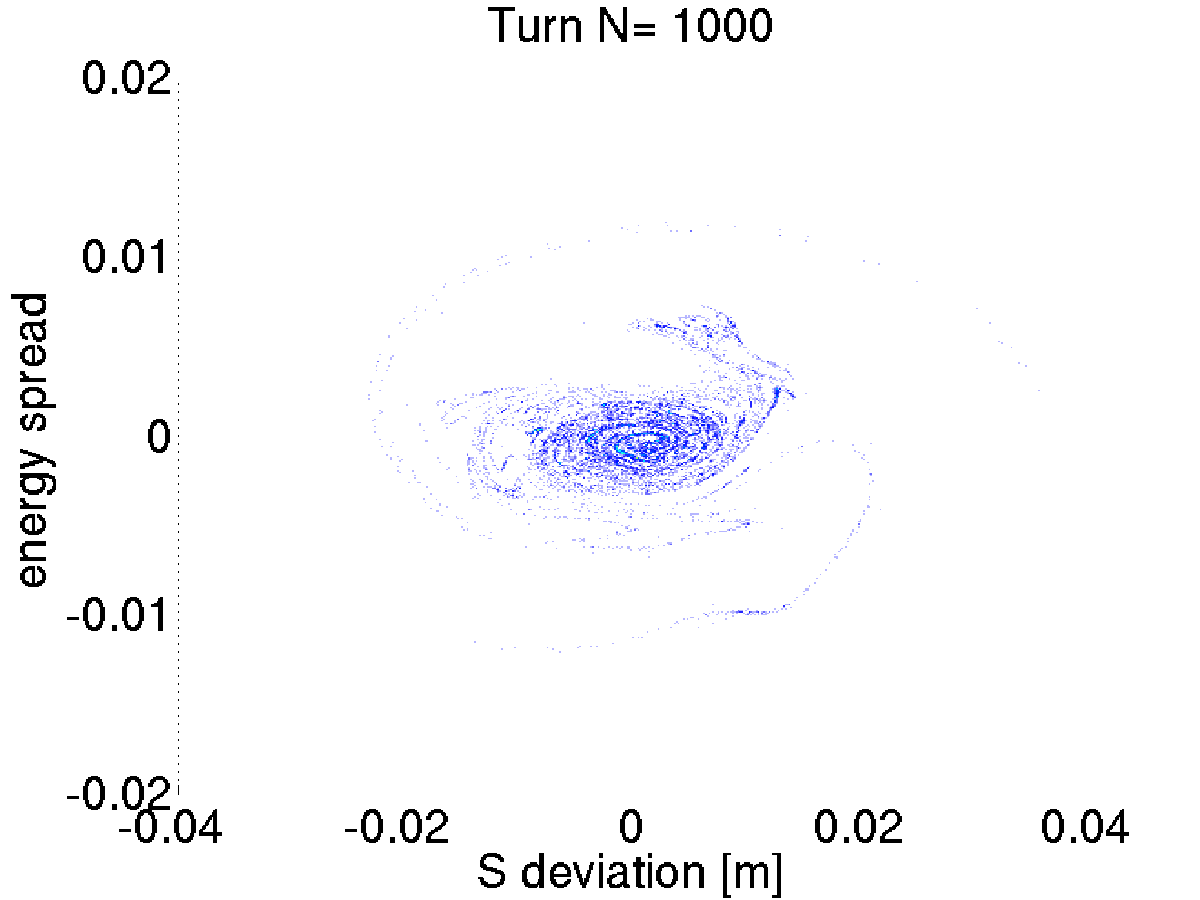
Using the code with have made a full simulation of the evolution of the longitudinal phase space as function of time. As expected and as shown on figure 2 just after injection the beam enters in a turbulent regime. This is due to the shape of the injected beam being mismatched with the shaped of the bucket. During this turbulent regime a fraction of the charge may be lost.
4 Effect of Coherent Synchrotron radiation
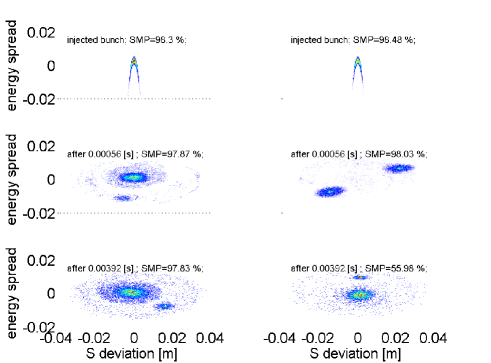
At high charge the most disruptive effect is CSR. While performing our simulations we saw that sometimes CSR can split the bunch in two or more parts leading to a significant fraction of the charge to be ejected from the bunch. This result in a lower X-ray yield. Examples of simulations of the longitudinal phase space with and without such beam break-up are shown on figure 3: for the same initial beam parameters but for different random distributions of the macro particles one case leads to a relatively stable beam whereas the other case leads to the bunch been split in two parts within less than 10 000 turns and one of the two parts is then lost shortly after leave only 56% of the macro particules in the bunch.
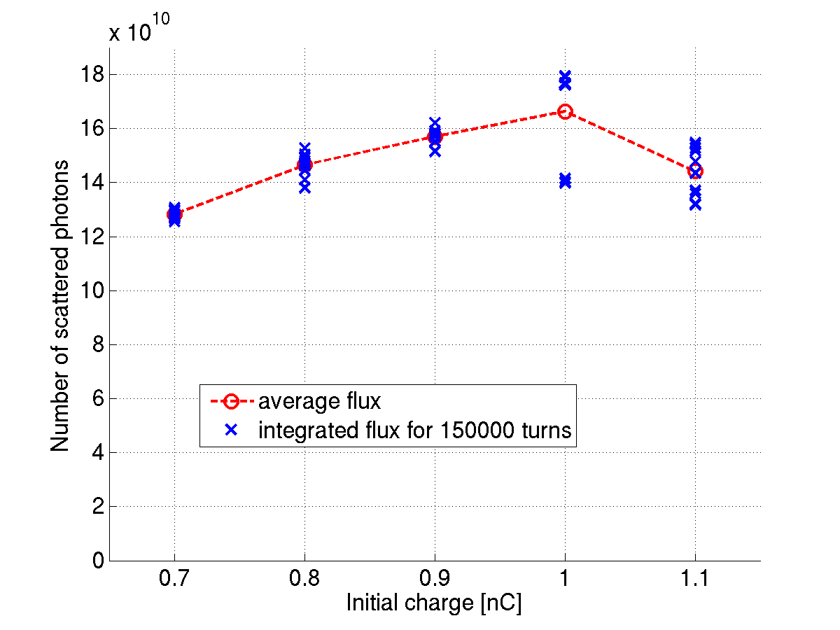
This beam break-up means that there is a threshold above which adding charge at injection will in fact decrease the charge that can actually be stored and therefore decrease the X-ray yield. This is shown on figure 4 where one can see that the average flux produced for an initial charge of 1nC is higher than the flux produced for an initial charge of 1.1nC.
5 Overall flux
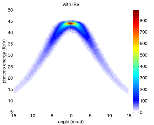
Using the simulation code it is possible to simulate a full storage and predict the spectrum obtained. Fig. 5 shows an example of photons spectrum where the intensity is plotted against the energy (vertical axis) and the scattering angle (horizontal axis).
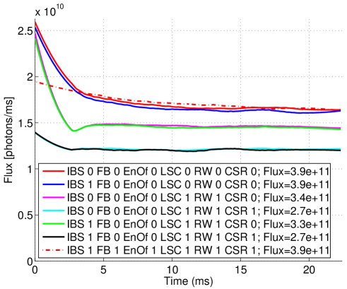
It is also possible to investigate the effect of each beam dynamics effect on the final flux. For that we made several simulations where we turned on or off some effect selectively to see how doing this changed the flux. The result of these simulations is shown on figure 6. Although in reality it will not be possible to turn off effects, understanding what is causing the losses will help us in designing the best possible mitigation strategy.
6 Outlook
We have written a simulation code to study the beam dynamics at the ThomX Compact Light Source. This allows us to better understand how beam dynamics will affect the photon flux with the aim of designing a mitigation strategy. We see that CSR is the effect that will the most significantly decrease the flux and the main reduction in flux will occur during the first 5 ms of the cycle.
References
- [1] Variola et. al. The ThomX project. IPAC, weoaa01, 2011.
- [2] Variola et. al. The ThomX project status. IPAC, 2014.
- [3] Variola et. al. ThomX TDR. LAL/RT 14-21 SOLEIL/SOU-RA-3269, 2014.
- [4] I. Drebot. Electron beam dynamics with and without compton back scattering. Université Paris-Sud, Doctoral Thesis, 2013.
- [5] K. Yokoya T. Tauchi and P. Chen. Cain. Part. Acc., 41(29), 1993.