Photonic spin Hall effect in metasurfaces with rotational symmetry breaking
Abstract
Observation of photonic spin Hall effect (SHE) in dielectric-based metasurfaces with rotational symmetry breaking is presented. We find that the spin-dependent splitting is a unique angular splitting in the real position space, and is attributed to the space-variant Pancharatnam-Berry phase (PB). Breaking the rotational symmetry of the PB phase by misalignment of the central axes of the incident beam and the metasurface, the spin-dependent shift is observable. We show that the spin-dependent shift can be enhanced by increasing the rotation rate of the metasurface, so the metasurface provides a great flexibility in the manipulation of photonic SHE.
pacs:
42.25.-p, 42.79.-e, 41.20.JbI Introduction
In quantum mechanics, spin is an intrinsic angular momentum, which is the inherent nature of elementary particles. Electronic spin Hall effect (SHE) is a transport phenomenon in which an electric field applied to spin particles results in a spin-dependent shift perpendicular to the electric field direction Murakami2003 ; Sinova2004 ; Wunderlich2005 . Photons can be assigned with two opposite spin states with the spin axes parallel and anti-parallel to the wave vector, which correspond to left- and right-circular polarizations, respectively. Photonic SHE, which is generally believed to be a result of topological spin-orbit interaction Hosten2008 ; Bliokh2008I , is just the photonic counterpart of the SHE in electronic system Onoda2004 ; Bliokh2004 ; Bliokh2006 ; Duval2006 . The spin-orbit interaction describes the coupling between the spin (circular polarizations) and orbital degrees of freedom of photons, which is the signature of two types of geometric phases: the Rytov-Vladimirskii-Berry (RVB) phase and the Pancharatnam-Berry (PB) phase. The former is related to the evolution of the propagation direction of light Onoda2004 ; Bliokh2006 ; Hosten2008 and the latter to the manipulation with the polarization state of light Bliokh2008I ; Bliokh2008II .
When a linearly polarized paraxial light beam impinges obliquely upon an interface between two different media, the spin-dependent splitting in real position space generates, which is associated with the RVB phase. This photonic SHE draws considerable attention in recent years due to its potential applications in precision metrology Zhou2012I ; Zhou2012II and spin-based photonics Hosten2008 ; Shitrit2013 . However, the shift induced by the photonic SHE is very tiny, usually with the order of a fraction of the wavelength. Weak measurement is a sensitive method to detect the photonic SHE Hosten2008 ; Qin2009 ; Luo2011 ; Gorodetski2012 , which enlarges the original tiny displacement with preselection and postselection technology. Recently, Yin et. al. demonstrated experimentally a spin-dependent splitting in a thin metasurface with designed in-plane phase discontinuity at the wavelength scale, which is related to the RVB phase Yin2013 . Within their scheme, opposite spin states accumulated at the opposite edge of the beam and constructed a spin-dependent splitting perpendicular to the designed phase gradient.
While for an inhomogeneous anisotropic medium (e.g., liquid crystal q plate), the light beam can acquire the PB phase. The inhomogeneous anisotropic medium is usually be presented with rotational symmetry, which is expected to produce vortex beams or vector beams with great potential in microparticle manipulation and quantum information Bomzon2001 ; Marrucci2006 ; Zhao2013 . With rotational symmetry of the medium, the produced PB phase would also be locally varying and forms a geometric phase gradient in the azimuthal direction. Actually, the PB phase is spin-dependent, that is, the spin of the incident photons determines the sign of the phase. However, if the incident light involves both spin components, these components would always superpose at the corresponding position due to the rotational symmetry, although they should have acquired just opposite PB phase. Breaking the rotational symmetry, it is likely to observe a spin-dependent splitting of light, i.e., photonic SHE, due to the geometric phase gradient. It has been reported in a one-dimensional plasmonic chain, which can be viewed as breaking a rotationally symmetric structure from polar coordinate to the Cartesian coordinate Shitrit2011 . More recently, spin-dependent splitting in metasurfaces has been observed when the spatial inversion symmetry is violated Shitrit2013 . The resulted photonic SHE is large enough for direct measurements, in contrast with the indirect detecting technology using the weak measurement.
In this work, we report the observation of photonic SHE in dielectric-based metasurfaces with rotational symmetry in which we break the rotational symmetry of PB phase by means of misaligning the central axes between the light beam and the metasurfaces. In recent years, metasurfaces is gaining a reputation for introducing a designed geometric phase Shitrit2013 ; Yu2011 ; Kildishev2013 . The metasurfaces applied in this work are fabricated by etching locally varying grooves in a silica glass. As the optical dimension of the grooves is much less than the working wavelength, it creates a metasurface with inhomogeneous anisotropy due to the form birefringence Beresna2011 . It produces a spin-dependent angular splitting of light in the real position space as compared with the parallel splitting related to the RVB phase. Suitably engineering the metasurface geometry, we can achieve any desirable PB phase, and thereby the spin-dependent splitting of light.
II Theoretical model
In order to get insight into the physical mechanism of the metasurface, Jones calculus is performed here to analyze the polarization and phase transformation. The Jones matrix of the metasurface with inhomogeneous local optical axes and constant retardation can be written as Liu2014
| (1) |
where is the local optical axis direction. When a right-circular () or left-circular () polarization beam normally impinges into the metasurface, the output state can be calculated as
| (2) |
| (3) |
where and represent the right- and left-circular polarization, respectively. It is clear that an additional phase factor is induced in this process and its sign is spin-dependent. Deriving from the conversion of polarization states, obviously, this additional phase is the PB phase in nature and depends only on the orientation of local optical axes. As the local optical axes varying with location, the passing beam will obtain a position-dependent PB phase.
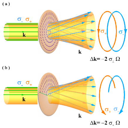
When the metasurface be engineered with rotational symmetry [Fig. 1(a)], the induced PB phase would form a spiral beam wavefront because of the linear rotation of the local optical axes in the azimuthal direction. In this way, both right- and left-circular polarizations (spin states) can acquire a helical phase. For different spin states, the helical phases are opposite, which would bent the wave vectors along the spin-dependent phase gradient as shown in Fig. 1. However, the wave vectors of two spin states still overlap with each other in the real position space, so that there is no spin-dependent splitting in this situation [Fig. 1(a)]. Hence, we manage to keep the tendency of deflection but separate the opposite spin states. It is realized by scrubbing part of the inner structure of metasurface as shown in Fig. 1(b). Removing part of the inner structure will break the rotational symmetry of metasurface so as to make the separation of spin states observable in the real position space.
Note that the geometric phase gradient in the azimuthal direction is proportional to the rotation rate of local optical axes, which is deduced from Eqs. (2) and (3). When we refer to a small part of the metasurface as shown in Fig. 1(b), the phase gradient can be approximately regarded as in the horizontal direction. Thus, the constructed geometric phase gradient can be related to the rotation rate of the metasurface in the form:
| (4) |
where is the incident spin state, denotes the rotation of local optical axes in a unit length , is the induced PB phase.
As this derivation, when we refer to the normal incidence, the emerged beam should be diffracted due to the PB phase gradient along the metasurface. The transmission angle is proportional to the phase gradient in the small-angle approximation:
| (5) |
where is the vacuum wavelength.
According to the Eqs. (4) and (5), we find that the transmission angle should be opposite in sign for different incident spin states. This spin-dependent angle and the spin displacement can be represented by
| (6) |
where . These results show an angular splitting in the real position space. The intensity splitting can be induced after the light propagating to the far field.
It is clear that the photonic SHE usually refers to a transverse spin-dependent splitting, when a spatially confined light is reflected or refracted at an interface. This transverse splitting is generally independent of the propagation distance in real position space. However, the splitting in our scheme is totally different with these ordinary situations. By introducing a spin-dependent PB phase gradient in the metasurface, a spin-dependent angular splitting is demonstrated. The splitting angle is proportional to the phase gradient along the surface, and the spin displacement will increase upon propagation. For an appropriate designed rotation rate, the spin-dependent splitting of intensity would be enhanced for a direct observation.
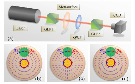
III Experimental observation
We implement an experiment to demonstrate the angular splitting and the photonic SHE [Fig. 2(a)]. A He-Ne laser is applied as the light source. Beam passing through the Glan polarizer impinges into the metasurface. A quarter waveplate and a second polarizer cooperate with the charge couple device (CCD) to record the spin distribution of the output beams. There are three different metasurfaces applied in our experiment, which are schematically demonstrated in Figs. 2(b)-2(d), respectively. The three metasurfaces applied in our experiment are designed with different rotation rates. By etching grooves with appropriate directions and geometrical parameters, we can achieve effective birefringence in the metasurface (Altechna). The nano-grooves in the metasurface with uniform phase retardation can reverse the circular polarizations and introduce the desired PB phase.
When a linearly polarized beam incident upon the metasurface along the central axis, where the incident position is marked by the yellow circles in Figs. 2(b)-2(d), the metasurface applies rotationally symmetric response to the beam as depicted in Fig. 1(a). To break the rotational symmetry and achieve a spin-dependent angular splitting, as shown in Fig. 1(b), we deviate the propagation axis from the center of metasurface [positions marked by green circles in Figs. 2(b)-2(d)]. This scheme is similar to scrubbing part of the inner structure of metasurface. Firstly, we verify that the structure with rotational symmetry can covert a circular polarized plane beam to its opposite circular polarization state with a helical phase.
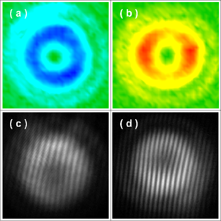
Figure 3 shows the intensity distribution and interference pattern for PB phase of the emerging beam when the metasurface functioned with rotation symmetry. Metasurface corresponding to Fig. 2(b) is selected as the example. The intensity located in a single ring and a characteristic dark spot with zero intensity in the center is a signature for the beam with helical phase [Figs. 3(a)-3(b)]. The helical phase can be confirmed by the interference with a reference beam shows fork dislocation [Figs. 3(c)-3(d)]. By means of local polarization transformation of the metasurface, it is possible to convert a light beam with homogeneous elliptical polarization into a vector beam with any desired polarization distribution in higher-order Poincaré sphere Liu2014 . Whereas, there is no spin-dependent splitting in this evolution.
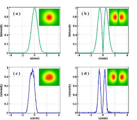
When the input and output states are orthogonal, we look forward to detecting the cross-polarized components, hence, to register the spin-dependent splitting Bliokh2006 . The cross-polarized field distributions are given in Fig. 4. Here, we use the polarizer GLP1 to get the incident state as horizontal polarization and the second polarizer GLP2 to obtain the vertical polarization. The cross components suggest that photons with opposite helicities accumulate at the opposite edges of the beam, and thereby provide a direct evidence of spin-dependent splitting.
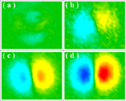
To observe the photonic SHE intuitively and verify the spin-dependent angular splitting, we also measure the Stokes parameter in our experiment. It is known that is a parameter to character the circular polarization Born1997 , where and represent the intensity of left- and right-circular polarization components, respectively. By separately recording the intensities after orthogonal circular polarizers, we calculate the Stokes parameter of the output beam from the metasurface for each point in the beam cross-section. Figure 5 is the processed results of , red and blue represent the opposite spin states. Figure 5(a) is the pattern for the incident position marked by the yellow circle in Fig. 2(b), which is an example for the situations with rotational symmetry [yellow circles in Fig. 2(b)-2(d)]. It is found that there is no splitting in these situations. Figures 5(b)-5(d) record the of emerging beams corresponding to the three metasurfaces with rotational symmetry breaking and different rotation rates. The incident positions are located at the same distance off the center of the metasurfaces which are marked by the green circles in Figs. 2(b)-2(d). It is found that the splitting is much more distinctness and stronger with the increasing of rotation rates, which proves that the spin-dependent splitting is proportional to the rotation rate of the metasurface agreeing well with our analysis.
As what we have discussed before, the angular splitting in real position space would allow us to direct observe the photonic SHE. However, observation of the spin-dependent splitting in experiment depends both on the constructed geometric phase gradient and the collimation of the beam. Our experiment results show that the rotation rates of the three applied metasurface are not big enough to show the intensity splitting. This is because that the splitting angle constructed in our experiment is less than the far field divergence angle Born1997 of incident Gaussian beam , which can be written as
| (7) |
where is the waist radius of Gaussian beam. The results in Fig. 5 demonstrate that the spin-dependent splitting can be enhanced by increasing the rotation rate of metasurface structure. Therefore, if we want to realize the spin-dependent splitting of intensity, we should ensure that the rotation rate is large enough to make the splitting angle much larger than the far field divergence angle of the incident beam .
IV Conclusions
In conclusion, we have demonstrated photonic SHE in metasurfaces with rotational symmetry breaking. In Ref. Yin2013 , this effect was explained in the context of the spin-orbit interaction of photons in a metasurface. Within their scheme, the metasurface structure can be regarded as a simple case of rotational symmetry breaking. From the viewpoint of geometric phases, the spin-dependent splitting is perpendicular to the designed phase gradient, and thereby is attributed to the RVB phase. In our scheme, the spin-dependent splitting is parallel to the designed phase gradient, and thereby is related to the PB phase. These interesting phenomena in optical near field has also been discussed in surface plasmon nanostructure with rotational symmetry breaking Bliokh2008I . In our scheme, the metasurfaces were constructed by dielectric nanograting and thereby the spin-dependent splitting can be detected in far field with high transmission efficiency. We also note that these results can be extrapolated to the electronic systems due to the similarly geometrical phase roots Karimi2012 . In addition, our results can be directly applied to the vector beams whose polarization takes a spatial rotation rate, namely exhibits an inhomogeneous polarization Zhan2009 ; Holleczek2011 ; Milione2011 ; Milione2012 ; Ling2014I . The PB phase can be regarded as an intrinsic property of vector beams, and spin-dependent splitting in momentum space would be visualized when the rotation symmetry is broken Ling2014II . We believe that these results may provide insights into the fundamental properties of photonic SHE and Pancharatnam-Berry phase.
Acknowledgements.
This research was partially supported by the National Natural Science Foundation of China (Grants Nos. 61025024, 11274106, and 11347120), and the Scientific Research Fund of Hunan Provincial Education Department of China (Grant No. 13B003).References
- (1) S. Murakami, N. Nagaosa, and S. C. Zhang, Science 301, 1348 (2003).
- (2) J. Sinova, D. Culcer, Q. Niu, N. A. Sinitsyn, T. Jungwirth, and A. H. MacDonald, Phys. Rev. Lett. 92, 126603 (2004).
- (3) J. Wunderlich, B. Kaestner, J. Sinova, and T. Jungwirth, Phys. Rev. Lett. 94, 047204 (2005).
- (4) O. Hosten and P. Kwiat, Science, 319, 787 (2008).
- (5) K. Y. Bliokh, Y. Gorodetski, V. Kleiner, and E. Hasman, Phys. Rev. Lett. 101, 030404 (2008).
- (6) M. Onoda, S. Murakami, and N. Nagaosa, Phys. Rev. Lett. 93, 083901 (2004).
- (7) K. Y. Bliokh and Y. P. Bliokh, Phys. Lett. A 333, 181 (2004).
- (8) K. Y. Bliokh and Y. P. Bliokh, Phys. Rev. Lett. 96, 073903 (2006).
- (9) C. Duval, Z. Horváth, and P. A. Horváthy, Phys. Rev. D 74, 021701(R) (2006).
- (10) K. Y. Bliokh, A. Niv, V. Kleiner, and E. Hasman, Nat. Photon. 2, 748 (2008).
- (11) X. Zhou, Z. Xiao, H. Luo, and S. Wen, Phys. Rev. A 85, 043809 (2012).
- (12) X. Zhou, X. Ling, H. Luo, and S. Wen, Appl. Phys. Lett. 101, 251602 (2012).
- (13) N. Shitrit, I. Yulevich, E. Maguid, D. Ozeri, D. Veksler, V. Kleiner, and E. Hasman, Science 340, 724 (2013).
- (14) Y. Qin, Y. Li, H. He, and Q. Gong, Opt. Lett. 34, 2551 (2009).
- (15) H. Luo, X. Zhou, W. Shu, S. Wen, and D. Fan, Phys. Rev. A 84, 043806 (2011).
- (16) Y. Gorodetski, K. Y. Bliokh, B. Stein, C. Genet, N. Shitrit, V. Kleiner, E. Hasman, and T. W. Ebbesen, Phys. Rev. Lett. 109, 013901 (2012).
- (17) X. Yin, Z. Ye, J. Rho, Y. Wang, and X. Zhang, Science 334, 1405 (2013).
- (18) Z. Bomzon, V. Kleiner, and E. Hasman, Opt. Lett. 26, 1424 (2001).
- (19) L. Marrucci, C. Manzo, and D. Paparo, Phys. Rev. Lett. 96, 163905 (2006).
- (20) Z. Zhao, J. Wang, S. Li, and A. E. Willner, Opt. Lett. 38, 932 (2013).
- (21) N. Shitrit, I. Bretner, Y. Gorodetski, V. Kleiner, and E. Hasman, Nano Lett. 11, 2038 (2011).
- (22) N. Yu, P. Genevet, M. A. Kats, F. Aieta, J.-P. Tetienne, F. Capasso, and Z. Gaburro, Science 334, 333 (2011).
- (23) A. V. Kildishev, A. Boltasseva, and V. M. Shalaev, Science 339, 1232009 (2013).
- (24) M. Beresna, M. Gecevicius, P. G. Kazansky, and T. Gertus, Appl. Phys. Lett. 98, 201101 (2011).
- (25) Y. Liu, X. Ling, X. Yi, X. Zhou, H. Luo, and S. Wen, Appl. Phys. Lett. 104, 191110 (2014).
- (26) M. Born and E. Wolf, Principles of Optics (University Press, Cambridge, 1997).
- (27) E. Karimi, L. Marrucci, V. Grillo, and E. Santamato, Phys. Rev. Lett. 108, 044801 (2012).
- (28) Q. Zhan, Adv. Opt. Photon. 1, 1 (2009).
- (29) A. Holleczek, A. Aiello, C. Gabriel, C. Marquardt, and G. Leuchs, Opt. Express 19, 9714 (2011).
- (30) G. Milione, H. I. Sztul, D. A. Nolan, and R. R. Alfano, Phys. Rev. Lett. 107, 053601 (2011).
- (31) G. Milione, S. Evans, D. A. Nolan, and R. R. Alfano, Phys. Rev. Lett. 108, 190401 (2012).
- (32) X. Ling, X. Zhou, W. Shu, H. Luo, and S. Wen, Sci. Rep. 4, 5557 (2014).
- (33) X. Ling, X. Yi, X. Zhou, Y. Liu, H. Luo, and S. Wen, arXiv:1407.7723 (unpublished).