Inter-mode reactive coupling induced by waveguide-resonator interaction
Abstract
We report on a joint theoretical and experimental study of an integrated photonic device consisting of a single mode waveguide vertically coupled to a disk-shaped microresonator. Starting from the general theory of open systems, we show how the presence of a neighboring waveguide induces reactive inter-mode coupling in the resonator, analogous to an off-diagonal Lamb shift from atomic physics. Observable consequences of this coupling manifest as peculiar Fano lineshapes in the waveguide transmission spectra. The theoretical predictions are validated by full vectorial 3D finite element numerical simulations and are confirmed by the experiments.
pacs:
42.25.Hz, 42.60.Da, 42.82.Gw,31.30.jfThe study of the consequences of coupling a physical system to an environment constitutes the central problem in the theory of open systems breuer . This coupling, on one hand, allows the system to dissipate energy through active decay channels. On the other hand, its reactive component leads to a shift of energy levels and oscillation frequencies of the system. Most celebrated examples of this physics involve an atom coupled to the bath of electromagnetic modes CCT4 , namely, the (dissipative) spontaneous emission of photons from an excited state SERydberg ; yablo ; Vos and the (reactive) Lamb shift of transition frequencies lamb ; lamb2 ; lamb3 .
Pioneering experimental studies in late 1970’s cpt-pisa showed that destructive interference of different decay paths, leading to the same final continuum, can suppress absorption by a multilevel atom via the so-called Coherent Population Trapping (CPT) arimondo_review and Electromagnetically Induced Transparency (EIT) EITexp1 ; EITreview mechanisms. While originally these phenomena were discovered in the atomic physics context, a continuous interest has been devoted to analogous effects in solid-state systems EITsolidstate , photonic devices matsko ; lipson ; 21 ; 20 ; 22 ; EIT_THZ ; oeHuang , and, very recently, optomechanical systems OMIT . Though in most experiments only the dissipative features are affected by the interference, the theory predicts that a similar phenomenon should also occur on the reactive coupling side breuer .
In photonics, the presence of a waveguide in the vicinity of a resonator activates new radiative decay channels for the resonator modes via emission of light into the waveguide mode photonicsbook ; photonicsbook2 ; yariv . The corresponding reactive effect is a shift of the resonator mode frequencies, which can be interpreted as the photonic analogue of the atomic Lamb shift. In this Letter, we report on a joint theoretical and experimental study of a photonic device in which pairs of modes of very similar frequencies are coupled simultaneously to the same waveguide mode. Both the dissipative and the reactive couplings of the cavity modes to the waveguide turn out to be modulated by interference phenomena between the two modes, which can be summarized as environment-induced inter-mode coupling – a sort of off-diagonal Lamb shift in the atomic analogy. In the experiments, these coupling terms are responsible for peculiar Fano interference lineshapes in the transmission spectra of single resonators.
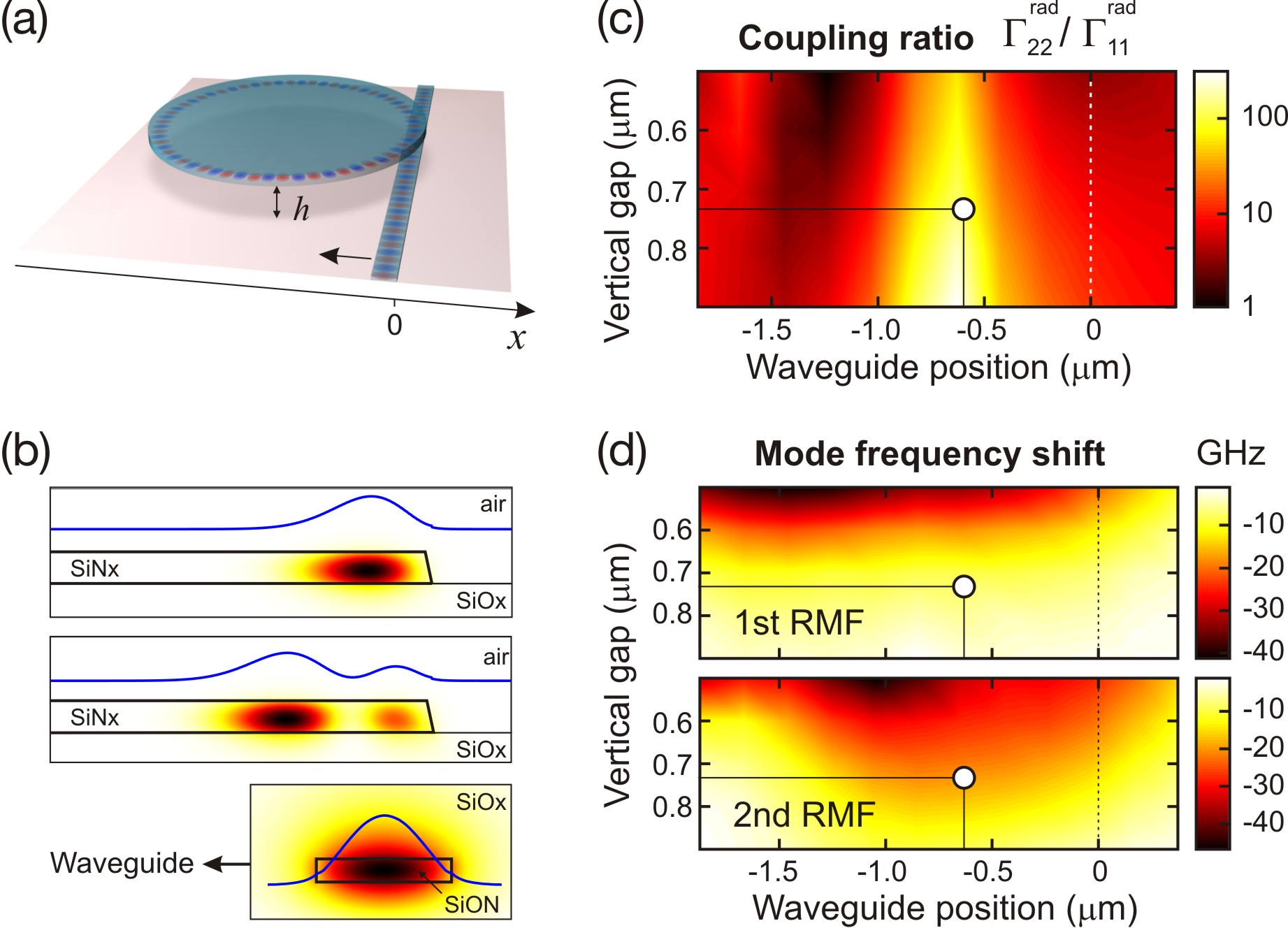
The system under consideration consists of a thin microdisk resonator vertically coupled to an integrated single-mode waveguide located below the disk (Fig. 1(a)). In contrast to the traditional lateral coupling geometry, where typically only the most external first radial mode family (RMF) experiences an appreciable coupling to the waveguide, the vertical coupling geometry allows for an independent lateral and vertical positioning of the waveguide, permitting thus to freely tune the coupling to the different mode families, in particular to the more internal ones mherIEEE ; verticup . Since these latter typically have lower intrinsic quality factors, the vertical coupling geometry is crucial to our experiments, as it allows for several RMFs to be simultaneously close to critical coupling and, therefore, visible in transmission spectra.
This remarkable tunability is illustrated in Fig.1(c,d). An ab initio finite element numerical simulation of the 3D vectorial Maxwell equations, including the detailed geometrical shape and material composition of the resonator-waveguide system, is used to obtain the frequencies and damping rates of the different eigenmodes of the electromagnetic wave equation SM . At this stage, we have focussed on a pair of spectrally distinct modes, in order to minimize the contribution from mode-coupling terms. The ratio of the decay rates (Fig.1(c)) is proportional to the relative intensity of the waveguide coupling to the lowest two RMFs of the resonator: as expected, its value is the largest when the lateral position of the waveguide matches the main lobe of the the second RMF (Fig.1(b) middle panel). The photonic analogue of the atomic Lamb shift for (independent) cavity modes is illustrated in Fig.1(d): the shifts and of the two modes from their bare frequencies are plotted as a function of the waveguide position. While in the atomic case the calculation of the Lamb shift, originating from photon emission/reabsorption processes, requires sophisticated techniques and a careful handling of UV divergences CCT4 , in the photonic case one typically has a red-shift of all modes when a generic dielectric material is approached to a resonator photonicsbook .
Theoretical model –
The transmission of a waveguide, , coupled to the resonator can be described by generalizing the input-output theory of optical cavities Walls to the multi-mode case. In the present two-mode case, the equation of motion for the field amplitudes can be written as
| (1) |
In the absence of the waveguide, the two modes oscillate independently from each other at a bare frequency and have an intrinsic, non-radiative decay rate . The incident field, which propagates along the waveguide and drives the resonator, is described in the last term in Eq. (1). The coupling amplitude of the driven waveguide mode to the resonator mode is quantified by the coefficients. In the following, we focus on a monochromatic excitation with .
The effect of the waveguide on the cavity mode oscillation is included in the motion equation Eq. (1) via the Hermitian and matrices, for which formal application of the theory of open systems within the Markov approximation breuer provides the general expression
| (2) |
in terms of the coupling amplitude of the th resonator mode to that of the waveguide of longitudinal wavevector , mode index , and frequency . For single-mode waveguides, is determined by the single propagating mode for which and . This imposes that the coefficient, typically responsible for EIT-like interference effects in the atomic context, is related to the radiative linewidths by .
Even though a quantitative estimation of using Eq. (2) is in most cases impractical as it involves a sum over all (both guided and non-guided) waveguide modes, this equation provides an intuitive picture of the underlying process: the diagonal and off-diagonal terms originate from the virtual emission of a photon from a resonator mode and its immediate recapture by the same or another mode, respectively. From a qualitative point of view, while the diagonal terms are typically , we are unable to invoke any general argument to determine the non-diagonal . A similar inter-mode coupling term was mentioned in 20 starting from a coupled-mode approach. Here we will show how a real is needed to reproduce the experimental data and we will point out some unexpected features due to this term.
In our model, the waveguide transmission reads , in terms of the stationary solution of the motion equations Eq. (1) and the density of states in the waveguide. When the waveguide is effectively coupled to one resonator mode only, a typical resonant transmission dip is recovered: under-, critical-, and over-coupling regimes are found depending on whether is lower, equal or larger than photonicsbook ; photonicsbook2 ; yariv .
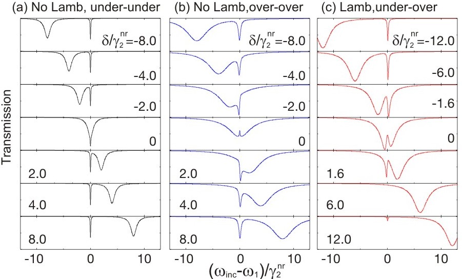
The novel and much richer phenomenology that occurs in the two-mode case is illustrated in Fig. 2. Interesting features manifest clearly when both resonator modes are close to criticality . In the left column of Fig. 2, we show a case where both modes are slightly under-coupled and the off-diagonal reactive coupling vanishes . Each mode then manifests as a transmission dip in the spectrum centered at a frequency that includes the diagonal shift . Note that the the first RMF is much narrower than the other since . Comparing the different rows of the figure, we notice that scanning the relative detuning of the two modes results in a simple, interference-free superposition of the two dips. Even in this simplest case, a correct inclusion of is, however, essential to avoid the appearance of nonphysical features in the calculations, such as .
The central column shows the case of slightly over-coupled modes , still with . Now, marked interference features start to appear due to the off-diagonal dissipative coupling and the doublets of peaks acquire a complicated structure. In particular, the narrow dip, normally visible at (1st and 7th rows), is replaced by a complex Fano-like lineshape fano1 ; CCT4 (3rd and 5th) for moderate detunings, and even reverses its sign into a transmitting EIT feature in the resonant case (4th row). Experimental observations of this physics were recently reported in 21 ; 22 ; 20 .
Finally, the dramatic effect of the off-diagonal reactive coupling is shown in Fig. 2(c). As most visible general feature, the spectrum is no longer symmetric under a change in the sign of , and the spectral feature due to the narrow mode is clearly visible than one would expect given its deep under-coupling condition. With respect to the case shown in Fig. 2(b), the narrow Fano feature has a reversed sign for moderate detunings (3rd and 5th rows). Furthermore, it is suppressed in a finite detuning range (6th row). An analytical explanation of this unexpected effect is given in SM in terms of the destructive interference of the direct excitation of mode 1 from the waveguide and its two-step excitation via mode 2 by the off-diagonal terms of and . The two paths almost cancel out around .
Numerical simulations –
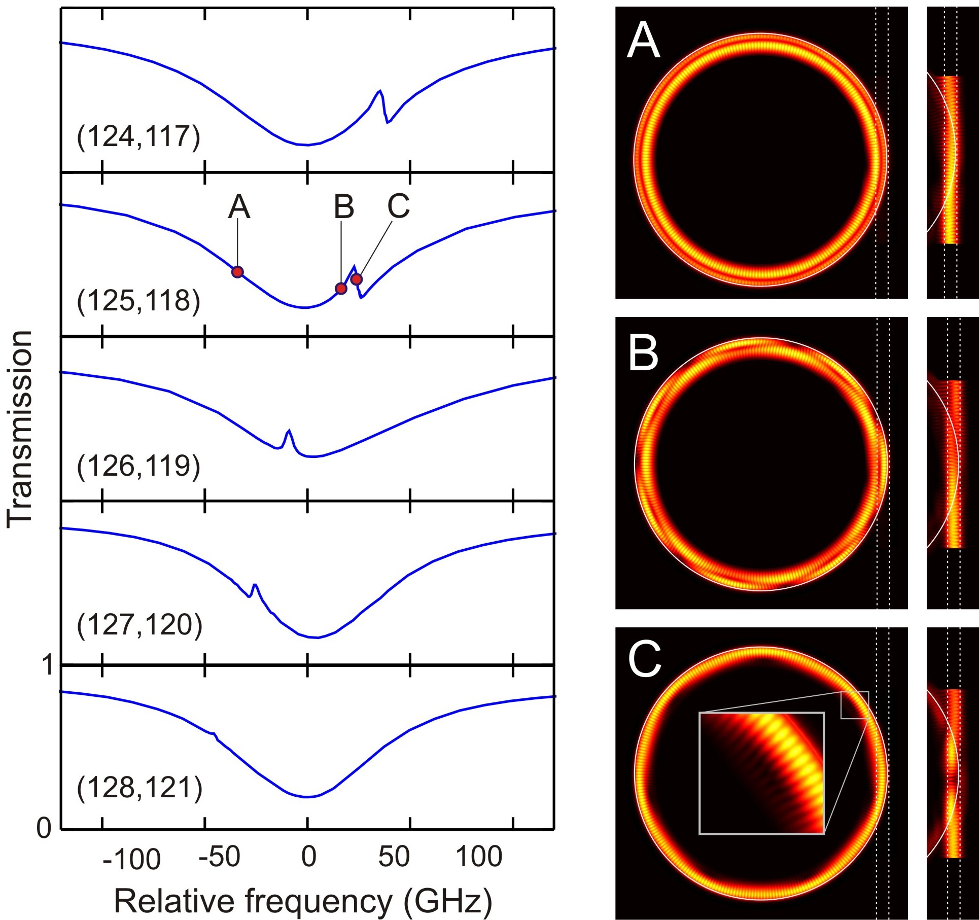
The analytical predictions for the transmission have been validated through ab initio finite element numerical simulations SM . The slightly diverse free spectral range of the different RMFs allowed us to scan the relative detuning of the interfering modes by looking at pairs of quasi-resonant modes with different azimuthal quantum numbers. Examples of spectra are shown in the left panels of Fig. 3. The qualitative agreement with the predictions of Eq. (2) in the regime is remarkable: the Fano-like feature is clearly visible with the correct sign for generic detunings (1st to 4th rows) and disappears completely in a well-defined range of ’s (lowest row). The three (A,B,C) panels on the right column of Fig. 3 show horizontal cuts of the field intensities in the resonator and the waveguide at three different incident frequencies across the Fano-like feature. While the excitation at the A (C) point is concentrated in the second (first) mode, interference between the two modes is responsible for the snaky shape of the intra-cavity intensity distribution at the intermediate point B. As expected, the number of spatial oscillations is determined by the difference in azimuthal quantum numbers of the two resonator modes.
Experimental observations –
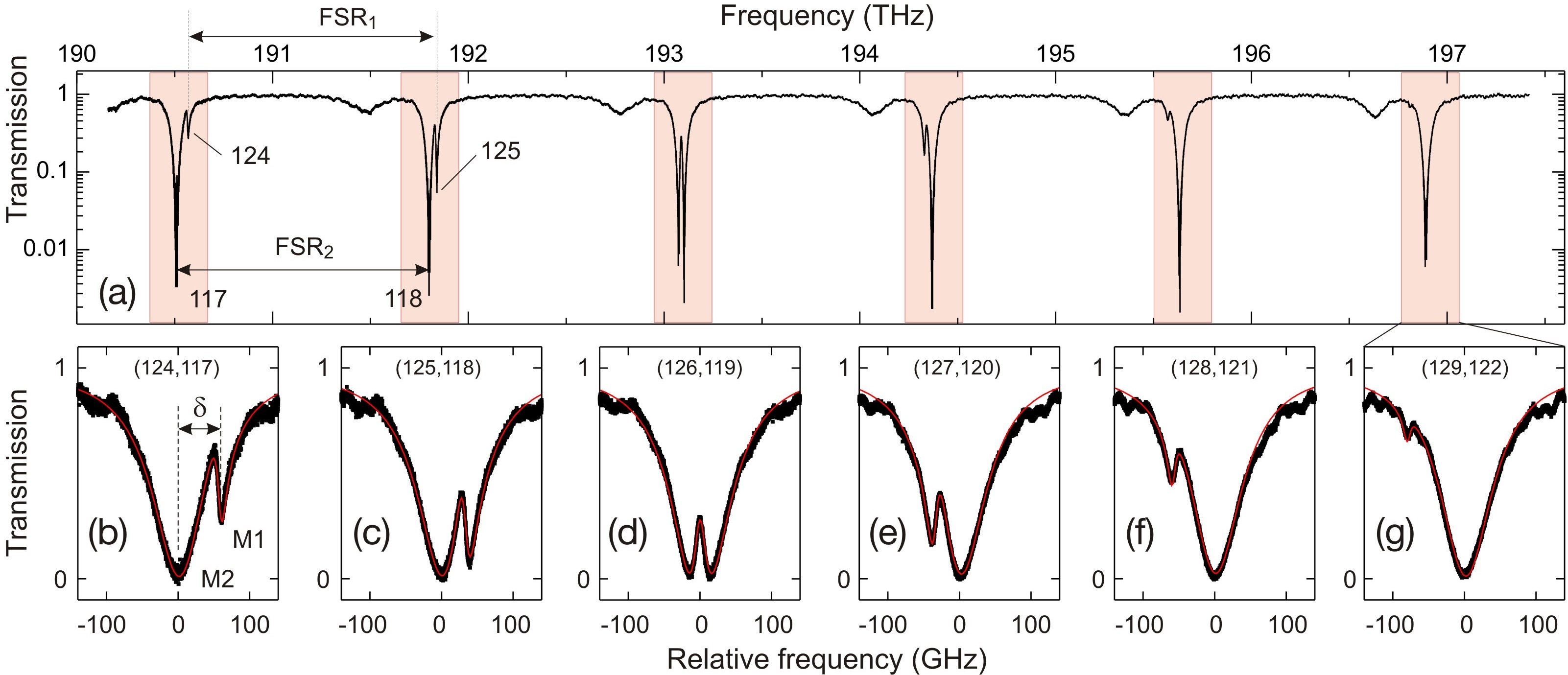
We have validated our findings experimentally by looking at pairs of quasi-resonant modes originating from different radial families in microdisk resonators coupled vertically to dielectric waveguides. The experimental transmission spectrum through the waveguide for a microdisk of radius m is shown in the upper panel of Fig. 4 SM . The spatial position of the waveguide is indicated by open dots in Fig.1(c-d). The transmission spectrum consists of a sequence of doublets originating from the first (narrow features) and second (broader features) RMFs, which have slightly diverse free spectral range. This last permits to sweep one RMF across the other as the azimuthal order of the underlying modes is increased, and the doublets structure is correspondingly changed. In the bottom panels Fig. 4(b-g), zoomed views of the different doublets are shown: to facilitate comparison, in each of these panels the central frequency is located at the broader second family resonance (i.e. at in the analytical model). These spectra are in excellent qualitative agreement with the predictions of the numerical simulations shown in Fig. 3: the Fano-like feature has the correct sign and is visible for generic detunings exception made for a small range of values where it completely disappears [panel (g)]. Moreover, the experimental data are successfully fitted by the analytical model (red curves in Fig. 4(b-g)).
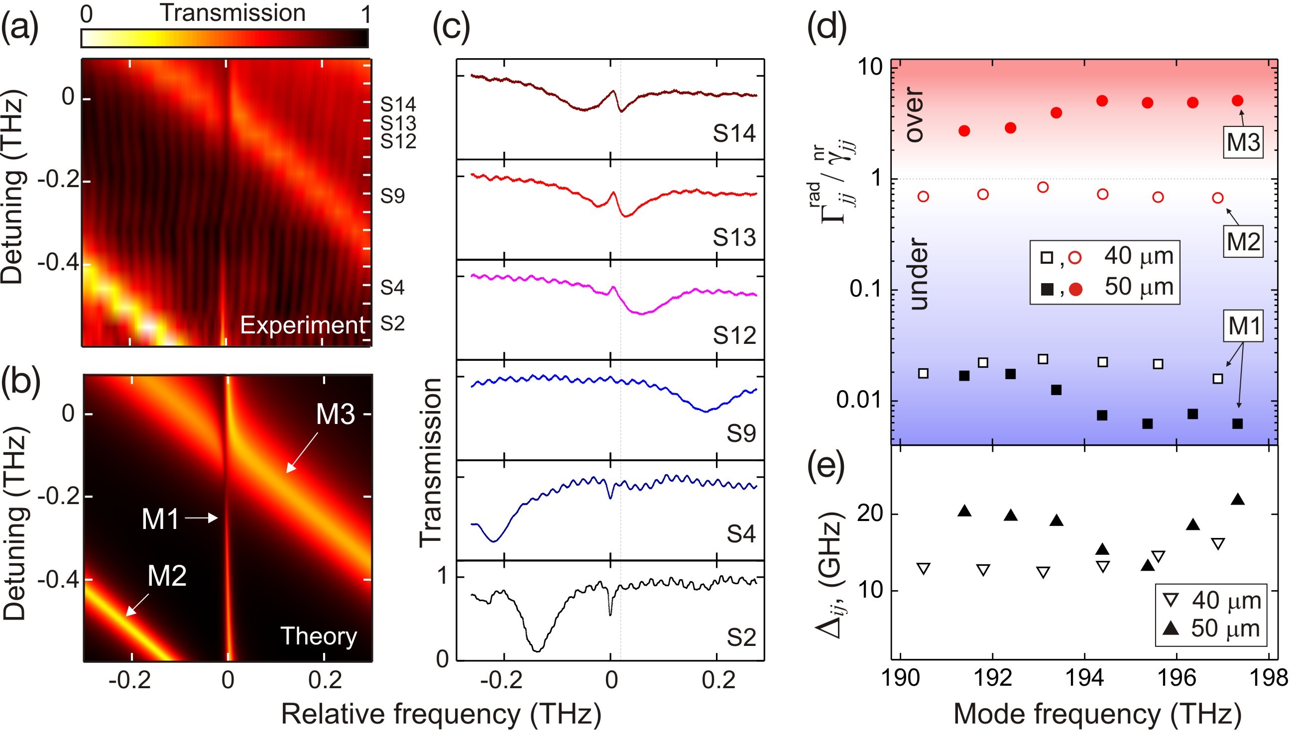
The generality of our observations has been confirmed by repeating the experiment on a larger m resonator in which the Fano interference takes place between the first and the third RMFs. The measured transmission spectra are shown in Fig. 5(a,c) for different values of the relative detuning of the quasi-resonant pairs of modes. The crossing of the two families again leads to Fano interference profiles, and the narrow feature disappears in a specific range of detunings (spectrum S9). Furthermore, the experimental results successfully compared to the prediction of the analytical model, generalized to three modes (Fig. 5(b)).
Finally, Fig. 5(d-e) summarizes the fits parameters for both m and m resonators. Despite the total independence of the fit procedures performed on each spectrum, a smooth dependence of all fit parameters on the azimuthal mode number is observed. As expected, the scan of the azimuthal quantum number varies the mode detuning without affecting the other system parameters. From the top graph we notice that in both cases the first family modes are undercoupled to the waveguide, while the second and third family modes are very close to critical coupling. As stated in the theoretical section, this combination of couplings is crucial for a neat observation of the Fano feature. Finally, Fig. 5(e) shows that the fitted value of the off-diagonal reactive coupling is always around GHz.
To summarize, in this work we have reported a joint theoretical and experimental study of a microdisk resonator vertically coupled to a single-mode waveguide. The importance of the inter-mode reactive coupling due to the neighboring waveguide is revealed and characterized from the peculiar Fano lineshapes manifesting in transmission spectra. In addition to its intrinsic interest for photonics, our study provides a simple model where to study a fundamental feature of the theory of open systems, namely the possibility of environment-mediated couplings – the off-diagonal photonic Lamb shift – between different modes of a system.
We acknowledge financial support Autonomous Province of Trento, Call ”Grandi Progetti 2012”, project ”On silicon chip quantum optics for quantum computing and secure communications - SiQuro”. IC acknowledges partial support from ERC via the QGBE grant.
References
- (1) H.-P. Breuer and F. Petruccione, The Theory of Open Quantum Systems (Oxford University Press, Oxford, 2002).
- (2) R.G. Hulet, E. S. Hilfer, and D. Kleppner, Phys. Rev. Lett. 55, 2137 (1985).
- (3) E. Yablonovitch, Phys. Rev. Lett. 58, 2059 (1987).
- (4) P. Lodahl, A. F. van Driel, I. S. Nikolaev, A. Irman, K. Overgaag, D. Vanmaekelbergh, and W. L. Vos, Nature 430, 654 (2004).
- (5) W. E. Lamb and R. C. Retherford, Phys. Rev. 72, 241 (1947).
- (6) T. W. Hänsch , I. S. Shahin, and A. L. Schawlow, Nature 235, 63 (1972).
- (7) A. Lempicki, L. Andrews, S. J. Nettel, B. C. McCollum, and E. I. Solomon, Phys. Rev. Lett. 44, 1234 (1980).
- (8) C.Cohen-Tannoudji, J.Dupont-Roc and G.Grynberg, Processus d’interaction entre photons et atomes, (InterEditions, Editions du CNRS, Paris, 1988).
- (9) G. Alzetta, A. Gozzini, L. Moi, and G. Orriols, Nuovo Ciment. B 36, 5 (1976).
- (10) E. Arimondo, Prog. Optics 35, 257 (1996).
- (11) K.-J. Boller, A. Imamoglu, and S. E. Harris, Phys. Rev. Lett. 66, 2593 (1991).
- (12) M. Fleischhauer, A. Imamoglu, and J. P. Marangos, Rev. Mod. Phys. 77, 633 (2005).
- (13) D. Brunner, B. D. Gerardot, P. A. Dalgarno, G. Wüst, K. Karrai, N. G. Stoltz, P. M. Petroff, and R. J. Warburton, Science 325, 70 (2009).
- (14) Q. Xu, S. Sandhu, M. L. Povinelli, J. Shakya, S. Fan, and M. Lipson, Phys. Rev. Lett. 96, 123901 (2006).
- (15) Y.-F. Xiao, L. He, J. Zhu, and L. Yang, Appl. Phys. Lett. 94, 231115 (2009).
- (16) B.-B. Li, Y.-F. Xiao, C.-L. Zou, Y.-C. Liu, X.-F. Jiang, Y.-L. Chen, Y. Li, and Q. Gong, Appl. Phys. Lett. 98, 021116 (2011).
- (17) C.-H. Dong, C.-L. Zou, Y.-F. Xiao, J.-M. Cui, Z.-F. Han, and G.-C. Guo, J. Phys. B: At. Mol. Opt. Phys. 42, 215401 (2009).
- (18) J. Gu, R. Singh, X. Liu, X. Zhang, Y. Ma, S. Zhang, S. A. Maier, Z. Tian, A. K. Azad, H.-T. Chen, A. J. Taylor, J. Han, and W. Zhang, Nat. Commun. 3, 1151 (2012).
- (19) Q. Huang, Z. Shu, G. Song, J. Chen, J. Xia, and J. Yu, Opt. Express 22, 3219 (2014).
- (20) L. Maleki, A. B. Matsko, A. A. Savchenkov, and V. S. Ilchenko, Opt. Lett. 29, 626 (2004).
- (21) S. Weis, R. Rivière, S. Deléglise, E. Gavartin, O. Arcizet, A. Schliesser, T. J. Kippenberg, Science 330, 1520 (2010).
- (22) A. B. Matsko, Practical Applications of Microresonators in Optics and Photonics (CRC Press, New York, 2009).
- (23) D. L. Lee, Electromagnetic Principles of Integrated Optics (Wiley, New York, 1986).
- (24) A. Yariv, Electron. Lett. 36, 321 (2000).
- (25) M. Ghulinyan, R. Guider, G. Pucker, and L. Pavesi, IEEE Photonics Technol. Lett. 23, 1166 (2011).
- (26) M. Ghulinyan, F. Ramiro-Manzano, N. Prtljaga, R. Guider, I. Carusotto, A. Pitanti, G. Pucker, and L. Pavesi, Phys. Rev. Lett. 110, 163901 (2013).
- (27) See Supplemental Material
- (28) D. F. Walls, G. J. Milburn, Quantum Optics (Springer, Berlin, 1994).
- (29) U. Fano, Phys. Rev. 124, 1866 (1966).