Pentamode metamaterials with independently tailored bulk modulus and mass density
Abstract
We propose a class of linear elastic three-dimensional metamaterials for which the effective parameters bulk modulus and mass density can be adjusted independently over a large range—which is not possible for ordinary materials. First, we systematically evaluate the static mechanical properties and the phonon dispersion relations. We show that the two are quantitatively consistent in the long-wavelength limit. To demonstrate the feasibility, corresponding fabricated polymer microstructures are presented. Finally, we discuss calculations for laminates composed of alternating layers of two different metamaterials with equal bulk modulus yet different mass density. This leads to metamaterials with effectively anisotropic uniaxial dynamic mass density tensors.
The mechanical properties mass density and bulk modulus (the inverse of the compressibility) are strongly correlated for ordinary substances. For example, an ideal gas held at temperature follows the universal relation Nag (2005); García-Chocano et al. (2012). There is no such strict relation for solids, but one gets a rough general correlation between the Young’s modulus and () in the so-called Ashby plot Ashby (2010); Zheng et al. (2014). For constant Poisson’s ratio, this correlation translates to . Recently, ultralight-weight three-dimensional mechanical microlattices have been investigated by different groups Kistler (1987); Tillotson and Hrubesh (1992); Schaedler et al. (2011); Mecklenburg et al. (2012); Jang et al. (2013); Bauer et al. (2014); Zheng et al. (2014). Herein, ideally, one aims at reasonably small compressibility, i.e., at reasonably large for small . To another extreme, one may also want materials with large yet small .
For example, in the context of coordinate-transformation mechanics Milton et al. (2006); Norris (2008); Brun et al. (2009); Olsson and Wall (2011); Norris and Parnell (2012); Norris et al. (2013); Craster and Guenneau (2013); Diatta and Guenneau (2014), the ability to independently adjust and of a mechanical material at each point in space is crucial. For general cloaking structures, one would even like to tailor inhomogeneous anisotropies Scandrett et al. (2010); Cipolla et al. (2011). This is in analogy to transformation optics Pendry et al. (2006); Leonhardt (2006) based on the Maxwell equations, where the inverse electric permittivity (tensor) is the counterpart of the bulk modulus (tensor) and the magnetic permeability (tensor) is the counterpart of the mass density (tensor) in mechanics Norris (2008); Cummer et al. (2008). Here, we have tacitly assumed that the shear modulus is zero or at least small. Otherwise, there is no such simple correspondence between mechanics and electromagnetism Milton et al. (2006).
How can we obtain the aimed-at independent control of and with an artificial crystal? We start from three-dimensional pentamode metamaterials Milton and Cherkaev (1995); Sigmund (1995); Kadic et al. (2012, 2013a); Schittny et al. (2013); Mejica and Lantada (2013); Spadoni et al. (2014), the counterpart of bimode metamaterials in two dimensions Layman et al. (2013). These artificial materials have an effective shear modulus that is orders of magnitude smaller than their effective bulk modulus, i.e., their effective Poisson’s ratio approaches 0.5 from below. This can be achieved Kadic et al. (2012); Schittny et al. (2013) by a lattice of needle-like objects, the conical tips of which touch each other on a diamond lattice with corresponding face-centered cubic (fcc) lattice constant Kadic et al. (2012). The key aspect for the present paper is the following: Upon exerting a hydrostatic pressure onto the pentamode structure, the stress field is essentially concentrated to the tip touching regions and their immediate surroundings, see Fig. 1 (the underlying numerical calculations will be specified below). The stress is negligible in the other parts. This means that the other parts do not significantly influence the elastic properties at all. We can thus add mass to these other regions to independently tailor the mass density without affecting . The volume filling fraction of fabricated microscopic Kadic et al. (2012) and macroscopic Schittny et al. (2013) ordinary pentamode metamaterials has been as small as a few per cent and yet much smaller values of are conceptually possible. This leaves plenty of room towards the ultimate maximum of . Thus, the mass density can be varied over an order of magnitude with present fabrication technology and conceptually even much more—while fixing the bulk modulus . To be able to efficiently fill the volume and keep the overall structure simple at the same time, we have chosen the regions outside of the conical touching tips to be conical in shape as well. Their large diameter is . Importantly, when changing , the shape of the tips does not change at all, leading to a decoupling of the tips from the rest (see Fig. 1). The tips are illustrated in red, whereas the rest is highlighted in blue—although both are made from the identical constituent material.
We have shown previously Kadic et al. (2012) that the isotropic bulk modulus of ordinary pentamode metamaterials is simply proportional to the small diameter of the touching region (see Fig. 1), provided that and . Varying the ratio , and hence , while maintaining the condition for fixed , seems possible over an order of magnitude with present technology. Again, conceptually, yet larger ranges are possible. In the same limit the shear modulus is negligible, i.e., Kadic et al. (2012).
To summarize, for sufficiently small values of the small connection diameter, i.e., for , the ratio determines the ratio of the effective isotropic bulk modulus and the isotropic constituent material bulk modulus, . The big diameter with respect to the lattice constant, , mainly determines the volume filling fraction and hence the effective static mass density via , with the mass density of the constituent material .
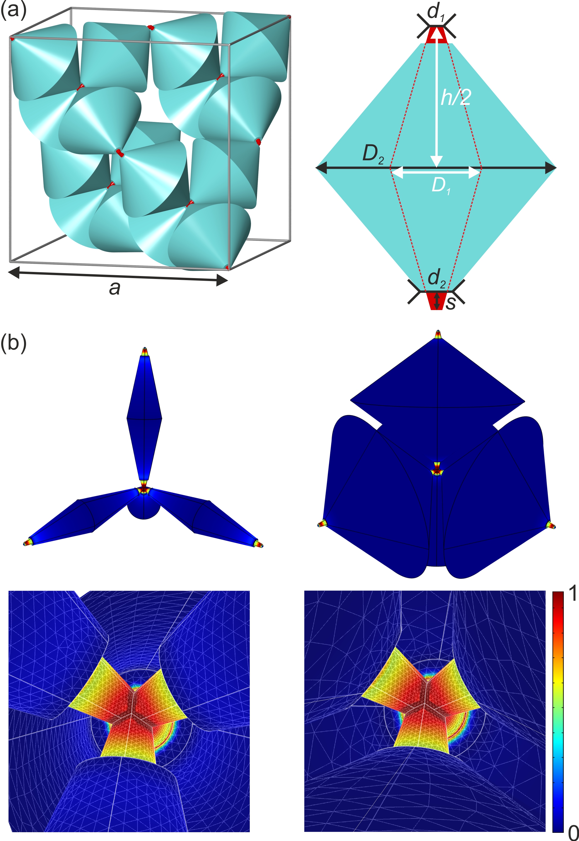
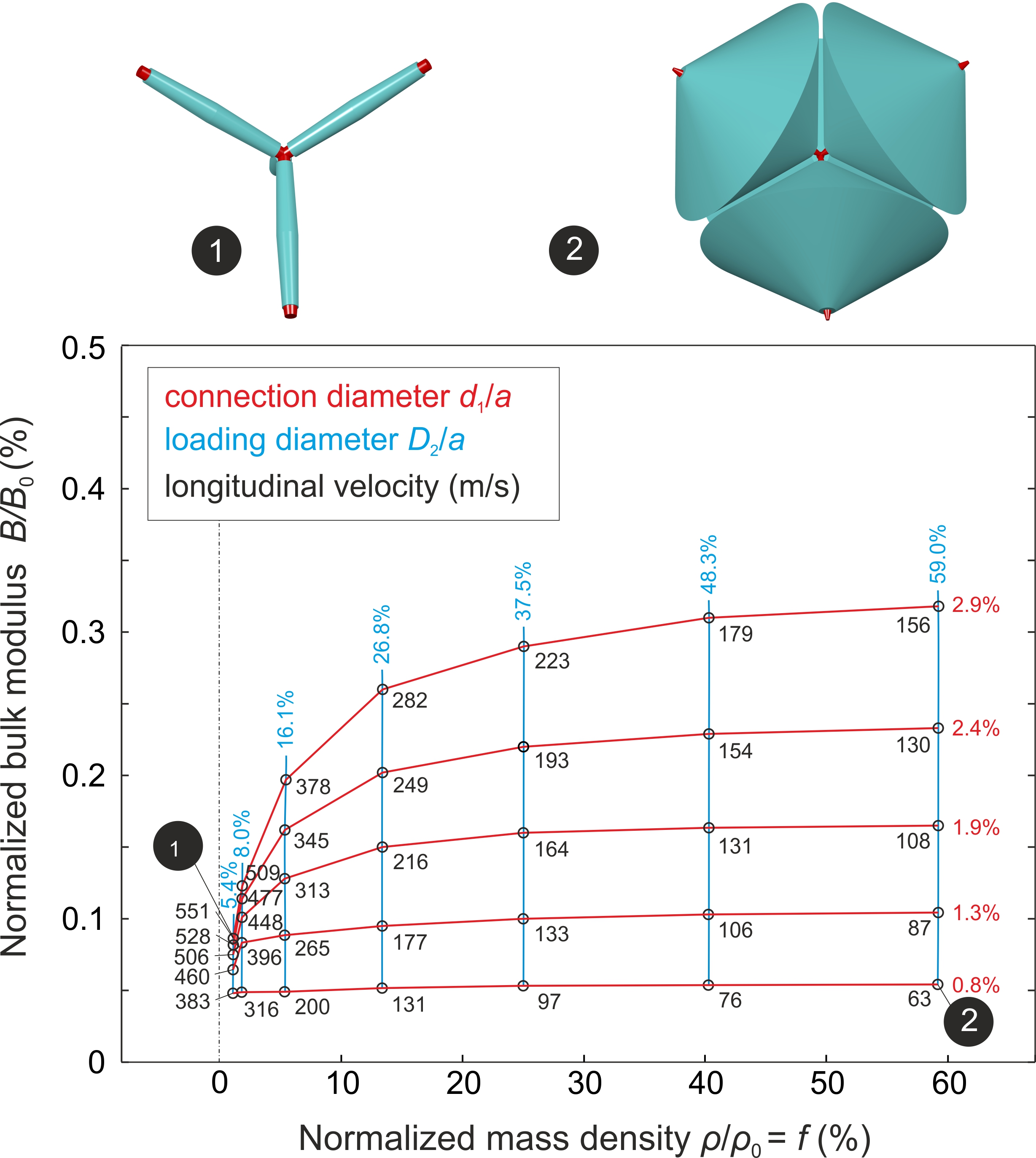
Figure 2(a) illustrates the properties of the considered metamaterials in the plane. Two selected extreme unit cells are shown for illustration. The red curves correspond to different values of constant ratio , the blue curves to different fixed ratios . We emphasize once again that the decoupling becomes strict in the limit (in which case the blue and red curves should all be horizontal and vertical straight lines, respectively), but one can see from Fig. 2 that the decoupling already works approximately for ratios in the range of just a few per cent. The calculations for the effective bulk modulus have been performed by numerically solving the continuum-mechanics equations using the commercial software package COMSOL Multiphysics (MUMPS solver, degrees of freedom) and by applying a hydrostatic pressure from all sides of a structure composed of one extended fcc unit cell as in Bückmann et al. (2014a). For the constituent material, we take typical polymer parameters, i.e., a bulk modulus of , a mass density of , and a Poisson’s ratio of . As discussed previously Kadic et al. (2012), the latter is not important at all and the others can easily be scaled (see below). The calculations for the effective mass density are simply based on the polymer volume filling fraction.
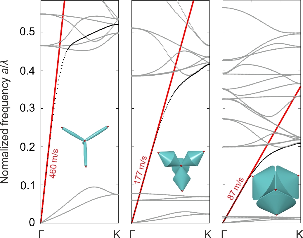
Within the framework of continuum mechanics considering pentamode metamaterials (i.e., negligible shear resistance), the phase velocity of longitudinally polarized compression waves is given by (= sound velocity). The acoustic wave impedance is .
To connect static continuum mechanics to elastic wave propagation, we have also calculated the phonon band structures of the modified pentamode metamaterials systematically as a function of the two design parameters and . We consider the polymer structure in vacuum and again use COMSOL Multiphysics (MUMPS solver, Floquet-Bloch periodic boundary conditions imposed onto the primitive unit cell, about degrees of freedom, compare Martin et al. (2012)). Examples are exhibited in Fig 3. We only depict wave vectors along the K direction because we have previously shown that the pentamode dispersion relation is isotropic at small Martin et al. (2012) although the structure itself has only cubic symmetry. Obviously, static continuum mechanics (red straight line) and dynamic wave propagation (black points) are quantitatively consistent in regard to the effective longitudinal phase velocities within the long-wavelength or effective-medium limit. More derived phase velocities are presented as the numbers at the data points in Fig. 2. For all combinations of and , the longitudinal phase velocity derived from the band structure, , and that derived from continuum mechanics, , agree to within less than relative difference. This agreement for all parameters strongly suggests that, for the metamaterial, the effective dynamic mass density is closely similar to the static mass density and, likewise, the effective dynamic bulk modulus is closely similar to the static bulk modulus. In general, the dynamic mass density can be quite different from the static mass density Mei et al. (2007).
The slower transversely polarized shear modes connected to soft shear springs as well as the flat “deaf” bands, which correspond to localized vibrations of the masses, are de-emphasized in light gray. As to be expected, these flat bands move downwards in frequency in the calculations with increasing mass (i.e., larger ) and/or with decreasing spring constant (i.e., smaller ). In an intentionally inhomogeneous structure, one might couple to these modes though. This could be avoided by choosing operation frequencies outside of these flat bands.
In passing, we emphasise again the scalability of our results: The dimensionless normalized frequencies on the horizontal axes of Fig. 3 refer to a wavelength in standard air (at 20 degrees Celsius) with an air velocity of sound . The absolute frequency in units of Hz results from the dispersion relation . Comparing to air is meaningful because one may eventually couple such structures to airborne sound. In any case, it is simple to scale the wavelength to other media. For example, for a lattice constant of and for the above polymer constituent material parameters, a normalized frequency of corresponds to an absolute frequency of . On the basis of the continuum-mechanics equations, it is also straightforward to scale our results to metamaterials made from other constituent materials. For a constituent material bulk modulus and mass density , instead of our above choices and , one gets .
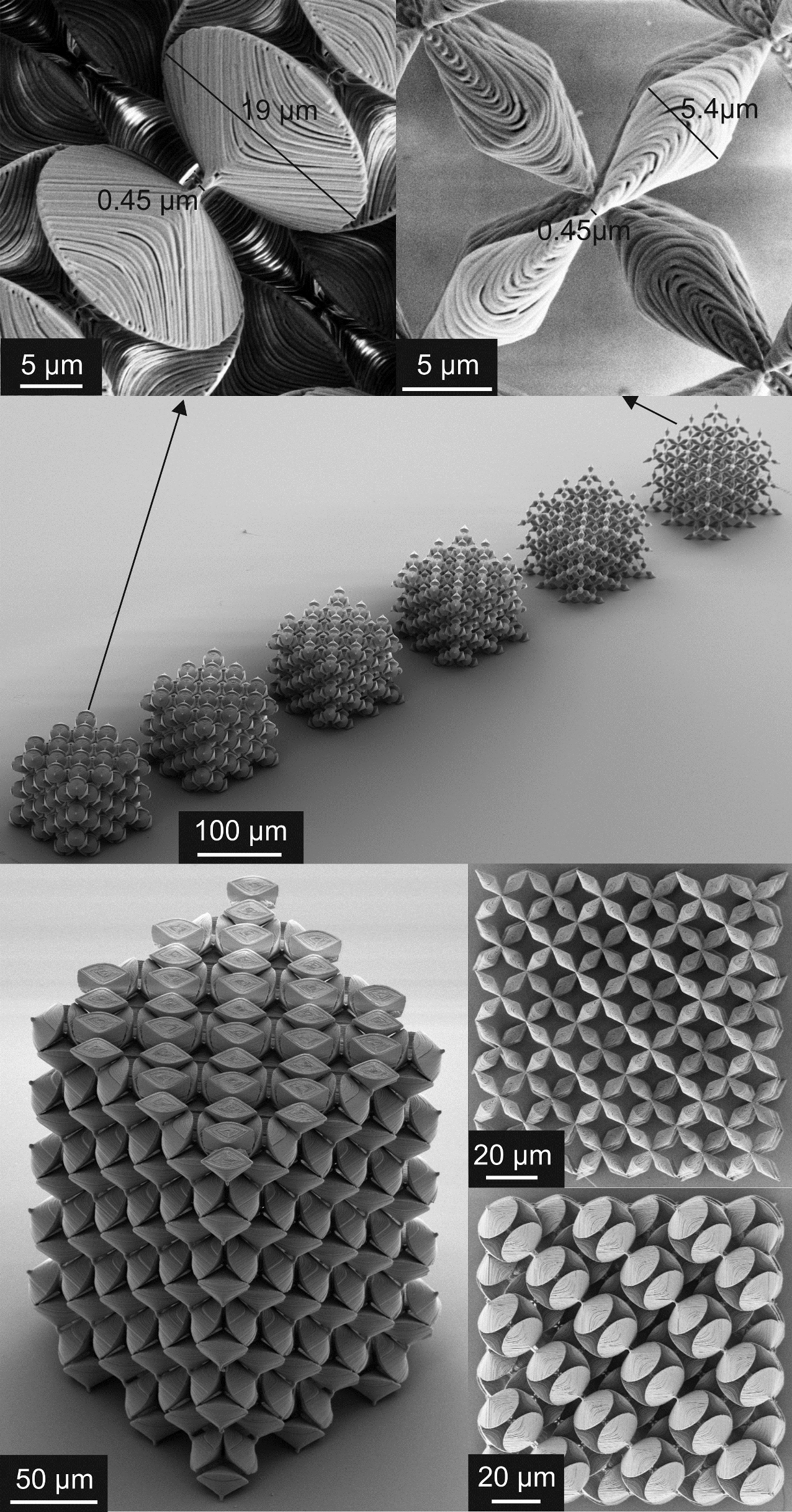
Are such complex modified pentamode metamaterials with fine features at the connections and large masses in between experimentally feasible with current technology? Would the connections collapse under the large weight? To address these questions, we have fabricated polymer-based test samples with a lattice constant of using state-of-the-art three-dimensional dip-in galvo-scanner-based optical laser lithography (Nanoscribe GmbH, Photonic Professional GT). Details of this technology can be found in Bückmann et al. (2014b, a). Electron micrographs of fabricated metamaterial samples are depicted in Fig. 4. Obviously, the structures are of high quality and the necessary aspect ratios and extreme three-dimensional motifs are possible. However, within current state-of-the-art, we can only fabricate up to around extended fcc unit cells Bückmann et al. (2014a) on a timescale of ten hours. For meaningful wave measurements that are not dominated by edge effects, one rather needs around extended fcc unit cells or more. These would require excessive writing times on the scale of half a year. Such structures may come into reach though in some years as three-dimensional micro-printing gets yet faster.
Next, as a conceptual application example, we consider laminates made of two different modified pentamode metamaterials to obtain effectively anisotropic dynamic mass density tensors. It is well known that laminates composed of alternating layers of locally isotropic materials can lead to effectively anisotropic metamaterial behavior Kadic et al. (2013b). A simple case is a stack of alternating good and bad electrically conducting layers that leads to large conductivity for currents flowing in the plane and small conductivity normal to the plane Milton (2002); Kadic et al. (2013b). We aim at a similar anisotropic behavior for the phase velocity of longitudinal waves propagating in the plane of the layers and normal to them, respectively. Using the metamaterials introduced above, we can now consider a special situation in which all the layers have the same bulk modulus, but where the mass density is alternating between high and low with a contrast of, e.g., about a factor of ten. Correspondingly, we expect the wave propagation anisotropy to be due to the mass density tensor anisotropy only.
Figure 5 summarizes band structure calculations for laminates composed of bulk layers for reference (panel (a)) and for the actual complex laminate metamaterial structure (panel (b)), respectively. Here, each laminate layer has a thickness of one extended fcc pentamode lattice constant . This leads to the complex heterostructure illustrated in Fig. 4(b). Slow acoustic bands emerging from the zone center corresponding to transverse waves connected to the small shear modulus as well as bands corresponding to modes with flat dispersion (roughly related to optical phonons in ordinary crystals with a two-atom basis) are again plotted in light gray to emphasize in color the more important longitudinal acoustic compression waves connected to the bulk modulus. In the true long-wavelength limit, we find an isotropic behavior for the phase velocity . This is expected for any type of structure because all masses oscillate in phase in the quasi-static limit Milton (2002); Kadic et al. (2013b). For higher frequencies, yet for wave vectors still well separated from the edge of the first Brillouin zone (this means the effective-medium description is appropriate), the bands for wave propagation in the plane of the laminate layers and normal to them, respectively, separate (compare red and green curves in the middle). The normal (-direction) mode crosses the various rather flat optical-phonon-like bands as a straight line, whereas the mode propagating in the plane of the layers (-plane) bends over.
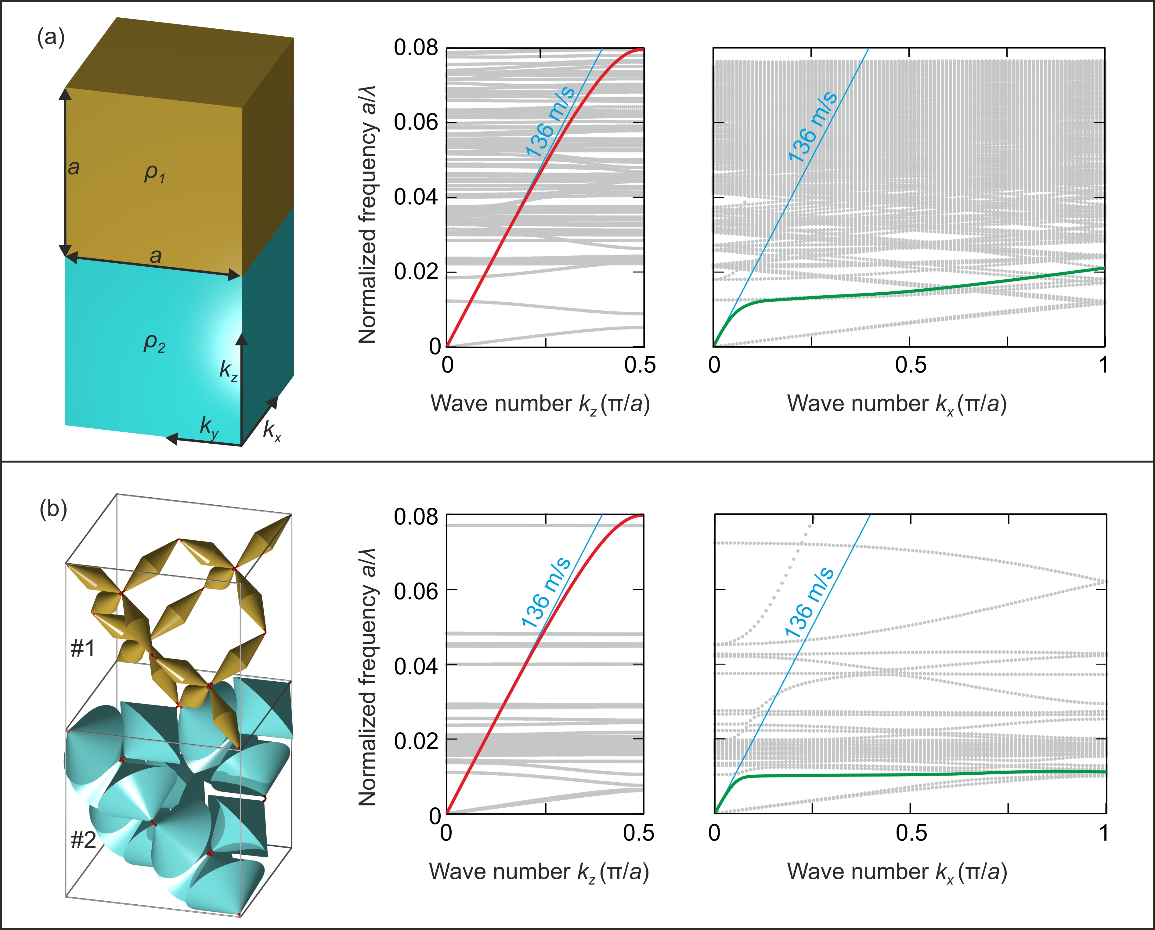
Intuitively, if the shear was actually zero, one would get a fast compression mode in the low-mass-density layer and an additional independent slower one in the high-mass-density layer. However, as the shear is small but not zero, the high-mass-density layer is pulled back by the shear with respect to the low-mass-density layer (and vice versa). This small shear force together with the large mass of the high-mass-density layer leads to a mass-and-spring system with low eigenfrequency. For excitation above this resonance frequency, this mass reacts with 180 degrees phase shift, which can be described as an effectively negative mass density Kadic et al. (2013b). Altogether, one gets a different effective dynamic mass density for propagation in the laminate layer plane and perpendicular to it, respectively, i.e., the scalar isotropic mass density of the metamaterial turns into an anisotropic mass density tensor for the laminate. One should be aware though that this anisotropy can be exploited only over a fairly small frequency region. This limitation holds true for any structure exhibiting a resonant dynamic mass density (tensor), because the mass density of an elastic solid always approaches the isotropic static case, , in the true long-wavelength limit (see discussion above)—just like the magnetic permeability of electromagnetic metamaterials approaches in the static limit Pendry et al. (1999).
In conclusion, we have introduced modified pentamode metamaterials and laminate heterostructures made thereof. These structures provide enhanced flexibility for molding the flow of longitudinal acoustic phonons in mechanics similar to that for photons in magneto-dielectric metamaterials in optics. Corresponding polymeric three-dimensional unit cells can be fabricated with current state-of-the-art optical laser lithography.
Acknowledgements.
We thank the Hector Fellow Academy for support. We also acknowledge support by the Deutsche Forschungsgemeinschaft (DFG), the State of Baden-Württemberg, and the KIT via the DFG-Center for Functional Nanostructures (CFN) through projects A 1.4 and A 1.5 and via the Karlsruhe School of Optics Photonics (KSOP).M.K. and T.B. contributed equally to this work.
References
- Nag (2005) P. Nag, Engineering Thermodynamics (Tata McGraw Hill, 2005).
- García-Chocano et al. (2012) V. M. García-Chocano, D. Torrent, and J. Sanchez-Dehesa, Appl. Phys. Lett. 101, 084103 (2012).
- Ashby (2010) M. Ashby, Materials Selection in Mechanical Design (Elsevier Science, 2010).
- Zheng et al. (2014) X. Zheng, H. Lee, T. H. Weisgraber, M. Shusteff, J. DeOtte, E. B. Duoss, J. D. Kuntz, M. M. Biener, Q. Ge, J. A. Jackson, S. O. Kucheyev, N. X. Fang, and C. M. Spadaccini, Science 344, 1373 (2014).
- Kistler (1987) S. S. Kistler, Nature 127, 741 (1987).
- Tillotson and Hrubesh (1992) T. Tillotson and L. Hrubesh, J. Non-Cryst. Solids 145, 44 (1992).
- Schaedler et al. (2011) T. A. Schaedler, A. J. Jacobsen, A. Torrents, A. E. Sorensen, J. Lian, J. R. Greer, L. Valdevit, and W. B. Carter, Science 334, 962 (2011).
- Mecklenburg et al. (2012) M. Mecklenburg, A. Schuchardt, Y. K. Mishra, S. Kaps, R. Adelung, A. Lotnyk, L. Kienle, and K. Schulte, Adv. Mater. 24, 3486 (2012).
- Jang et al. (2013) D. Jang, L. R. Meza, F. Greer, and J. R. Greer, Nat. Mater. 12, 893 (2013).
- Bauer et al. (2014) J. Bauer, S. Hengsbach, I. Tesari, R. Schwaiger, and O. Kraft, Proc. Natl. Acad. Sci. (2014), 10.1073/pnas.1315147111.
- Milton et al. (2006) G. W. Milton, M. Briane, and J. R. Willis, New J. Phys. 8, 248 (2006).
- Norris (2008) A. N. Norris, Proc. R. Soc. London, Ser. A 464, 2411 (2008).
- Brun et al. (2009) M. Brun, S. Guenneau, and A. B. Movchan, Appl. Phys. Lett. 94, 061903 (2009).
- Olsson and Wall (2011) P. Olsson and D. J. N. Wall, Inverse Probl. 27, 045010 (2011).
- Norris and Parnell (2012) A. N. Norris and W. J. Parnell, P. Roy. Soc. A-Math. Phy. 468, 2881 (2012).
- Norris et al. (2013) A. N. Norris, F. A. Amirkulova, and W. J. Parnell, Math. Mech. Solids 0, 1 (2013).
- Craster and Guenneau (2013) R. V. Craster and S. Guenneau, Acoustic Metamaterials, Springer S. Mate., Vol. 166 (Springer Netherlands, 2013).
- Diatta and Guenneau (2014) A. Diatta and S. Guenneau, Appl. Phys. Lett. 105, 021901 (2014).
- Scandrett et al. (2010) S. C. Scandrett, J. E. Boisvert, and T. R. Howarth, J. Acoust. Soc. Am. 127, 2856 (2010).
- Cipolla et al. (2011) J. Cipolla, N. Gokhale, A. N. Norris, and A. Nagy, J. Acoust. Soc. Am. 130, 2332 (2011).
- Pendry et al. (2006) J. B. Pendry, D. Schurig, and D. R. Smith, Science 312, 1780 (2006).
- Leonhardt (2006) U. Leonhardt, Science 312, 1777 (2006).
- Cummer et al. (2008) S. A. Cummer, B.-I. Popa, D. Schurig, D. R. Smith, J. Pendry, M. Rahm, and A. Starr, Phys. Rev. Lett. 100, 024301 (2008).
- Milton and Cherkaev (1995) G. W. Milton and A. V. Cherkaev, J. Eng. Mater. Technol. 117, 483 (1995).
- Sigmund (1995) O. Sigmund, Mech. Mater. 20, 351 (1995).
- Kadic et al. (2012) M. Kadic, T. Bückmann, N. Stenger, M. Thiel, and M. Wegener, Appl. Phys. Lett. 100, 191901 (2012).
- Kadic et al. (2013a) M. Kadic, R. Schittny, T. Bückmann, and M. Wegener, New J. Phys. 15, 023029 (2013a).
- Schittny et al. (2013) R. Schittny, T. Bückmann, M. Kadic, and M. Wegener, Appl. Phys. Lett. 103, 231905 (2013).
- Mejica and Lantada (2013) G. F. Mejica and A. D. Lantada, Smart Mater. Struct. 22, 115013 (2013).
- Spadoni et al. (2014) A. Spadoni, R. Höhler, S. Cohen-Addad, and V. Dorodnitsyn, J. Acoust. Soc. Am. 135, 1692 (2014).
- Layman et al. (2013) C. N. Layman, C. J. Naify, T. P. Martin, D. C. Calvo, and G. J. Orris, Phys. Rev. Lett. 111, 024302 (2013).
- Von Mises (1913) R. Von Mises, Nachr. Ges. Wiss. Göttingen , 582 (1913).
- Bückmann et al. (2014a) T. Bückmann, M. Thiel, M. Kadic, R. Schittny, and M. Wegener, Nat. Commun. 5, 4130 (2014a).
- Martin et al. (2012) A. Martin, M. Kadic, R. Schittny, T. Bückmann, and M. Wegener, Phys. Rev. B 86, 155116 (2012).
- Mei et al. (2007) J. Mei, Z. Liu, W. Wen, and P. Sheng, Phys. Rev. B 76, 134205 (2007).
- Bückmann et al. (2014b) T. Bückmann, R. Schittny, M. Thiel, M. Kadic, G. W. Milton, and M. Wegener, New J. Phys. 16, 033032 (2014b).
- Kadic et al. (2013b) M. Kadic, T. Bückmann, R. Schittny, and M. Wegener, Rep. Prog. Phys. 76, 126501 (2013b).
- Milton (2002) G. W. Milton, The Theory of Composites (Cambridge University Press, 2002).
- Pendry et al. (1999) J. Pendry, A. J. Holden, D. J. Robbins, and W. J. Stewart, IEEE T. Microw. Theory 47, 2075 (1999).