Further author information: (Send correspondence to H.L.M.)
H.L.M.: hermanm@space.mit.edu,
Telephone: 1 617 253 8573
The Use of Laterally Graded Multilayer Mirrors for Soft X-ray Polarimetry
Abstract
We present continued development of laterally graded multilayer mirrors (LGMLs) for a telescope design capable of measuring linear X-ray polarization over a broad spectral band. The multilayer-coated mirrors are used as Bragg reflectors at the Brewster angle. By matching to the dispersion of a spectrometer, one may take advantage of high multilayer reflectivities and achieve modulation factors over 50% over the entire 0.2-0.8 keV band. In Phase II of the polarimetry beam-line development, we demonstrated that the system provides 100% polarized X-rays at 0.525 keV (Marshall et al. 2013). Here, we present results from phase III of our development, where a LGML is used at the source and laterally manipulated in order to select and polarize X-rays from emission lines for a variety of source anodes. The beam-line will then provide the capability to test polarimeter components across the 0.15-0.70 keV band. We also present plans for a suborbital rocket experiment designed to detect a polarization level of better than 10% for an active galactic nucleus.
keywords:
X-ray, polarimeter, astronomy, multilayer, mirror, grating1 INTRODUCTION
We continue our investigation and laboratory work to develop a soft X-ray polarimeter based on Bragg reflection from multilayer-coated optics. Marshall (2007[1]) described a method using transmission gratings to disperse the incoming X-rays so that the dispersion is matched to laterally graded multilayer (ML) coated reflectors. An extension of this approach was suggested by Marshall (2008[2]) that can be used with larger missions such as the AXSIO or AEGIS. Some potential scientific investigations that would be possible with a soft X-ray polarimeter were described earlier and include testing the synchrotron nature of quasar jet emission and models of neutron star atmospheres[3, 4].
The laboratory work was initiated in order to demonstrate polarization measurements using gratings and laterally graded multilayer coated mirrors (LGMLs) for eventual use in a flight design. Here, we describe the first results from Phase III of our development work along with reflectivity data for a new LGML. A description of a design for a suborbital rocket flight is given in §4, comparable to that described in Paper I. The experiment’s minimum detectable polarization (MDP) is expected to be about 10% when observing a bright blazar such as Mk 421.
2 The MIT Polarimetry Beamline
We recommissioned the X-ray grating evaluation facility (X-GEF), a 17 m beamline that was developed for testing transmission gratings fabricated at MIT for the Chandra project[5]. The project development is proceeding in four distinct phases, of which two have been completed. In Phase I, we set up the polarized X-ray source at one energy (0.525 keV) and aligned it so that the beam was uniform at the detector and its intensity did not vary significantly with rotation angle. In Phase II, we added a ML coated mirror to the detector end of the system, reoriented the detector to face 90∘ to the beamline, and demonstrated that the source produced nearly 100% polarized X-rays. Results from phases I and II were reported by Marshall et al. (2013[6], hereafter Paper I).
We are now in Phase III, where we replaced the source ML coated mirror with a LGML. In Phase IV, we will insert a diffraction grating in order to disperse the polarized input onto an LGML in the detector chamber. In addition, we will test LGMLs with improved reflectivities and with larger ML coating periods in order to demonstrate that they can be used in a flight system, such as the one described in §4.
2.1 Polarimetry Beamline Phase III
With MKI technology development funding, we adapted the source to produce polarized X-rays at the O-K line (0.525 keV)[7]. A five-way chamber was added to house the polarized source multilayer (ML) mirror. The mirror and a twin were provided by Reflective X-ray Optics (RXO), with a coating consisting of 200 layers of 5.04Å of W alternating with 11.76 Å of B4C. The wavelength, , of the Bragg peak for a periodic ML coating is given by , where Å is the average layer thickness, and is the graze angle (measured from the surface). The detector is a front-side illuminated CCD.
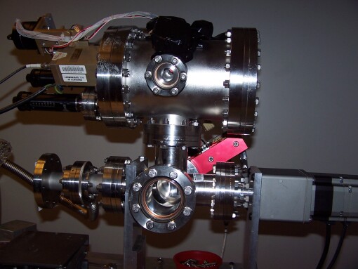
With funding from a MIT Kavli Investment grant, we started Phase III, where the goal was to develop, test, and install a laterally graded ML coated mirror (LGML) in the source mirror chamber. A pair of LGMLs were fabricated by RXO, consisting of 80 bilayers of W and B4C on highly polished Si wafers. The multilayer period was varied linearly along the 47 mm length of the substrate in order to reflect and polarize X-rays from 17Å to 73Å (170 to 730 eV). Fig. 1 shows a picture of the source hardware and Fig. 2 shows details.
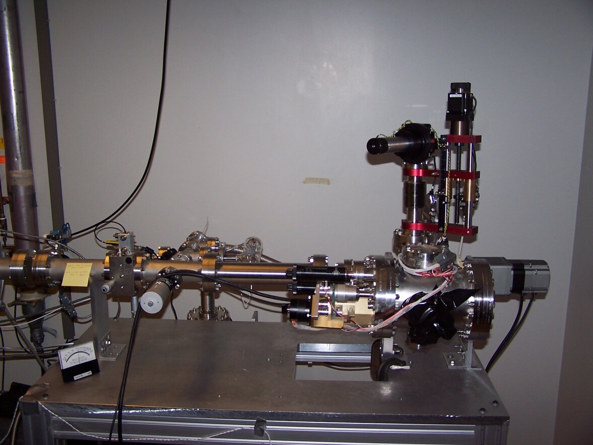
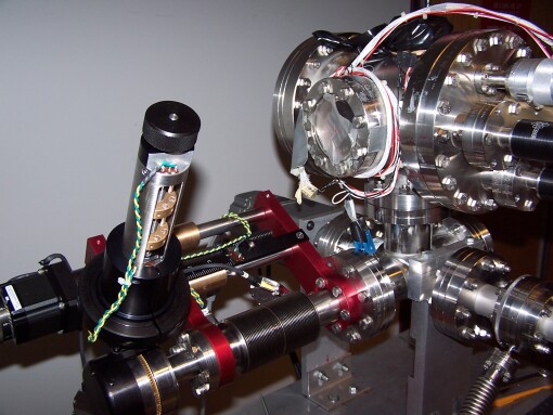
The W/B4C LGML is now mounted to the shaft of the motor-controlled rotational manipulator so that the axis of the shaft is centered on the long axis of the LGML’s surface. The shaft’s rotation angle is controllable to 0.01∘. It is mounted on a linear bellows with a 100 mm travel that is computer-controlled to an accuracy of 0.01 mm.
The LGML mirror was aligned by setting up a laser in the detector chamber about 16 m from the X-ray source and pointed through the square collimating aperture to the polarizing mirror, thus defining the beamline optical axis. This procedure was developed and implemented successfully in phase I (see Paper I). The mirror readily reflects laser light, so it was rotated to be perpendicular to the laser beam, in order to reflect the laser beam back to the collimating aperture. The mirror holder has two adjustment screws (one can be seen in Fig. 2, center), which were adjusted to ensure that the reflected laser beam was centered on the collimating aperture, even as the mirror chamber was rotated. In this manner, the mirror’s axis was aligned to the beamline axis to within 1 cm along an 8.5 m length, for an accuracy of about radians. Being aligned while oriented 90∘ to the beamline, the LGML was then rotated precisely 45∘ for operation, using the rotational manipulator.
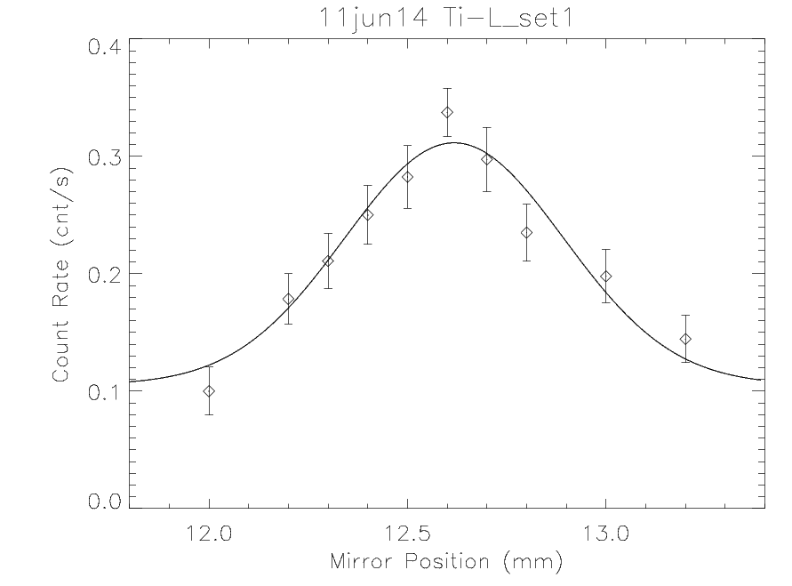
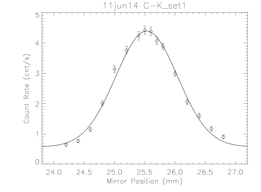
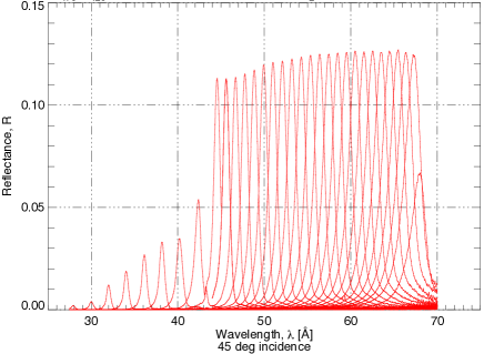
The location was defined as the edge of the LGML, and increases along its length. Operationally, this position was placed at the center of the beamline to set the linear manipulator’s zero point. The alignment laser was used, providing a zero point that matched to within about 0.5 mm. The location of the Bragg peak for wavelength was computed from ALS measurements to be , where 12.076 Å and 1.2398 Å mm-1. Inverting, the predicted locations of the Ti-L and C-K lines were expected to be found at 12.375 mm and 26.36 mm, respectively. Scans of the linear manipulator are shown in Fig. 3.
Given that the CCD is front-side illuminated, the C-K line is gratifyingly bright and the events were readily distinguished from background events using pulse height discrimination. Optical light from the source filament was found to be a major contributor to the background and was reduced by placing an aperture stop made from aluminum foil between the source LGML and the X-ray source itself.
The widths of the response curves in Fig. 3 are a the result of a combination of the breadth of the Bragg reflectivity curve of the LGML and of the intrinsic width of the C-K line or the Ti-L complex. From ALS measurements, the FWHM of the Bragg peak is about 1.3% of the peak wavelength, corresponding to a FWHM of 0.29 mm (0.47 mm) for Ti-L (C-K). The observed FWHM values are 0.65 mm and 1.20 mm for Ti-L and C-K, respectively, leaving a contribution of 0.58 mm and 1.10 mm due to the intrinsic widths of the emission features. Translated to wavelength and energy units gives 0.72 Å and 1.37 Å or 11.9 eV and 8.5 eV for the FWHMs of the Ti-L and C-K emission.
2.2 Polarimetry Beamline Phase IV
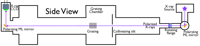
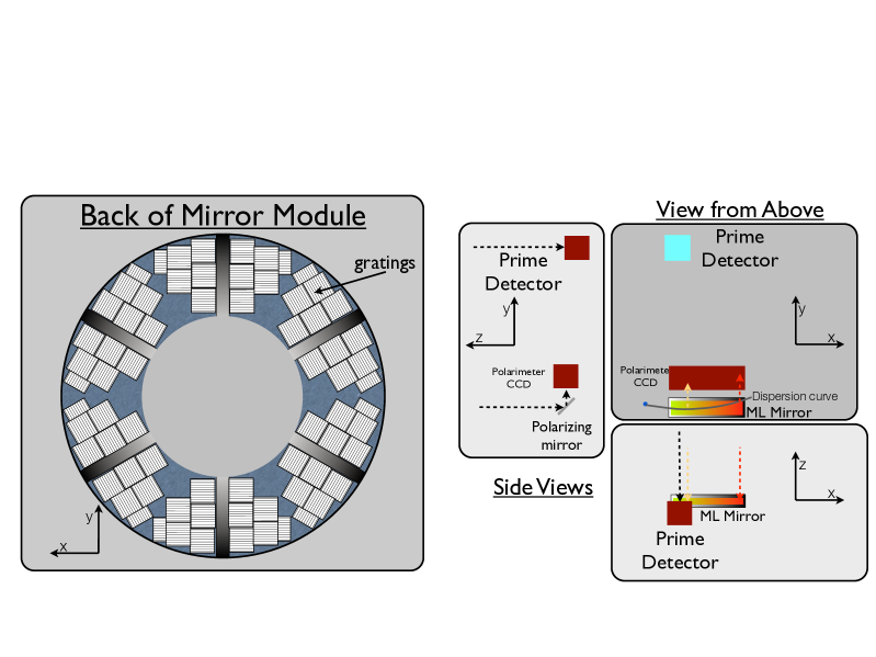
With funding from the NASA Astrophysics Research and Analysis (APRA) program, we will soon move to Phase IV, where the goals are 1) to improve the reflectivities of LGMLs by trying new material combinations and 2) show that a grating-LGML combination can measure polarization over wide range of energies, thus prototyping a design that could be used for a flight system. See Fig. 4 for a schematic of the Phase IV configuration.
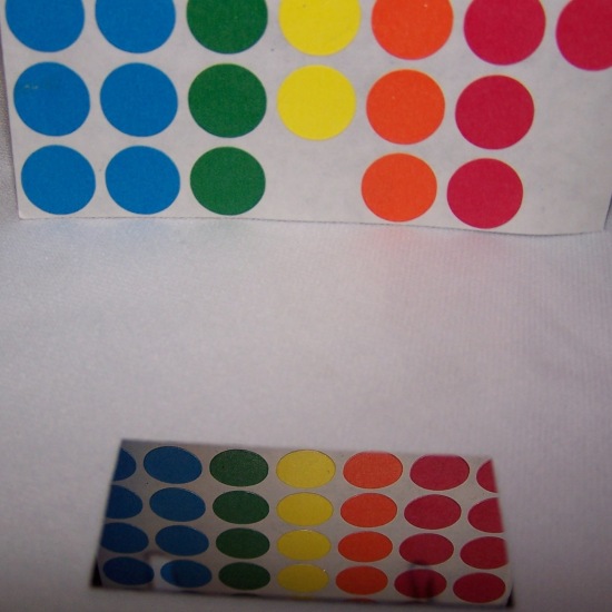
We have begun work to improve LGML reflectivities using different ML compositions for specific wavelength regions. Figure 5 shows results from ALS testing of the first few single-period MLs involving C and Cr or a CoCr alloy, shown in Fig. 6. The C/CoCr reflectivities to s-polarization approach 20% in the 45-65 Å range. These reflectivites are substantially better than the 2-5% values currently available in the W/B4C LGMLs (Paper I). ML coating process adjustments will be varied in order to improve the reflectivities below 45 Å.

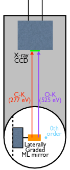
The main advance in Phase IV will be to use gratings to disperse the X-rays to the LGML in the detector chamber. The dispersion of the grating is given by the grating equation: , where is the grating period, is the grating order of interest (which we take to be ) and is the dispersion angle. Defining to be the horizontal direction in Fig. 4(right) and defining to be where the 0th order lands at the plane of the LGML, then we match the LGML’s Bragg peak to the grating dispersion by setting , where is the distance from the grating to the LGML, giving as the multilayer period. As long as is linear, the LGML can be placed at distance from the grating to reflect X-rays of arbitrary wavelengths, within the physical limitation of the LGML. The current LGMLs have gradients ddÅ/mm, giving ddÅ/mm, which is matchable by gratings made for the Chandra Low Energy Transmission Grating (LETG) Spectrometer [8] with Å for m. We have four LETG facets on loan from MPE (courtesy P. Predehl) that will be mounted in the grating chamber for this purpose. When completed, the Phase IV configuration emulates a flight system from the point of the beam line from the rotating flange down to the detector. By varying the linear position of the LGML mounted in the source chamber, we will be able to generate 100% polarized X-rays over the 17-73 Å (170 to 730 eV) range and rotate the polarization angle to confirm modulation curves such as obtained in Phase II (see Paper I).
3 Moving the Polarimetry Beamline
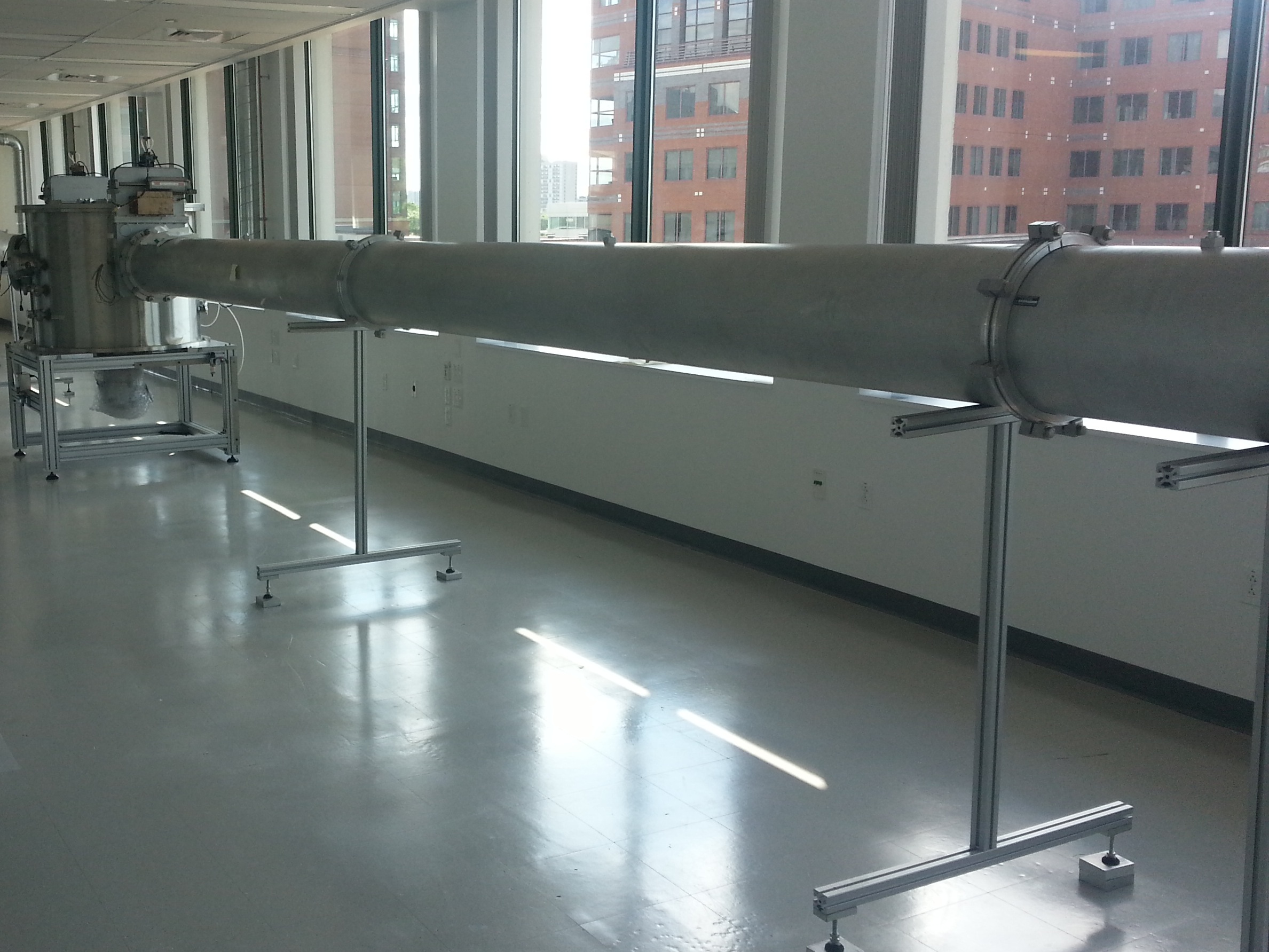
Due to the termination of the lease for the floor occupied by the facility for the past twenty years, the beamline was moved to a newly leased floor of an adjacent building, designated NE83. The beamline was disassembled and is in the process of reassembly. Fig. 7 shows the grating chamber and the source side beam pipe after initial leveling but before reconnecting wiring. After alignment, the first scientific tests will be to repeat the initial Phase III tests using the Ti-L and C-K lines.
4 A Soft X-ray Polarizing Spectrometer
The basic design of a polarizing spectrometer was outlined by Marshall (2008 [2]). For this paper, we examine the approach that could be applied to a suborbital rocket experiment. Figure 8 shows a possible schematic for a suborbital mission using blazed gratings such as the Critical Angle Transmission (CAT) gratings under development at MIT[9, 10] or reflection gratings used in an off-plane configuration[11]. Sampling at least 3 position angles is required in order to measure three Stokes parameters (I, Q, U) uniquely, so one would require at least three separate detector systems (one of which could be just for 0th order) with accompanying multilayer-coated flats or that the rocket rotate during the observations (which is expected anyway, to take out systematic effects).
The system design consists of a mirror system with an assumed effective area of 350 cm2 below 1 keV, backside-illuminated CCD detectors like those on Chandra with thin directly deposited optical blocking filters, and CAT or reflection gratings blazed to maximize efficiency at 300 eV. We have also computed effective areas using LETGs [8]. For ML coating reflectivities, we used values that have been achieved in the lab for single-period MLs used at 45∘ and interpolated using comparable theoretical models.
The effective area estimate can be used to predict the minimum detectable polarization (MDP) for a potential target. Extragalactic sources such as the BL Lac object Mk 421 are expected to be highly polarized in the soft X-ray band. We use the same expected spectrum as assumed in Paper I. In a 500 s observation of Mk 421, this instrument could detect polarizations of 3.9% using CAT or reflection gratings or 6.5% using LETGs. LGMLs with the achievable reflectivities have not yet been fabricated, so we computed the MDPs for reflectivities as measured by the ALS for the W/B4C LGML made by RXO. Interpolating using the Bragg peak reflectivities at the measured energies gives MDPs of 11.4% for CAT or reflection gratings, and 16% using LETGs. Continued development of LGMLs are expected to bring these MDPs down below 10%.
Acknowledgements.
We are very grateful for the assistance and support provided by Steve Kissel and Beverly LaMarr in providing, operating, and modifying the CCD detector system. Support for this work was provided by the National Aeronautics and Space Administration through grant NNX12AH12G and by Research Investment Grants from the MIT Kavli Institute.References
- [1] Marshall, H. L., “A soft x-ray polarimeter designed for broadband x-ray telescopes,” in [Optics for EUV, X-Ray, and Gamma-Ray Astronomy III. Edited by O’Dell, Stephen L.; Pareschi, Giovanni. Proceedings of the SPIE, Volume 6688, pp. 66880Z (2007). ], Presented at the Society of Photo-Optical Instrumentation Engineers (SPIE) Conference 6688 (Sept. 2007).
- [2] Marshall, H. L., “Polarimetry with a soft x-ray spectrometer,” in [Society of Photo-Optical Instrumentation Engineers (SPIE) Conference Series ], Society of Photo-Optical Instrumentation Engineers (SPIE) Conference Series 7011 (Aug. 2008).
- [3] Marshall, H. L., Murray, S. S., Chappell, J. H., Schnopper, H. W., Silver, E. H., and Weisskopf, M. C., “Realistic, inexpensive, soft x-ray polarimeter and the potential scientific return,” in [Polarimetry in Astronomy. Edited by Silvano Fineschi . Proceedings of the SPIE, Volume 4843, pp. 360-371 (2003). ], Fineschi, S., ed., Presented at the Society of Photo-Optical Instrumentation Engineers (SPIE) Conference 4843, 360–371 (Feb. 2003).
- [4] Marshall, H. L., Heilmann, R. K., Schulz, N. S., and Murphy, K. D., “Broadband soft x-ray polarimetry,” in [Society of Photo-Optical Instrumentation Engineers (SPIE) Conference Series ], Society of Photo-Optical Instrumentation Engineers (SPIE) Conference Series 7732 (July 2010).
- [5] Dewey, D., Humphries, D. N., McLean, G. Y., and Moschella, D. A., “Laboratory calibration of x-ray transmission diffraction gratings,” in [Proc. SPIE Vol. 2280, p. 257-271, EUV, X-Ray, and Gamma-Ray Instrumentation for Astronomy V, Oswald H. Siegmund; John V. Vallerga; Eds. ], Siegmund, O. H. and Vallerga, J. V., eds., Presented at the Society of Photo-Optical Instrumentation Engineers (SPIE) Conference 2280, 257–271 (Sept. 1994).
- [6] Marshall, H. L., Schulz, N. S., Remlinger, B., Gentry, E. S., Windt, D. L., and Gullikson, E. M., “Progress toward a soft x-ray polarimeter,” in [Society of Photo-Optical Instrumentation Engineers (SPIE) Conference Series ], Society of Photo-Optical Instrumentation Engineers (SPIE) Conference Series 8861 (Sept. 2013).
- [7] Murphy, K. D., Marshall, H. L., Schulz, N. S., Jenks, K. P., Sommer, S. J. B., and Marshall, E. A., “Soft x-ray polarimeter laboratory tests,” in [Society of Photo-Optical Instrumentation Engineers (SPIE) Conference Series ], Society of Photo-Optical Instrumentation Engineers (SPIE) Conference Series 7732 (June 2010).
- [8] Predehl, P., Braeuninger, H. W., Brinkman, A. C., Dewey, D., Drake, J. J., Flanagan, K. A., Gunsing, T., Hartner, G. D., Juda, J. Z., Juda, M., Kaastra, J. S., Marshall, H. L., and Swartz, D. A., “X-ray calibration of the AXAF Low Energy Transmission Grating Spectrometer: effective area,” in [Society of Photo-Optical Instrumentation Engineers (SPIE) Conference Series ], Hoover, R. B. and Walker, A. B., eds., Society of Photo-Optical Instrumentation Engineers (SPIE) Conference Series 3113, 172–180 (July 1997).
- [9] Heilmann, R. K., Ahn, M., Gullikson, E. M., and Schattenburg, M. L., “Blazed high-efficiency x-ray diffraction via transmission through arrays of nanometer-scale mirrors,” Opt. Express 16(12), 8658–8669 (2008).
- [10] Heilmann, R. K., Ahn, M., Bautz, M. W., Foster, R., Huenemoerder, D. P., Marshall, H. L., Mukherjee, P., Schattenburg, M. L., Schulz, N. S., and Smith, M., “Development of a critical-angle transmission grating spectrometer for the International X-Ray Observatory,” in [Society of Photo-Optical Instrumentation Engineers (SPIE) Conference Series ], Society of Photo-Optical Instrumentation Engineers (SPIE) Conference Series 7437 (Aug. 2009).
- [11] McEntaffer, R., DeRoo, C., Schultz, T., Gantner, B., Tutt, J., Holland, A., O’Dell, S., Gaskin, J., Kolodziejczak, J., Zhang, W. W., Chan, K.-W., Biskach, M., McClelland, R., Iazikov, D., Wang, X., and Koecher, L., “First results from a next-generation off-plane X-ray diffraction grating,” Experimental Astronomy 36, 389–405 (Aug. 2013).