A compact ultra-clean system for deploying radioactive sources inside the KamLAND detector
Abstract
We describe a compact, ultra-clean device used to deploy radioactive sources along the vertical axis of the KamLAND liquid-scintillator neutrino detector for purposes of calibration. The device worked by paying out and reeling in precise lengths of a hanging, small-gauge wire rope (cable); an assortment of interchangeable radioactive sources could be attached to a weight at the end of the cable. All components exposed to the radiopure liquid scintillator were made of chemically compatible UHV-cleaned materials, primarily stainless steel, in order to avoid contaminating or degrading the scintillator. To prevent radon intrusion, the apparatus was enclosed in a hermetically sealed housing inside a glove box, and both volumes were regularly flushed with purified nitrogen gas. An infrared camera attached to the side of the housing permitted real-time visual monitoring of the cable’s motion, and the system was controlled via a graphical user interface.
keywords:
Large detector systems for particle and astroparticle physics , Detector alignment and calibration methods (lasers, sources, particle-beams) , Scintillators, scintillation and light emission processes (solid, gas and liquid scintillators)PACS:
29.40.Mc , 06.20.fb , 29.25.Rm , 14.60.Pq , 26.65.+t1 Introduction
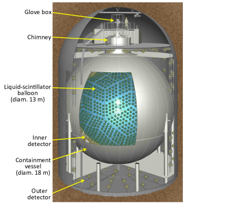
The Kamioka Liquid-scintillator Anti-Neutrino Detector (KamLAND) is a physics experiment located 1 km underground in a mine near Kamioka-cho, Gifu, Japan. KamLAND (Fig. 1) contains 1 kton of ultra-pure liquid scintillator (LS) which serves as both the target and detecting medium for neutrino interactions. A detailed description of the detector is given in [1].
KamLAND was commissioned in 2001 and used primarily to study the flux and energy spectrum of electron anti-neutrinos emitted by surrounding nuclear reactors. The experiment provided convincing evidence that anti-neutrinos are massive particles that undergo flavor oscillations during propagation and it yielded precision determinations of the neutrino oscillation parameters [2, 3, 4, 5]. In addition, KamLAND was the first experiment to report evidence of geoneutrinos, which are anti-neutrinos produced by radioactivity in the Earth’s interior [6]. A subsequent measurement by KamLAND indicated that decay of radiogenic isotopes accounts for roughly half of the heat flux emanating from the Earth’s interior; this was the first geoneutrino result to constrain geothermal models [7].
From May 2007 to February 2009 the KamLAND Collaboration conducted an intensive campaign to further purify the detector’s LS, with the goal of enabling detection of solar neutrinos from 7Be decay in order to test aspects of the Standard Solar Model [8, 9, 10]. Purification was necessary because monoenergetic 7Be solar neutrinos are detected via elastic scattering by electrons, a method that requires much lower backgrounds than the delayed-coincidence technique used to detect higher-energy reactor anti-neutrinos. In order to render a 7Be solar neutrino measurement possible, the already low concentrations in the LS of certain unwanted, long-lived isotopes—primarily 40K, 85Kr, and 210Pb—had to be reduced by several orders of magnitude.
Detector calibrations—in which radioactive sources of known energy are deployed to precise positions inside the LS in order to determine the timing of the surrounding photomultiplier tubes, the uncertainty in reconstructed event positions, and the detector’s energy response—were identified as a potential threat to the radiopurity improvements expected from LS purification. There was strong evidence that the existing calibration systems had introduced contamination (primarily 222Rn, a highly mobile noble gas which generates the problematic long-lived daughter 210Pb) in amounts that would be unacceptable under the new experimental circumstances [11]. Given that routine calibrations would be essential to the collection of high-quality data, the collaboration decided to implement a new, ultra-clean source deployment system for use following the LS purification campaign. The new calibration system, nicknamed “MiniCal” due to its compact size, is the subject of this paper.
2 System design
2.1 Requirements and constraints
The primary challenge in designing and building MiniCal lay in meeting oft-competing requirements regarding its size, cleanliness, and capabilities.
-
1.
Compact size: Every calibration system used in KamLAND has been installed inside a glove box atop the detector’s chimney (Fig. 1). Access to the chimney and detector was possible via an 8-inch flanged opening in the floor of the glove box. During normal data taking, detector access was blocked by two hermetically sealing gate valves located in series along the chimney’s column, and the glove box was typically overpressured with nitrogen gas to prevent intrusion of contaminants, primarily radon.
Prior to MiniCal, hardware from a previous, full-detector-volume calibration system [11] occupied a large fraction of the space in the glove box. We wanted to leave that system intact to preserve the possibility of making future off-axis deployments, so MiniCal was designed to fit in the small space available beneath it (Fig. 2).
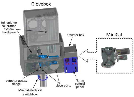
Figure 2: Drawings of the MiniCal calibration device alone (right) and installed inside the glove box atop the KamLAND detector (left). MiniCal is highlighted in blue in the latter for visibility. Space inside the glove box was limited due to the continued presence of hardware from the previous, full-detector-volume calibration system. It should be mentioned that the full-volume calibration system could not be deployed while MiniCal was installed because the latter blocked access to the detector.
The largest components of MiniCal also needed to be small enough to fit inside the glove box’s 1-cubic-foot transfer box so that the new system could be moved into the glove box piecemeal and assembled inside. And despite its small size, MiniCal needed to be amenable to servicing via the glove box’s thick Viton gloves.
-
2.
Materials and cleanliness: The KamLAND LS is a highly active, radiopure solvent composed primarily of dodecane and pseudocumene [1]. All MiniCal components to be submerged in the LS had to be ultra-clean and possess low intrinsic radioactivity (so as to avoid contaminating the detector), and they had to be made of materials that would not be damaged by the LS or degrade its optical purity. The MiniCal hardware in the glove box needed to be capable of withstanding prolonged exposure to LS vapors without suffering negative effects or emitting contaminants.
The two preceding calibration systems had used large-gauge wire rope and wide-ribbon woven-nylon cables, respectively, and the large surface areas of these materials tended to collect radon and radon daughters during idle periods and then transport them into the detector during deployments. To reduce this problem—and also to meet the stringent spatial constraints—it was necessary that MiniCal utilize a small-gauge cable of some kind. We also elected to enclose the apparatus within its own hermetically sealed housing to provide a secondary barrier against radon intrusion.
-
3.
Accuracy and precision: The KamLAND vertex reconstruction algorithm is tuned to minimize the difference between the nominal position of a deployed source and the mean of its corresponding event distribution, for a number of different source positions. Consequently, a systematic error in the positioning of sources—even if small compared to the detector resolution of 12 cm/—can introduce a vertex reconstruction bias that significantly increases the systematic uncertainty in the fiducial volume estimate and thus negatively impacts the final physics result [11]. Prior to MiniCal, the systematic error due to vertex reconstruction bias along the detector’s central vertical axis (z-axis) was 2 cm. We aimed to strongly limit the new deployment system’s contribution to this error by making it capable of placing a source within mm of any point along the z-axis, a length spanning 19 m from the glove box to the bottom of the LS balloon.
2.2 Materials selection and radioassay
The KamLAND LS is a mixture of 20% pseudocumene, 80% dodecane, and 1.36 g/l of the fluor PPO. Pseudocumene is a highly active organic solvent which can damage the structural integrity of many materials, so care had to be taken when choosing components for the calibration system.
The MiniCal components to be submerged in the LS or exposed to its vapors were made almost exclusively from materials that had been identified in past tests by the KamLAND collaboration [11] and others [12] as being chemically compatible with the LS—namely, 304 and 316 stainless steel, gold, titanium, nylon, Teflon, Viton, and quartz. Only 416 stainless steel, whose magnetic properties were needed for one small component which would be submerged (see Sec. 2.5), required new examination. LS soak and light attenuation tests on 416 samples indicated the component would not negatively affect the LS, or vice versa. All other MiniCal components to be submerged in the LS were made of 304 or 316 stainless steel.
To guard against introducing radioactive contaminants into the KamLAND detector, strict protocols were followed in cleaning and certifying the parts of the calibration system that would enter the detector volume or be exposed to LS vapors. All such parts were UHV cleaned according to a standard protocol employed at Lawrence Berkeley National Laboratory (LBNL) [13] and the system was preassembled and packaged in a class 10,000 clean room at LBNL before shipment to the experimental site. Items that were to be submerged in the LS, or that would come into direct contact with components to be submerged in the LS, underwent an additional cleaning and certification procedure [11] consisting of a series of heated ultrasonic cleanings in a weak solution of aqueous trace-metal-grade nitric acid and deionized water (0.2 mol/l). A 100-ml sample of the nitric solution was collected at the end of the final cleaning and counted using a surface Ge detector operated by the LBNL Low Background Facility [14]. No evidence of U, Th, or K contamination above the detector’s sensitivity limits was observed; the upper limits after a 30-day count were U mBq/kg, Th mBq/kg, and K mBq/kg, where kg refers to leachate mass.
2.3 Hardware
The basic concept for the MiniCal system is simple: it used a stepper motor to turn a spool of cable and thereby lower and raise a radioactive source along the z-axis of the KamLAND detector (Figure 3). The motion of the cable was measured by an encoded pulley located above the z-axis, enabling precise positioning of the source.
We elected to use a thin-gauge cable because compared to the alternatives (e.g., a chain or sprocketed cable) it offered the best combination of simplicity and cleanliness. The primary drawback was that great care had to be taken to prevent cable slippage on the encoded pulley, as that would have ruined positioning accuracy. The cable was made by Strand Products, Inc., from -inch-diameter, 719-stranded, 120-pound tensile wire rope that had been proof-loaded to 60% of its breaking strength to eliminate constructional stretch181818Our own dynamometer tests demonstrated that the breaking strength of the cable assemblies was approximately 100 pounds (45 kg).. This particular cable was selected for several reasons: it is composed entirely of T304 stainless steel, which is LS-compatible; it has a small diameter, which served to minimize both the amount of space it occupied when spooled and the amount of surface area that could collect contaminants; and its strand lay renders the cable very supple and allowed it to maintain good contact with the encoded z-axis pulley, which was machined from titanium to minimize its rotational inertia.
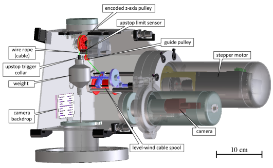
Each end of the cable terminated in a swaged bushing: one end was anchored to the spool, while the other end was attached to a free-hanging 0.55 kg weight which kept the cable under tension to ensure good contact with the encoded pulley. A captured, spring-loaded pin in the underside of the weight was used for easy attachment of different radioactive sources. The attachment mechanism was designed to be backwards-compatible with existing sources used with the previous calibration systems, requiring only that each source be fitted with an adaptor bolt.
The cable was wound on a custom spool modeled after a Penn GTO 220 level-wind fishing reel. This device contained a cable guide mechanically coupled to the spool’s rotation to wind cable evenly and compactly along the length of the spool. A small guide pulley located between the spool and the z-axis pulley prevented the side-to-side motion of the spooling cable from affecting its smooth passage over the z-axis pulley. The spool was turned by an Anaheim Automation 23MDSI integrated stepper motor performing 1600 steps/revolution.
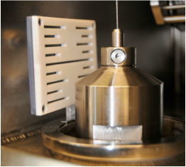
It had been observed that the previous KamLAND calibration system had introduced small amounts of radon into the LS, likely due to small leaks in the glove box that allowed ingress of ambient outside air. In order to provide an added barrier against radon intrusion, the MiniCal hardware was enclosed within a hermetically sealed housing (Figure 4) which was bolted to the 8-inch-diameter conflat flange welded to the floor of the KamLAND glove box (Figure 2).
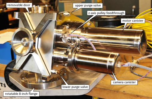
The housing was constructed by welding together jointed, -in.-thick stainless steel panels; afterwards it was electropolished to remove oxidation and passivate the surface. The interior was accessed through a 5.57.4 in.2 rectangular opening which faced the glove box’s gloves and was usually covered by a removable door. A Viton O-ring seated in the face of the door formed a seal against the housing when the the door’s hand-operated dial was cranked to press the two surfaces together. The housing sat atop a 1.8-in.-tall stand tube (3-in. OD, 2.75-in. ID) in order to provide clearance for inserting bolts into the 8-in. flange at its base.
The z-axis pulley was mounted to the housing’s ceiling on a movable stage which could be translated in two dimensions to center the hanging cable over the detector’s vertical axis. The centering procedure was performed at the time of installation with assistance from a cross-hair-engraved cover plate inserted in the stand-tube opening inside the MiniCal housing.
The floor of the housing was angled slightly so that LS brought up by the cable during deployments collected in its front. The accumulated LS—which was prevented from returning to the detector by a small collar around the stand-tube opening in the housing’s floor—was periodically drained through a manually operated Swagelok Whitey P-series stainless steel purge valve (with PTFE ball) mounted on the lower corner of the housing. This valve and an identical one located above it also functioned as vents during nitrogen gas purges of the MiniCal housing volume (see Sec. 3.1). The spring-loaded valves were bracketed by steel retaining arms to prevent them from being unscrewed to the point of disassembly.
In order to prevent the stepper motor from introducing contaminants or coming into contact with corrosive LS vapors, it was enclosed inside a leak-tight stainless steel canister attached to the side of the housing. The motor’s 1/4-in. driveshaft connected to the cable spool via an MDC Vacuum direct-drive rotary mechanical feedthrough.
An infrared camera provided real-time visual monitoring of the cable when the housing was sealed shut during deployment operations. Like the motor, the camera—an Allied Vision Technologies Guppy F-038B black-and-white, near-infrared, asynchronous Firewire digital camera with a Kowa Model LM25JC 2/3-in. machine vision lens—was enclosed in a sealed canister. The camera viewed the interior of the housing through a quartz window, with two Advanced Illumination SL4301 880-nm IR LED 5-volt spot lights attached to the underside of the camera providing illumination. Infrared imaging equipment was chosen because its operating spectrum lies above the 600 nm optical cutoff of the detector’s PMTs.
All MiniCal flanges were made of stainless steel and joined using titanium bolts to avoid galling. The bolts were tethered to prevent being dropped or lost during assembly and disassembly. The flanges did not rely on knife edges to form gas-tight seals; instead, they had been modified to employ seated Viton O-rings, based on a design developed at LBNL. This technique offers several advantages over conventional flange gasket seals, which are single-use and can be awkward to manipulate manually. A rotatable 8-in. flange was used for the base of the MiniCal housing to permit convenient alignment of the housing during installation. The camera canister contained the assembly’s lone quick flange, which was useful for providing prompt access to the camera during its initial tuning.
2.4 Motion control software
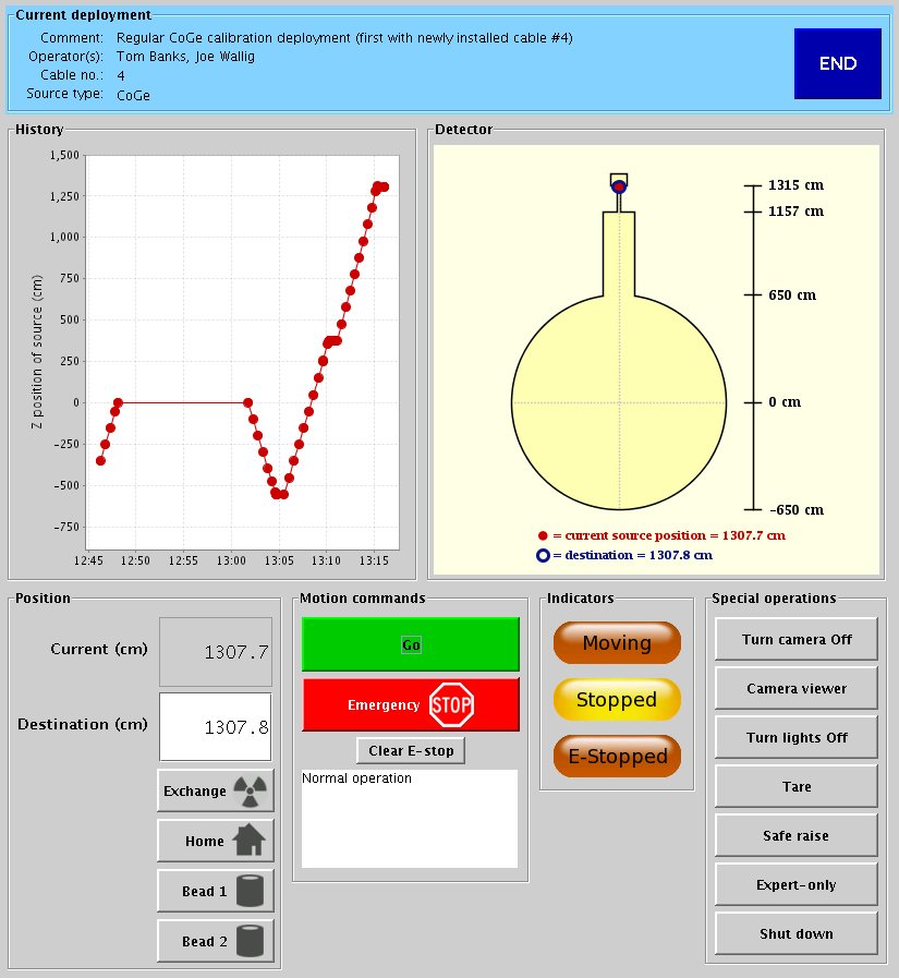
The MiniCal system was controlled and monitored using custom Java software running on a dedicated computer in an electronics room adjacent to the experiment. The software consisted of two independently functioning parts: a control side which communicated with the hardware, and a graphical user interface, or GUI (Figure 5), which communicated with the control side.
The two layers used the Java Remote Method Invocation protocol to communicate with each other in real time via changes to the values of a set of shared parameters. All system actions and parameter changes were logged to a PostgreSQL database.
The computer, a small-form-factor CappuccinoPC SlimPRO 620S, ran the open-source Fedora 9 Linux operating system. Three 9-pin serial ports were used to communicate with the stepper motor and encoders, and a Firewire port was used to communicate with the camera. The camera’s output was viewed using the software program Coriander. One of the serial ports was used to communicate with both the stepper motor and a Crouzet XT20 Millenium II+ programmable logic controller (PLC) which enabled software-controlled switching of power to the hardware. The PLC was used primarily to power the hardware on and off at system startup and shutdown, and to toggle power to the driveshaft safety brake and the IR lights during system operation.
The stepper motor’s rotation was measured by a US Digital E5D optical encoder which was read out by a US Digital AD4-B-D quadrature encoder counter. The motor’s revolutions could not be used to precisely determine cable payout, however, because the spool’s effective radius changed with the amount of spooled cable. Instead, cable payout (and hence the source’s position) was determined using the 3.6-cm-diameter titanium z-axis pulley, whose rotations were measured by a Renishaw RM22I non-contact rotary encoder with a resolution of 800 counts/revolution. The z-axis pulley was attached to a gold-plated rare-earth magnetic actuator which rotated inside the fixed stainless steel RM22I encoder housing; the encoder transmitted standard incremental quadrature output which was counted by another US Digital AD4-B-D unit. The pulley encoder electronics were enclosed inside a small hermetically sealed stainless steel box inside the MiniCal housing.
Because cable payout was controlled by the motor but measured by the z-axis pulley, the system generally had to iterate several motions before the deployed source reached the desired destination. When the user instructed the system to move the source to a new destination, the software computed a conservatively low estimate for the number of motor steps required and programmed this number into the motor. After the stepper motor executed the programmed index, the software compared the source’s current position against the destination and reprogrammed the motor as necessary. This process was repeated until the source converged to within 0.1 mm of its destination. The maximum translational speed of the cable during motion was restricted to 3.5 cm/s. The software took into account the fact that the amount of cable stretch varied slightly according to the weight of the attached source and the length of cable paid out191919We characterized the cable’s stretching behavior by measuring lengths of a similar cable when hung with loads of 0 kg, 0.5 kg, and 1.0 kg.. Most of the sources generated a maximum additional stretch of only 0.15 cm, though for one unusually heavy source the value was 0.6 cm.
The computer and power supplies were physically separated from the hardware by roughly 130 ft of distance and several barriers, chiefly the glove box and the MiniCal housing. To span the gap, the system utilized two intervening custom-built electronics boxes, one at each end, which contained devices for transmitting and processing data and power. The stepper motor and the two encoders communicated in RS485 protocol, which is well-suited for long-distance transmission; the motor and encoder signals were converted to RS232 protocol by a special adaptor and encoder counters, respectively, to communicate with the computer’s serial ports. The camera’s communications were transmitted using a Newnex FireNEX-CAT5 S400 extender pair, which converted the short-range IEEE 1394a (Firewire) protocol into a form suitable for long-distance transmission over standard cat5e ethernet cable at 400 Mbps. CeramTec sub-D and micro-D weldable hermetic feedthroughs were used to pass the electrical signals and power through the walls of the glove box and the MiniCal housing. Radiopurity considerations prohibit the use of solder in components exposed to the glove box environment, so all in-glove box electrical wiring was made from Teflon-coated wires and PEEK connectors using gold-plated crimped connections.
2.5 Safeguards
The MiniCal system possessed several built-in safety features, both in hardware and software, to prevent accidents or damage to either the detector or to the system itself.
-
•
An Anaheim Automation NEMA23 electromagnetic friction brake was attached to the driveshaft between the stepper motor and the spool. When electrical power was applied to the brake its electromagnet overcame the mechanical force from a spring, permitting the driveshaft to turn freely; when power was turned off the spring forced friction plates together, clamping the driveshaft in place. This type of “power-off” or “fail-safe” brake was desirable because it would immediately lock the driveshaft if power were lost.
-
•
A Polyclutch EFS 16 “slip-ease” clutch was connected to the driveshaft between the motor and the brake. In the unlikely event that the cable became caught, the clutch slipped at 4 kg weight equivalent, far below the cable’s approximately 45 kg breaking strength. Moreover, the motor itself slipped at roughly 4.5 kg weight equivalent, so the system was incapable of generating sufficient tension to break the cable.
-
•
An Automation Direct 12-mm round stainless steel inductive proximity sensor was installed just below the z-axis pulley to prevent the weight from being raised too high and colliding with the pulley superstructure. The upstop sensor was triggered by a small 416 stainless steel collar installed at the end of the cable just above the weight. When the sensor was triggered it sent a signal directly to the motor that blocked its ability to execute further upward motion. (The motor remained capable of downward motion.)
-
•
The cable length was chosen so that even at maximum extension an attached source could not come into contact with the bottom of the KamLAND balloon.
-
•
The GUI enforced restrictions on acceptable user-entered values to prevent the system from operating outside safe limits.
-
•
The software continuously monitored the status of the system, most notably the motion of the motor and z-axis pulley. If the software observed any motion when the system was supposed to be stopped, or if the driveshaft or pulley rotation speeds exceeded certain limits, or if there was any disagreement between the motor encoder and the z-axis pulley encoder (e.g., due to cable slippage), the software immediately stopped the motor and engaged the safety brake to prevent the cable spool from turning. The system would therefore self-arrest if the motor failed.
In the unlikely event that the motor failed during a source deployment, the source could be retrieved by removing the motor assembly and replacing it with a special ratcheted hand crank. The software possessed a special emergency mode for this situation.
3 Operating protocols
The MiniCal system was designed to be safe, simple, and capable of operation in all aspects by a single person. Operators were responsible for exchanging sources, managing the flow of nitrogen gas through the system, and conducting calibration deployments.
3.1 Source exchanges
The first step in preparing for a calibration was to attach the desired radioactive source to the end of the MiniCal cable. A list of the sources used and their energies is given in Table 1.
| Source | Half-life | Radiation | Energy (MeV) |
|---|---|---|---|
| 203Hg | 46.6 d | 0.279 | |
| 137Cs | 30.1 y | 0.662 | |
| 68Ge | 271.0 d | 1.022 | |
| 65Zn | 243.9 d | 1.116 | |
| 241Am-9Be | 432.6 y | n | 2.223† |
| 60Co | 5.3 y | 2.506‡ |
† From delayed capture by hydrogen. Some prompt rays are also seen.
‡ From successive 1.173 MeV and 1.333 MeV rays.
To exchange sources, the weight and its attached source were first raised to the uppermost possible position inside the MiniCal housing, and the chimney’s upper gate valve was closed as a safety measure. The operator then removed the front access door and installed a special nylon plug in the floor opening of the housing. This plug contained a rotatable disk that could be closed around the source rod to securely capture it and prevent it from being dropped down the detector access tube. At this point the operator released the source from the weight by pulling the ring on the spring-loaded attachment pin, allowing the source to fall out and be caught by the plug (Figure 6).
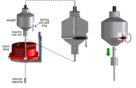
To install a source, the procedure was reversed. The source was lifted up by hand and inserted in the bottom of the weight; the source shaft’s D-shaped cross section ensured alignment with the attachment pin. Once the source was fully inserted, the spring-loaded attachment pin was released to capture the source inside the weight. The pin had two small tines that provided unambiguous visual confirmation of a successful attachment; when the tines disappeared from view inside the weight, the source and weight were securely connected and the plug could be removed.
After the source exchange was complete, the operator reinstalled the door of the housing, reopened the chimney’s upper gate valve, and configured the system so that purified nitrogen gas continually flowed up the chimney through the MiniCal housing and out of the glove box, to purge the volumes of any radon. After several hours had passed (typically by the morning of the following day), the operator ended the nitrogen gas purge, sealed the MiniCal housing off from the glove box by closing the purge valves, opened the chimney’s lowermost gate valve to permit access to the detector, and proceeded with the source deployment.
3.2 Calibration deployments
Deployments were generally conducted “remotely” from the experiment’s nearby control room, where the operator established a virtual network computing (VNC) connection to the MiniCal computer to manipulate the system using the GUI and to monitor the live camera feed.
Before starting a deployment, the operator had to calibrate the system by zeroing the source at a known position. This was accomplished by moving the weight to the position where a notch on its neck was visually aligned with a horizontal reference line in the center of the camera backdrop, a water-jetted sheet of Teflon attached to an electropolished titanium backing plate for contrast (Fig. 7).
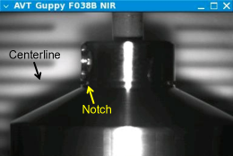
The operator then pressed the “Tare” button in the GUI and the software calculated the source’s center of activity, using the premeasured source lengths and the known location of the reference line with respect to the detector.
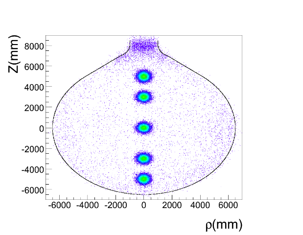
After its position had been established by a tare operation, the source was typically lowered to each desired position in succession, beginning with the uppermost position. When moving between positions, the operator watched the cable as it passed through the camera’s field of view, in order to verify that the system was behaving correctly and to monitor the cable’s condition (e.g., check for frayed wires). After the source came to a stop at a deployment position, the operator turned off the infrared lights, set the driveshaft brake for security, and commenced taking data. A separate data file was recorded for each calibration point (Figure 8).
To enable consistency checks of the system’s position, two small sleeves (“beads”) were swaged onto the cable at the time of its manufacture, and the exact positions of the beads were found by hanging the cable under its expected load in a controlled environment at LBNL and measuring it with a precision tape measure. By comparing the known bead positions with the positions reported by the MiniCal system, the operator could verify the system was accurately reporting the cable payout; this was the only precise means of verifying the system’s performance in situ. The beads had a negligible effect on the system’s measurement of cable payout.
Coarse assessments of the source’s position and the detector’s contamination levels were provided in near real time by an automated online data analysis which processed most of the incoming detector data and displayed the results. The online software was configured for general-purpose analysis and the information it provided was useful primarily for monitoring for any gross abnormalities while a deployment was in progress.
Routine detector calibrations were typically performed once every two weeks. A complete source deployment lasted between 5–8 hours, depending upon the type and intensity of the source and the number of deployment positions. For example, a standard calibration using a 200 Bq 60Co source consisted of placing it at 0.5-meter intervals between m and m (where m is the center of the LS balloon) and leaving it at each point for 15 minutes.
4 Performance
MiniCal was operated routinely from February 2009 until June 2011, when it was dismounted to permit a final deployment of the full-volume calibration system. During its operational period MiniCal performed 65 source deployments and (including tests) executed more than 90 round trips into the detector. Immediately before being uninstalled, MiniCal was used to continuously deploy a CdWO4 crystal assembly to the center of the detector for a special study lasting several days.
4.1 Positioning accuracy and reproducibility
Upon being installed in the KamLAND glove box, MiniCal exhibited near-perfect reproducibility in positioning. However, the cable payout ratio that had been established during system testing no longer appeared to be correct, as the position of the single bead reported by the system disagreed by 2.9 cm with prior tape measurements of the loaded hanging cable—that is, MiniCal reported the cable to be almost 3 cm shorter than we believed was the case. After accounting for the effects on cable stretch from buoyancy ( cm) and the precise value of the attached weight ( cm) there was still a persistent 2.1-cm discrepancy. It thus appeared the system’s payout ratio had somehow been altered in the course of being disassembled, cleaned, reassembled, and installed in the glove box. We made the decision to recalibrate the payout ratio to the premeasured position of the bead; this entailed increasing the payout ratio from 11.298 cm/rev to 11.315 cm/rev, which corresponds to an increase of 0.0027 cm in the effective radius of the z-axis pulley.
In January 2011 the original single-beaded cable was replaced in situ with a similar cable possessing two evenly spaced beads which provided an additional reference point over a longer length. The positions of the two beads had been measured with care beforehand using a precision tape on the hanging cable under load. The new, double-beaded cable verified the correctness of the recalibrated cable payout ratio established roughly two years earlier. The reason for the change in the payout ratio between the system’s offsite testing and onsite operation remains unknown.
A small hysteresis of 2–3 mm of undershoot was consistently observed when the weight returned to its tare position after being deployed to its maximum depth in the detector. This was likely due to a small degree of cable slippage on the z-axis pulley from the lubricating effects of the LS during reel-in. The effect was small, but to minimize the risk of positioning errors we typically placed a source at progressively lower positions during a calibration and only raised it at the conclusion of the deployment.
It was observed that small white crystals sometimes formed on the portion of the cable near the weight when the system was idled for weeks or more. We believe the crystals were PPO from the LS brought up by the system, and their formation was likely promoted by the drying effects of the constant nitrogen gas flux through the MiniCal housing. We observed that the crystals dissolved immediately upon submersion in the LS and did not affect the cable payout accuracy.
4.2 Contamination assessment
The KamLAND detector itself provides the most sensitive means of measuring radioactivity inside it. The level of 222Rn is of particular interest because it was known to have been introduced into the detector by previous calibration systems, and its long-lived daughter 210Pb would have presented a problematic background to detecting 7Be solar neutrinos during the high-purity phase of the experiment.
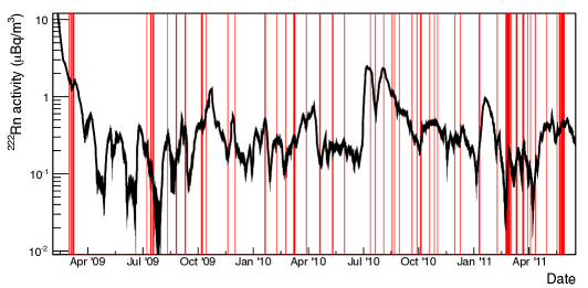
The level of 222Rn activity inside the LS can be determined via its daughters 214Bi and 214Po, whose successive decays occur close together in time ( 1 ms) and therefore generate a robust delayed-coincidence signal. The measured 222Rn activity level vs. time is plotted in Fig. 9 for the period when MiniCal was in use. As the figure shows, there is no apparent correlation between MiniCal deployments and changes in 222Rn activity. Indeed, most of the features in the 222Rn activity history can be attributed to fluctuations in detector operating conditions, usually changes in temperature that generated convection currents which circulated contaminants from the balloon surface into the fiducial volume. It is worth noting that in Fig. 9 we present the radon activity inside a 5.5-m-radius spherical volume primarily for purpose of comparison with data from the previous calibration system [11], but we find the fundamental result is the same if we consider instead a smaller-radius (1.2 m) cylindrical volume centered on the path the MiniCal cable traveled along the detector’s z-axis.
In short, we performed a variety of data-analysis studies and found no indication that MiniCal introduced any contamination, radon or otherwise—even during extended multi-day deployments—above the background levels existing in the LS following purification [15].
5 Conclusions
We successfully designed, built, and operated an ultra-clean calibration system that enabled accurate, precise positioning of radioactive sources along the z-axis of the KamLAND detector. The main device is simple in concept, but its realization was challenging due to the need to make it compact and precise in its operations while also ensuring it would not contaminate or degrade the detector’s highly radiopure liquid scintillator. The system was routinely used to deploy sources inside the detector over a period of more than two years, and no adverse effects on the liquid scintillator were observed. We are now in the process of modifying the system for use in KamLAND-Zen, an experiment utilizing the KamLAND detector to search for neutrinoless double-beta decay of 136Xe [16, 17, 18].
Acknowledgments
We are grateful to the UC Berkeley Physics and LBNL machine shops for manufacturing and assembling many MiniCal components. Thanks are also due to K. Terao and C. Shimmin for their assistance in testing MiniCal; Al Smith of the LBNL Low Background Facility for radioassaying materials; J. Busenitz at the University of Alabama for help in ensuring that new and existing radioactive sources were mechanically compatible with MiniCal; and the former members of the full-volume calibration system team for sharing their experience and advice.
The KamLAND experiment is supported by the Grant-in-Aid for Specially Promoted Research under Grants 16002002 and 21000001 from the Japanese Ministry of Education, Culture, Sports, Science and Technology; the World Premier International Research Center Initiative (WPI Initiative), MEXT, Japan; Stichting voor Fundamenteel Onderzoek der Materie (FOM) in the Netherlands; and the US Department of Energy (DOE) under Grants DE-AC02-05CH11231 and DE-FG03-00ER41138, as well as other DOE grants to individual institutions. The Kamioka Mining and Smelting Company provided service for activities in the mine.
References
- [1] S. Abe, et al., Production of Radioactive Isotopes through Cosmic Muon Spallation in KamLAND, Phys. Rev. C 81 (2010) 025807. arXiv:0907.0066, doi:10.1103/PhysRevC.81.025807.
- [2] K. Eguchi, et al., First results from KamLAND: Evidence for reactor anti-neutrino disappearance, Phys. Rev. Lett. 90 (2003) 021802. arXiv:hep-ex/0212021, doi:10.1103/PhysRevLett.90.021802.
- [3] T. Araki, et al., Measurement of neutrino oscillation with KamLAND: Evidence of spectral distortion, Phys. Rev. Lett. 94 (2005) 081801. arXiv:hep-ex/0406035, doi:10.1103/PhysRevLett.94.081801.
- [4] S. Abe, et al., Precision Measurement of Neutrino Oscillation Parameters with KamLAND, Phys. Rev. Lett. 100 (2008) 221803. arXiv:0801.4589, doi:10.1103/PhysRevLett.100.221803.
- [5] A. Gando, et al., Constraints on from A Three-Flavor Oscillation Analysis of Reactor Antineutrinos at KamLAND, Phys. Rev. D 83 (2011) 052002. arXiv:1009.4771, doi:10.1103/PhysRevD.83.052002.
- [6] T. Araki, et al., Experimental investigation of geologically produced antineutrinos with KamLAND, Nature 436 (2005) 499–503. doi:10.1038/nature03980.
- [7] A. Gando, et al., Partial radiogenic heat model for Earth revealed by geoneutrino measurements, Nature Geoscience 4 (2011) 647–651. doi:10.1038/ngeo1205.
- [8] G. Keefer, et al., Laboratory studies on the removal of radon-born lead from KamLAND’s organic liquid scintillator, Nucl. Instrum. Meth. A 769 (2015) 79–87. arXiv:1312.0977, doi:10.1016/j.nima.2014.09.050.
- [9] G. Keefer, First Observation of 7Be Solar Neutrinos with KamLAND, Ph.D. thesis, University of Alabama, Tuscaloosa, Alabama (2009).
- [10] A. Gando, et al., 7Be Solar Neutrino Measurement with KamLAND, Phys. Rev. C (2014) submitted for publication. arXiv:1405.6190.
- [11] B. E. Berger, et al., The KamLAND Full-Volume Calibration System, JINST 4 (2009) P04017. arXiv:0903.0441, doi:10.1088/1748-0221/4/04/P04017.
- [12] S. J. Freedman, G. T. Garvey, M. Kroupa, J. Napolitano, J. Worthington, A Liquid Scintillator Cosmic Ray Active Shield, Nucl. Instrum. Meth. 215 (1983) 71–77. doi:10.1016/0167-5087(83)91292-9.
- [13] Ultra High Vacuum Component and Assembly Production Requirements, LBNL Engineering Specification No. 10156A.
- [14] https://sites.google.com/a/lbl.gov/low-background-facility.
- [15] Y. Takemoto, Observation of 7Be Solar Neutrinos with KamLAND, Ph.D. thesis, Tohoku University (2014).
- [16] A. Gando, et al., Measurement of the double- decay half-life of 136Xe with the KamLAND-Zen experiment, Phys. Rev. C 85 (2012) 045504. arXiv:1201.4664, doi:10.1103/PhysRevC.85.045504.
- [17] A. Gando, et al., Limits on Majoron-emitting double-beta decays of Xe-136 in the KamLAND-Zen experiment, Phys. Rev. C 86 (2012) 021601. arXiv:1205.6372, doi:10.1103/PhysRevC.86.021601.
- [18] A. Gando, et al., Limit on Neutrinoless Decay of Xe-136 from the First Phase of KamLAND-Zen and Comparison with the Positive Claim in Ge-76, Phys. Rev. Lett. 110 (6) (2013) 062502. arXiv:1211.3863, doi:10.1103/PhysRevLett.110.062502.