A hadronic calorimeter with Glass RPC as sensitive medium.
Abstract
The SDHCAL technological prototype is a m3 high-granularity Semi-Digital Hadronic CALorimeter using Glass Resistive Plate Chambers as sensitive medium. It is one of the two HCAL options considered by the ILD Collaboration to be proposed for the detector of the future International Linear Collider project. The prototype is made of up to 50 GRPC detectors of 1 m2 size and 3 mm thickness each with an embedded semi-digital electronics readout that is autotriggering and power-pulsed. The GRPC readout is finely segmented into pads of 1 cm2. Measured performances of the GRPC and the full SDHCAL prototype in terms of homogeneity, low noise and energy resolution are presented in this proceeding.
keywords:
GRPC; Calorimetry; Embedded electronics1 Introduction
This article describes a hadronic calorimeter prototype. The Semi-Digital Hadronic CALorimeter (SDHCAL) is one of the two hadronic calorimeter options considered by the ILD (International Large Detector) Collaboration [1] to be proposed for the detector of the future International Linear Collider (ILC). ILC detectors are designed for Particle Flow Algorithms (PFA) [2]. For optimal use of PFA, calorimeters needs to be homogeneous and finely segmented.
2 SDHCAL concept
The SDHCAL prototype meets the ILC requirements by the combination of various technological choices. The homogeneity is achieved by the use of large Glass Resisitive Plate Chambers (GRPC) as the active medium combined with a power-pulsed embedded electronics. The power-pulsing suppresses the need of integrating a cooling circuit inside the detector by reducing the power consumption and heating. The homogeneity is further achieved by having all services (gas inflows and outflows, high voltage, data readout, etc.) to be on only one side of the GRPC and outside the HCAL.
The fine segmentation is achieved transversally by the readout electronics system. An embedded Printed Circuit Board (PCB) with a checked side made of 1 cm2 copper pads, reads the signal created by the passage of charged particles in the GRPC detector. The other side of the PCB holds the HARDROC ASICs [3], that collect signals from the copper pads, digitizes them and transmits them to the outside data acquisition system. The ASIC provides 2-bit readout.
The typical size of an avalanche inside the GRPC is around 1 mm2. At high energy, the shower core is very dense, up to more than 100 avalanches per cm2, and simple binary readout will suffer from saturation effect. Semi-digital readout (2-bit) reduces this effect and improves the energy reconstruction.
The choice of this semi-digital scheme rather than the binary one was motivated by simulation studies [4] and the three corresponding thresholds are used to tag pads fired by few, little or many crossing particles inside the shower. This choice has been validated by results [5] that will be discussed later in this article.
3 The GRPC cassette

A GRPC cassette [4] has a 1 m1 m area and is 11 mm thick (see figure 1). It contains one GRPC and its associated electronics. The cassette is a thin box consisting of two 2.5 mm thick stainless steel plates separated by 6 mm wide stainless steel spacers which form the walls of the box. One of the two plates is 20 cm larger than the other to hold the PCBs used for the data acquisition as well as the gas outlets and the high voltage box. Precision machined stainless steel spacers, insulated from the GRPC, are making the cassette’s sides. A polycarbonate mask is added around the ASICs to ensure that once the cassette is closed, the PCB is forced to stay into contact with the GRPC anode. This cassette structure ensures a homogeneous efficiency of the GRPC signal collection by the PCB copper pads.
The cassettes are inserted into a self-supporting structure [4] with 50 13 mm thick spaces separated by 1.5 cm thick stainless steel plates. The SDHCAL prototype is then a sampling calorimeter with 2 cm thick absorber layers, nearly one radiation length, and 6 mm thick active detectors.
3.1 GRPC
The GRPC is used in saturated avalanche mode [6]: the avalanche is initiated by the crossing of the 1.2 mm thick gas gap by one or more charged particles. The gap is framed by two electrodes made of borosilicate float glass [7]. The anode and cathode thickness are 0.7 mm and 1.1 mm respectively. The smaller anode thickness enhances the signal in the copper pad closest to the crossing particle and lowers the relative signal seen by neighbouring pads. The high voltage used is typically 7 kV. A glass fiber frame, width 3 mm, height 1.2 mm is used to seal the gas volume.
The gas distribution within the chamber is done through an L-shaped channel delimited by the chamber frame and a series of PMMA fibers [7]. Gaps between the fibers allow the gas to leave the channel at regular intervals, expanding into the main chamber volume. Under usual operating conditions the chamber volume is exchanged every 20 minutes. This needs a gas flow of 3.6 l/h and an overpressure of 1 mbar in the chamber. This overpressure corresponds to a force per unit area of 100 N/m2, which almost balances the attractive electric force between the plates. The operating gas is a mixture of 93% of TFE, 5% of C02 and 2% of SF6. TFE has been chosen for its low ionisation energy enabling efficient creation of avalanches. CO2 and SF6 are used as UV and electron quenchers respectively. Studies of gas mixture performances are described in [8].
To maintain the gas gap over the entire chamber area, ceramic balls with 1.2 mm in diameter are glued to the cathode every 10 cm. A finite element analysis [7] taking into account the electric force and the glass plates weight has determined that for this distribution of balls, the maximum deflection of the anode glass is 44 m. When the gas circulates, this deflection is reduced. To ensure the physical integrity of the chamber in case the gas circulates but the high voltage is switched off, 13 ceramic balls are replaced for each m2 by cylindrical glass disks glued on both electrodes [8]. The glass electrodes are coated with a cheap bi-component painting based on colloidal graphite. This painting can be silkscreen printed for a very good coating uniformity. In addition, the resistivity is adjustable by varying the proportion of the two components. The coating provides uniform spread of the high voltage over the 1 m2 electrodes.
3.2 Electronics
A 1 m2 GRPC is tiled with 6 PCB size of m2. The PCBs have eight layers. On one external face, 1536 copper pads of cm2 are printed. Copper pads are separated by 406 m. On the opposite face, 24 HARDROC2 ASICs [3] are soldered. Each ASIC is connected to pads through the PCB. The electronic channel cross-talk between two adjacent pads is less than 2% [9].
Each of the 64 channels of an ASIC is made of a fast low-input- impedance current-preamplifier. The gain of each preamplifier can be varied over 6 bits to correct for the non-uniformity between channels. The 2-bit readout is done by 3 variable fast shapers (15-25 ns), each one followed by a low-offset discriminator. Each fast shaper covers a different dynamic range leading to a total channel dynamic range from 10 fC to 15 pC.
When the ASIC is in acquisition mode, the 192 discriminator outputs are checked each 200 ns. If one is fired, an event is stored in an integrated digital memory. This auto-triggering mechanism enables the operation of the calorimeter without external triggers. An ASIC event consists of the ASIC identification number, a 3-byte clock counter and the output state of the 192 discriminators. The HARDROC2 can store up to 127 ASIC events. Once the memory is full, the ASIC raises a signal and waits for instruction from the external Data Acquisition (DAQ) system.
The ASICs are daisy chained on the PCB. Configuration data (the 64 preamplifier gain, the 192 discriminator thresholds, etc.) and the readout data are transfered through the chain of ASICs. The m2 PCBs can be chained themselves. On a 1 m2 GRPC, the 6 PCBs are paired and connected to 3 DAQ interface boards (DIF) located on the larger cassette plate. This daisy-chaining reduces the amount of cables needed between the cassette and the external DAQ
An important feature of the ASIC is the possibility to be power-pulsed. It is possible to switch on/off the power-hungry parts of the ASICs by sending external control signal. The portion of the ASICs that should be power-pulsed is configurable before the acquisition starts. With everything on, the power consumption is 1.425 mW per copper pads. When most of the ASICs is switched off, it reduces to less than 0.2 muW. The ILC operating cycle [10], will have a 200 ms period in which collisions occur only during 0.95 ms. By switching on the HARDROC2 only 0.5% of the time, the SDHCAL power consumption is below 10 W per channel and sufficiently low to avoid the need of an internal cooling system.
4 Prototype assembly
4.1 The DAQ
DAQ is driven by the XDAQ software [11]. The ASICs configuration data are stored in an ORACLE database and sent to the DIFs via HDMI cables. Clock synchronisation is sent through the same HDMI cables. The readout data are retrieved from the DIFs through USB cables. The use of USB concentrators and specific boards (DCC) to dispatch the HDMI signals allows to scale the DAQ from 1 cassette to the full prototype which comprises more than 460000 readout channels.
4.2 Single cassette uniformity
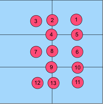
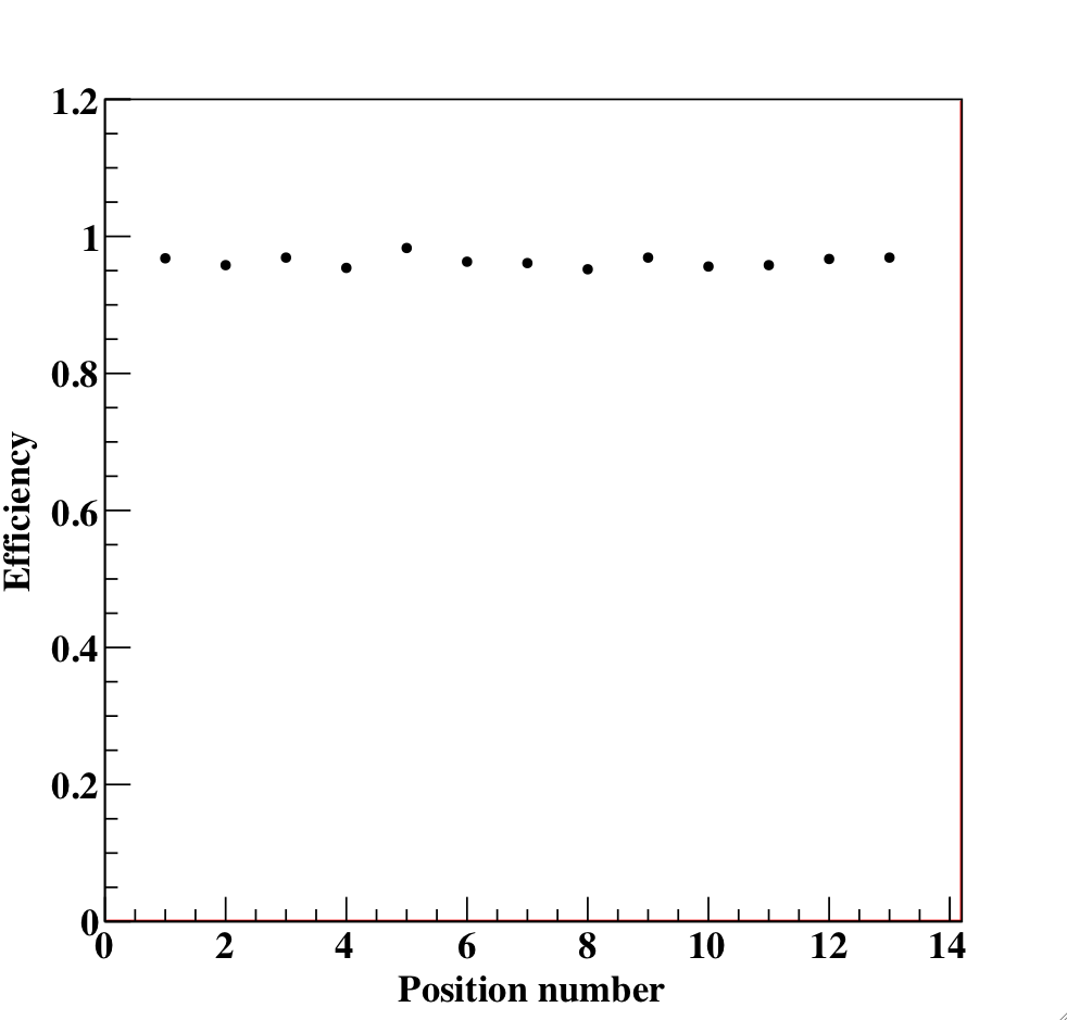
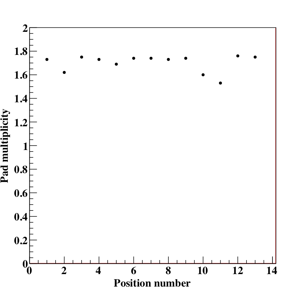
A single GRPC cassette was tested in a test beam. The beam was sent at various locations of the 1 m2 cassette: at the center of different m2 PCBs and at the junction of 2 or 4 PCBs. The 13 locations where the beam was shot are shown in figure 2. The response of the chamber was checked for each of the 13 locations. The response consists of the efficiency and the multiplicity. The efficiency is the fraction of crossing charged particles that fires at least one channel at a distance of less than 3 cm around the expected position of the crossing charged particle. The multiplicity is defined as the mean number of fired channels when a crossing particle fires the chamber. Figure 2 shows a very uniform response of the tested chamber.


4.3 Prototype construction
For the construction, 10500 ASICs were tested and calibrated using a dedicated robot that was used by CMS (yield : 93% ). 310 PCBs were produced, cabled and tested. They were assembled into sets of six to make 1 m2 ASUs. 170 DIFs and 20 DCCs were built and tested. 50 detectors were built and assembled with their electronics embedded into cassettes. Cassettes were tested by sets of 6 using a cosmic test bench. The mechanical structure was built separately. Full assembly of the structure, the cassettes and the HV and cooling services took place at CERN.
4.4 Prototype operation
The full prototype has then been exposed to pion and electron beams at the CERN SPS for 3 periods totalling 5 weeks. For these beam tests, 48 GRPCs were inserted inside of the absorber structure. The 3 thresholds for the 2-bit readout were set to 114 fC, 5 pC and 15 pC respectively, the average MIP induced charge being around 1.2 pC. The same electronics gain was used for all the channels and the high voltage applied on the GRPC was of 6.9 kV. The proportion of dead channels was about 1 per mil.
5 Data analysis
5.1 Time analysis
In the trigger-less data acquisition mode used for the test beam, all the activity in the detector is recorded: isolated hits (fired pads) due to noise, particles crossing the detector or showering in it. The electronics runs with a clock tick of 200 ns. For the vast majority of clock ticks, there are no hits recorded in the prototype. Analysis of the random hit distribution leads to a mean noise estimation of 0.35 hits per 200 ns for the more than 460000 readout channels [5]. Potential physics events are reconstructed by combining hits from 3 consecutive clock ticks if the middle clock tick has at least 7 hits.
5.2 Data quality
To monitor the calorimeter performance, the efficiency and multiplicity of the GRPC response are estimated using beam of muons. For each layer, muon tracks are reconstructed from the hits of the other layers. The expected impact point of the track in the layer under study is then used to compute efficiency and multiplicity for the chamber as described in section 4.2. The procedure can be done to monitor a full chamber or any portion of it down to pad by pad monitoring. For the test beams, the number of recorded beam muon events was sufficient to monitor the calorimeter at the ASIC level (a group of 8 by 8 pads). The efficiency has been measured to be 95% with a 6% dispersion between ASICs. The multiplicity has been measured to be 1.73 hits per crossing particles with a dispersion of 0.25 hits between ASICs.
5.3 Efficiency modeling
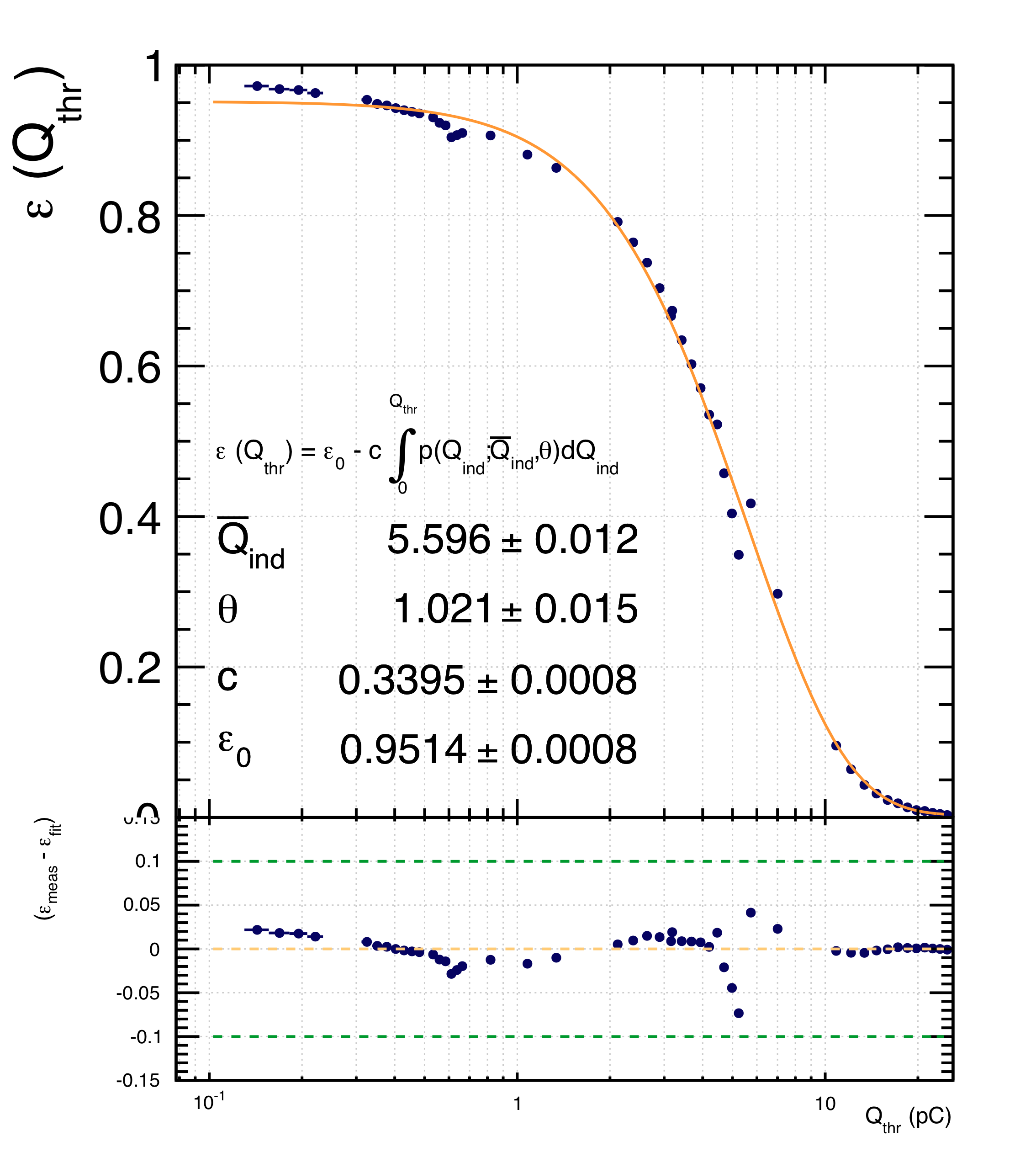
During special runs, the thresholds were varied in a few layers to measure the efficiency as a function of the threshold as shown in figure 3 left. The charge induced by an avalanche can be modelled by a Polya distribution (eq. 2). The efficiency is modelled as the combination of the probability for a crossing charged particle to initiate an avalanche and the probability that the induced charge is above the threshold. This leads to the modelling of equation 1 with the values of the model parameters shown on figure 3 left.
| (1) | |||||
| (2) |


5.4 Pion energy reconstruction
A simple selection of showers due to interacting pions is done for energy reconstruction: electrons are rejected by requiring that the shower starts after the fifth layer or that more than 30 layers have at least 4 hits. Muons are rejected by asking that the mean number of hits per fired layers should be above 2.2 and that at least 20% of the fired layers have a spatial hit distribution with a RMS above 5 cm. Neutral particles are rejected by requiring the presence of at least 4 hits in the first 5 layers. Details of the selection are described in [12]
The energy of a pion is reconstructed as
| (3) |
where and , and are the exclusive number of hits associated to the first, second and third threshold, and, , and are quadratic functions. The reconstructed energy as a function of the beam energy is shown on figure 3 right. The calorimeter response is linear with deviations from linearity below 5% for pion energies between 7 GeV and 80 GeV. The corresponding resolution decreases from 25% for 5 GeV pions down to 8.9% for 80 GeV pions [12]. Further improvements on the energy resolution are shown in [13].
6 Outlook
A prototype of a semi-digital imaging calorimeter has been build using GRPC as sensitive detectors. The GRPC detectors have proven to be cheap, homogeneous, thin, with very low noise and very few dead zones. The GRPCs are associated with an embedded readout electronics and allow a very fine segmentation of the readout of 9216 channels per m2. Further developments are ongoing on the software reconstruction. For example, the use of Hough Transform to improve tracking and energy reconstruction [14]. Hardware developments are ongoing as well to increase the size of the chamber to 2 m2 which implies to revisit the gas distribution inside the chamber and the ASICs daisy chaining.
Acknowledgements.
This work has been done within the SDHCAL group of the CALICE collaboration. The SDCHAL group comprises teams from IPNL (Lyon, France), LLR (Palaiseau, France), LAPP (Annecy, France), LPC (Clermont-Ferrand, France), OMEGA (Orsay, France), CIEMAT (Madrid, Spain), UCL (Louvain, Belgium), Universiteit Gent (Belgium), Tsinghua University (Beijing, China), Université de Tunis (Tunisia).References
- [1] Ties Behnke, et al., The International Linear Collider Technical Design Report - Volume 4: Detectors., 2013.
- [2] J.C. Brient., Improving the jet reconstruction with the particle flow method: An introduction., in proceedings of XI International Conference on Calorimetry in Particle Physics Calor 2004, March 29 – April 2, 2004, Perugia, Italy [\physics0412149]
- [3] C. de La Taille. Performance of 2nd generation CALICE/EUDET ASICs. in proceedings of XIV International Conference on Calorimetry in Particle Physics Calor 2010, May, 10 – 14, 2010, IHEP, Beijing, China, J.Phys.Conf.Ser. 293:012016, 2011.
- [4] I. Laktineh. Construction of a technological semi-digital hadronic calorimeter using GRPC. in proceedings of XIV International Conference on Calorimetry in Particle Physics Calor 2010, May, 10 – 14, 2010, IHEP, Beijing, China, J.Phys.Conf.Ser. 293:012077, 2011.
- [5] CALICE collaboration, First results of the CALICE SDHCAL Technological Prototype, \hrefhttps://twiki.cern.ch/twiki/pub/CALICE/CaliceAnalysisNotes/CAN-037.pdf CALICE Analysis Note 37.
- [6] V. Ammosov, et al., Study of RPCs with 1x1 cm2 Read-Out Pads Operated in the Saturated Avalanche Mode., \hrefhttp://web.ihep.su/library/pubs//prep2007/07-22-e.htmIHEP 2007-022.
- [7] M. Bedjidian, et al., Glass resistive plate chambers for a semi-digital HCAL., Nucl.Instrum.Meth.,A623:120-122, 2010.
- [8] Robert Kieffer. Caractérisation d’un calorimètre hadronique semi-digital pour le futur collisionneur ILC., \hrefhttp://tel.archives-ouvertes.fr/tel-00678578PhD thesis, Université Lyon 1, Lyon, France, 2011.
- [9] M. Bedjidian, et al. Performance of Glass Resistive Plate Chambers for a high granularity semi-digital calorimeter, \jinst62011P02001.
- [10] Chris Adolphsen, et al.,The International Linear Collider Technical Design Report - Volume 3.II: Accelerator Baseline Design., 2013.
- [11] V. Brigljevic, et al., Using XDAQ in application scenarios of the CMS experiment. in proceedings of 2003 Conference for Computing in High-Energy and Nuclear Physics (CHEP 03), March, 24–28, 2003, La Jolla, California. [\hepex0305076]
- [12] CALICE collaboration, Addendum to the CAN-037 note on the first results of the SDHCAL technological prototype,\hrefhttps://twiki.cern.ch/twiki/pub/CALICE/CaliceAnalysisNotes/CAN-037a.pdf CALICE Analysis Note 37 Addendum a.
- [13] CALICE collaboration, Addendum-2 to the CAN-037 note on the first results of the SDHCAL technological prototype,\hrefhttps://twiki.cern.ch/twiki/pub/CALICE/CaliceAnalysisNotes/CAN-037b.pdf CALICE Analysis Note 37 Addendum b.
- [14] A. Petrukhin, Energy measurement with the SDHCAL prototype in proceedings of Technology and Instrumentation in Particle Physics 2014, June, 2 – 6, 2014, Amsterdam, the Netherlands \posPoS(TIPP2014)031.