Generation of vacuum ultraviolet radiation by intracavity high-harmonic generation toward state detection of single trapped ions
Abstract
VUV radiation around 159 nm is obtained toward direct excitation of a single trapped 115In+ ion. An efficient fluoride-based VUV output-coupler is employed for intracavity high-harmonic generation of a Ti:S oscillator. Using this coupler, where we measured its reflectance to be about 90 , an average power reaching W is coupled out from a modest fundamental power of 650 mW. When a single comb component out of teeth is resonant to the atomic transition, hundreds of fluorescence photons per second will be detectable under a realistic condition.
I Introduction
Optical clocks based on trapped single ions and neutral atoms in optical lattices have reached frequency uncertainties in the order of Chou10 ; Bloom14 ; Ushijima14 . This level of accuracy brings strong impact to applications in science and technology, such as precise determination of physical constants, tests of fundamental physics theories, network synchronization, geodesy, and redefinition of the second. Many of the optical clocks use atoms and ions with two outer electrons as the optical frequency reference according to the original proposal by Dehmelt Dehmelt82 . The idea of single ion clocks has been extended to optical lattice clocks where multiple neutral atoms are confined in the Lamb-Dicke regime Katori03 . Energy levels of such atomic species (B+, Al+, Ga+, In+, Tl+, Sr, Yb, Hg) is shown in Fig. 1a with In+ as an example. Their weakly allowed – transitions with linewidth smaller than 1 Hz are used as clock transitions. The clock transitions are observed using the – transitions as follows: Excitation of the – transition after the interrogation of an atom with clock lasers results in a lot of fluorescent photons when the clock laser is off-resonant from the – transition, and results in absence of photons when it is resonant. This method called “electron shelving” is relatively easily implemented to lattice clocks since the – transition lies in visible wavelength. In contrast, application to the ions is intractable, because the – transitions locate in the vacuum ultraviolet (VUV) region as is exemplified in Fig. 1a, where generation of coherent radiation is challenging. The VUV radiation is also expected to laser-cool the ion, and this demands the VUV radiation to be continuous-wave (CW).
The solution to overcome this difficulty has been provided by quantum logic spectroscopy (QLS), in which another ion with a convenient energy level structure is trapped simultaneously and serves as a coolant ion as well as a quantum state probe Schmidt05 . By this way the Al+ clock has been realized without need for VUV radiation to excite the – transition at 167 nm. The smallest inaccuracy of single-ion clocks has been reported with the Al+ clock Chou10 , but the implementation of QLS seems technically demanding since no other demonstrations are so far reported.
Here, we propose an alternative approach for the ion clock, in which VUV radiation is generated via high-harmonic generation (HHG) Brabec00 ; Atto_Sci_07 , and is used only for quantum state detection of single ions. Cooling of the ions is supplied by sympathetic cooling, and therefore, a single-mode CW radiation is not required. Detection of single ions might be suffice with a quasi-CW radiation which is actually a singled-out mode in “VUV combs” generated via intracavity HHG Jones05 ; Gohle05 . Sympathetically cooled ions are relatively easily prepared Hayasaka12 ; Herschbach12 , and an example of such ion arrays including an In+ is shown in Fig. 1b. Besides this main advantage of simpleness, our method has another advantage of scaling to multi-ion systems for improved stability Herschbach12 . Although the current protocol of QLS is limited to systems with one target ion, the state detection using VUV radiation is applicable to systems with multiple target ions. Such a quasi-CW beam in the VUV region might be used as a clock laser that interrogates a thorium nucleus for realizing a more accurate optical clock Peik03 ; Beck07 ; Rellergert10 ; Campbell11 ; HS13 . Several methods which might be applicable to direct excitation of VUV transitions have been developed as follows. Triply-resonant four-wave mixing is implemented to generate 121 nm light Kolbe12 . KBBF crystals are used to demonstrate generation of 156 nm radiation by sum-frequency mixing Kanai04 and generation of 153 nm radiation via frequency conversion Nomura11 . Raman-resonant four-wave mixing in parahydrogen has been proposed more recently to generate 120–200 nm VUV radiation Zheng14 .
In section II we discuss the feasibility of detecting the – fluorescent photons at 159 nm from a single In+ ion excited with a quasi-CW beam obtained via intracavity HHG. Section III describes experiments to generate the VUV radiation as the fifth harmonic of femtosecond (fs) frequency combs peaked at 795 nm. We conclude this work and discuss the future prospects in section IV.
II Single ion detection with a quasi-CW VUV beam
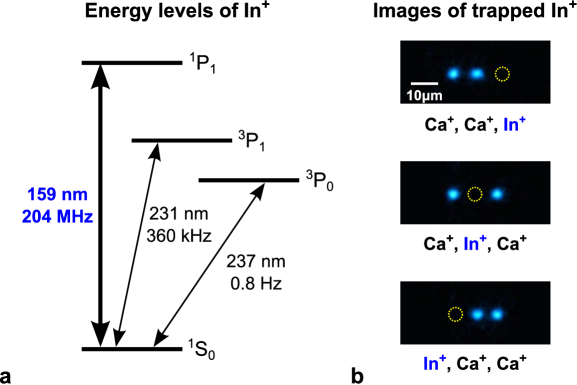
In this section we discuss on the possibility of detecting the quantum state of a single trapped ion by direct excitation using a quasi-CW beam generated as VUV combs. Our target is the 115In+, which is one of the candidates for single-ion optical clocks included in Dehmelt’s original proposal Dehmelt82 . Recent proposals on the In+ optical clocks estimate fractional frequency inaccuracy of 10-18 level owing to its small black body radiation shift Hayasaka12 ; Herschbach12 . Previously, implementation of the In+ clock has been investigated using relatively weak – transition at 230 nm for detection, but its performance was limited to 10-13 level vonZanthier00 ; Wang07 . If the direct excitation of the – transition at 159 nm is possible, roughly 500 times more fluorescent photons are emitted from a single In+, and it makes much faster quantum state detection than that with the – transition. Combined with robust trapping of the ions by sympathetic cooling, the VUV detection scheme will enable an easier implementation of the optical clock. The same method might be applicable not only to a multi-In+ clock, but also to a single Al+ clock as well as to multi-Al+ clock, where the – transition lies at 167 nm.
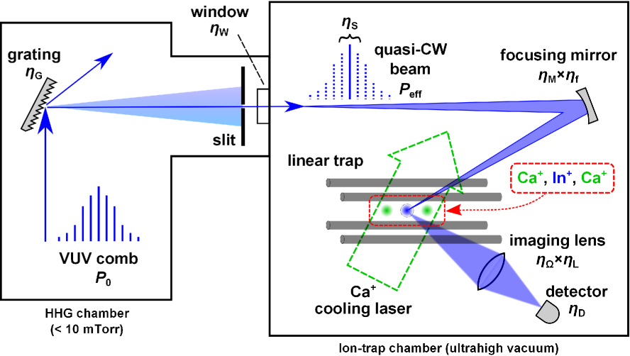
We assume a setup depicted in Fig. 2 for direct excitation of a single In+ with a VUV beam generated from HHG. The whole optical path between the VUV source and the detector is evacuated to avoid absorption by air: The VUV source and the ion trap will be deployed in separate vacuum chambers for their different vacuum levels, and will possibly be connected through a high-transmittance fluoride window. We focus on the case of single ion in this paper, but extension to multiple ions might be possible by upgrading the optics for simultaneous illumination of ions. The VUV comb is incident on a grating, and modes around the – transition are chosen by a slit to avoid detrimental influence by excess modes such as increased background photons due to scattering, and charging of insulating materials due to photoelectric effect. The quasi-CW beam generated in this way is focused onto the In+ sympathetically cooled with two Ca+. Fluorescent photons emitted from the In+ are imaged onto the detector using a single lens. Quantum state detection of the single ions is enabled by sufficient number of fluorescent photons detected with a photomultiplier tube (PMT) or a image-intensified charge-coupled-device (CCD) camera.
In order to assess the feasibility of the VUV detection method, it is crucial to know the total average power [W] of the VUV comb required for detecting [cps] (counts per second) fluorescent photons with the detector. Rough estimation is made on by considering the steps of the direct excitation of single ion consisting of generation of the quasi-CW beam focused to the ion, fluorescent photon scattering by the single ion and collection and detection by the detector. The VUV comb is incident on the grating, and only the mode interacting with the ion is transmitted through the slit, and is focused with a curved mirror onto the ion. After this step, the quasi-CW power which effectively contributes to excitation of the ion, is given by
| (1) |
Here is the total propagation efficiency to the ion, in which , , , and denote, respectively, grating efficiency, window transmittance, power ratio of the target comb-mode relative to the whole spectrum, reflectance of the focusing mirror and focusing efficiency to the spot with a radius of . The ion emits fluorescent photons with a rate of
| (2) |
where is the spontaneous emission rate and is the saturation intensity, respectively, of the – transition. is the spot size. The photons are imaged onto a detector with a quantum efficiency of by a single lens which spans a solid angle covering of the whole solid angle, and has a transmittance of . Then the count rate [cps] is obtained by the detector, where is an overall efficiency in the detection side. Thus the photon counting rate per the average VUV-comb power can be estimated by the following expression:
| (3) |
| description | symbol | estimation |
|---|---|---|
| spontaneous emission rate | 2204 MHz | |
| saturation intensity | 6.67 W/cm2 | |
| spot radius | 0.5 m | |
| grating efficiency | 0.34 | |
| window transmittance | 0.85 | |
| spectrum occupancy | 5.310-6 | |
| mirror reflectance | 0.95 | |
| focusing efficiency | 0.85 | |
| photon collection efficiency | 0.045 | |
| imaging lens transmission | 0.85 | |
| detector quantum efficiency | 0.15 |
Now we proceed with estimation on required for the single ion detection with realistic experimental parameters. The spontaneous emission rate of the – transition is lately revised to be [MHz] NIST_ASD . The saturation intensity of the transition is calculated from , where Js is the Planck constant and is the speed of light. Using the above value of and wavelength = 158.6 nm, the saturation intensity is = 6.67 W/cm2. The advantage of sympathetically cooled ions is that even the invisible ion can be localized within a known region much smaller than micrometer scale. Localization of a Ca+ Doppler-cooled in a conventional linear trap after a routine procedure of micromotion compensation was measured to be as small as 16 nm (full width at half maximum) along the trap axis direction Guthohrlein01 . The wave packet size of the In+ cooled by this Ca+ is estimated times larger due to dependence of the axial secular frequency on mass (), but the localization is still in the order of tens of nanometers. This allows targeting the ion with the smallest spot size possible with focusing optics. Here we consider a simple case in which a collimated Gaussian beam is tightly focused by a concave mirror (denoted as “focusing mirror” in Fig. 2). When we take a mirror diameter mm and a radius of curvature mm as an example, the effective diameter of the focused Gaussian spot is estimated to be m. Thus we assume that the VUV radiation is focusable to the spot radius e.g. = 0.5 m, which is more than three times larger than . We also estimated the focusing efficiency = 0.85, which denotes the reduction of intensity from the ideal focusing. Later we discuss on derivation of in some detail. Grating efficiency of = 0.34 was realized at 160 nm Caruso81 . We estimated that the intensity ratio of the target comb-mode to the whole spectrum, namely spectrum occupancy, is = 5.3, which is an important issue and is discussed in detail later. Mirror reflectance is estimated to be 95 , because such a high-reflection coating is available at the wavelengths longer than 150 nm VUV_spec_book . For collection of fluorescent photons, we assume a use of a lens with a focal length of = 30 mm in 25 mm diameter made of MgF2. This gives photon collection efficiency of = 0.045. A typical transmittance of was realized with a 3-mm-thick MgF2 VUV_spec_book , and thus we use a lens transmission efficiency of . Note this value is also used for the window transmittance . The quantum efficiency of our image intensified CCD camera (PI-MAX 3, Princeton Instruments) is 0.15 at 159 nm, which is similar to the maximum efficiency of PMTs. Therefore we take this value as the detector efficiency .
Next we estimate the focusing efficiency in detail. We take into account of aberration caused by the focusing mirror which reflects the VUV radiation originally generated as a Gaussian beam, because the accuracy of mirror surface is closely related to the beam focusing efficiency. Surface accuracy is usually measured at 633 nm (typically using a helium-neon laser), and ( nm) can be easily achievable for the mirror diameter mm. The accuracy of 63.3 nm corresponds to phase aberration of rad at 159 nm. Then one can evaluate the Strehl ratio of a Gaussian beam, , which represents the ratio of the central irradiance of point-spread function before and after being affected by aberrations Mahajan05 . is the variance of the phase aberration in a Gaussian beam. Due to the fact that surface roughness of a polished mirror is usually below a few angstroms, and that spatial frequency of surface irregularity is not high, we consider monochromatic primary aberrations, e.g. spherical aberration (), coma (), and astigmatism () Mahajan05 . In each case, the Strehl ratio of around can be maintained. In other words, roughly power in the reflected VUV beam is not blurred and will be correctly focused even with aberration which may be caused by the practical surface accuracy. Note, further improvements of the Strehl ratio is possible by combining and balancing several aberrations Mahajan05 . In contrast to the focusing mirror described above, the beam quality would not be affected as much by a surface irregularity of a dichroic beam splitter which should be placed in advance of the beam input in Fig. 2 and separates fundamental and high-harmonic beams. As shown later in this paper, the beam diameter at the splitter is normally as small as 1 mm. The corresponding primary aberrations caused by that small area is much smaller than that in the case of the concave focusing mirror ( mm) because spherical aberration, coma, and astigmatism vary with the fourth, third, and second power, respectively, of radial distance from the beam axis. Thus the Strehl ratio for the splitter is estimated to be near unity. Note that surface accuracy of is commercially available in substrates with the thickness and the diameter of 1 mm and 5 mm, respectively.
Finally we estimate the spectrum occupancy as follows. Nonlinear optical processes in the HHG can be categorized as perturbative, intermediate, and strong-field regimes according to the strength of fundamental electric field interacting with atoms Brabec00 . As we show in section III.2, the peak intensity of fundamental fs pulses in our setup is estimated to be around W/cm2, which is presumably within the perturbative regime. In fact, we calculated the scale parameters in the ref. Brabec00 as follows, and . Here, C, V/cm, and m, denote, respectively, the elementary charge, electric field strength, and the Bohr radius of Xe atoms used as nonlinear media for HHG. We also used kg, V/A, and eV, representing the electron rest mass, the impedance of vacuum, and the ionization potential of the Xe atoms NIST_ASD , respectively. is the reduced Planck constant and eV is a photon energy at 795 nm. fs/rad is a response time of induced atomic dipole moment. Thus we confirmed that the following condition is fulfilled as and , that is the definition of the perturbative regime Brabec00 . This may allow us to describe electric field for the th harmonic as , where denotes the electric field at fundamental wavelength. If we assume a transform-limited pulse e.g. with a Gaussian temporal envelope whose width is characterized by , simple Fourier transform analysis reveals that the spectral width for the th harmonic in the frequency domain becomes times broader than that for the fundamental: As we show in section III.2, a spectral bandwidth of the fundamental fs pulses is THz (20 nm centered at 795 nm). This may yield THz ( nm) for the fifth harmonic. is obtained as an inverse of the number of VUV-comb teeth (). Here we introduced an experimental repetition rate of our fs frequency comb as MHz.
In summary, the photon counting rate per the average VUV-comb power, , is estimated to be roughly 87 cps/W, using the above parameters summarized in table 1. According to the previous report in which single In+ is detected using the – transition at 230 nm Wang07 , the quantum state detection was demonstrated with a photon counting rate of 500 cps. This rate is obtained with W in our scheme. In the following section III, we experimentally confirmed that this level of power can be generated using our existing setup.
III Intracavity high-harmonic generation using VUV-OC
High-harmonic generation (HHG) has been intensively studied for generation of radiation whose wavelengths are shorter than 190 nm VUV region, in order to realize attosecond pulses enabling one to probe and control electron dynamics in the time domain Atto_Sci_07 . The Ti-sapphire (Ti:S) based system is convenient for a tool of spectroscopy because it can generate various wavelength. The HHG process, however, requires very strong laser intensities ( W/cm2). Though chirped pulse amplification of Ti:S oscillator has been widely used to realize such a condition, its repetition rate cannot easily exceed 20 kHz Brabec00 . Alternatively, intracavity HHG using fs frequency combs has also realized such a strong intensity by using a passive fs enhancement cavity (fsEC), while it can maintain a repetition rate of 100-MHz-level. The intracavity HHG thus realized frequency combs in the VUV and extreme ultraviolet (XUV) region Jones05 ; Gohle05 . More recently, direct frequency-comb spectroscopy using such VUV or XUV combs have been implemented for probing transition frequencies in argon at 82 nm and in neon at 63 nm Cingoz12 , or in xenon at 147 nm Ozawa13 . The XUV combs may also be useful for testing bound-state quantum electrodynamics in a single helium ion Herrmann09 .
Considering to apply the direct state detection scheme to an In+ clock being developed in our institute Hayasaka12 , we built a setup of an intracavity HHG and reported VUV-comb generation centered at 159 nm Wakui11 . But further power-scaling is needed in order to realize such a VUV detection of single trapped ions. One of the straightforward ways to scale up the harmonic yield would be just to enlarge fundamental power of the fs frequency combs Paul08 ; Ruehl10 for HHG. The outcoupling method of high harmonics from the fsEC is also the key to scale up their yield. Several methods were previously demonstrated using e.g. a bulk sapphire window as a Brewster plate Jones05 ; Gohle05 , a diffraction grating ruled onto a fsEC mirror surface Yost08 , a diffraction nanograting Yang11 , an anti-reflection-coated grazing incidence plate Pronin11 , a VIS/IR-XUV beamsplitter Pupeza11 , a Brewster plate made of MgO substrate with a dielectric coating for VUV Ozawa13 , and a pierced fsEC mirror Pupeza13 .
In this section, we report a novel efficient VUV output coupler (VUV-OC) for the fifth harmonic of Ti:S oscillator. The VUV-OC consisting of a thin SiO2 substrate and fluoride-multilayer coating, works as a Brewster plate which can be inserted in the fsEC driven at a fundamental near-infrared (NIR) wavelength, and at the same time works as a high reflector at the VUV wavelength. In fact, we demonstrated an efficient outcoupling of the VUV comb generated at around 159 nm, and obtained an average power of 6.4 W measured with a calibrated detector. This VUV power is almost ten times larger than that obtained in our previous experiment Wakui11 .
III.1 Development of fluoride-multilayer-coated Brewster plate (VUV-OC)
The design and performance of the VUV-OC is described here. The substrate of our VUV-OC is a SiO2 glass plate with thickness of 100 m. The Brewster angle of the substrate is at 795 nm. On one surface, we deposited a high-reflection coating at 159 nm, which is a multilayer quarter-wave stack consisting of AlF3 and GdF3 for low- and high-refractive-index materials, respectively. The VUV-OC reflectance is designed to be at 153–163 nm wavelengths and at 159 nm for p-polarized VUV light. The VUV-OC was made by Sigma-Koki. An average reflectance of the VUV-OC at NIR wavelengths from 760 to 840 nm is measured as . This is mainly caused by the fluoride-coating layer, and may act as a major loss inside the fsEC. Note, because our VUV-OC is thin, its group delay dispersion (GDD) is small enough in the above NIR range.
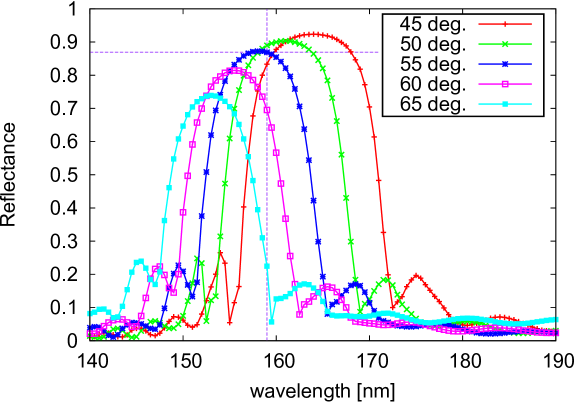
In order to evaluate the reflectance of VUV-OC for p-polarization in the VUV range, we carried out reflectance measurement using a synchrotron light source at UVSOR facility (Okazaki, Japan) BL5B . First, incident VUV power from the storage ring is calibrated by a photodiode (AXUV100, IRD). Then the reflection from the VUV-OC, which was placed on a rotation stage, was measured by the same photodiode. Thus we measured the absolute reflectance shown in Fig. 3 at several incident angles (, , , , and ). Wavelength was changed with a monochromator in the beamline from 140 to 190 nm with a wavelength step of 0.5 nm. At the Brewster angle of , the reflectance of was obtained at 159 nm, and was achieved from 155 to 161.5 nm. We found that the maximum reflectance is higher at the smaller incident angles: at 161 nm () and at 164 nm (). Furthermore, the maximum reflectance at incidence is still as high as at around 153 nm. Thus, this VUV-OC technique is useful in such a broadband VUV range, and can be applicable to outcoupling e.g. the seventh harmonic at around 150 nm generated from Yb-fiber combs at 1040–1060 nm.
III.2 Experimental results of intracavity HHG
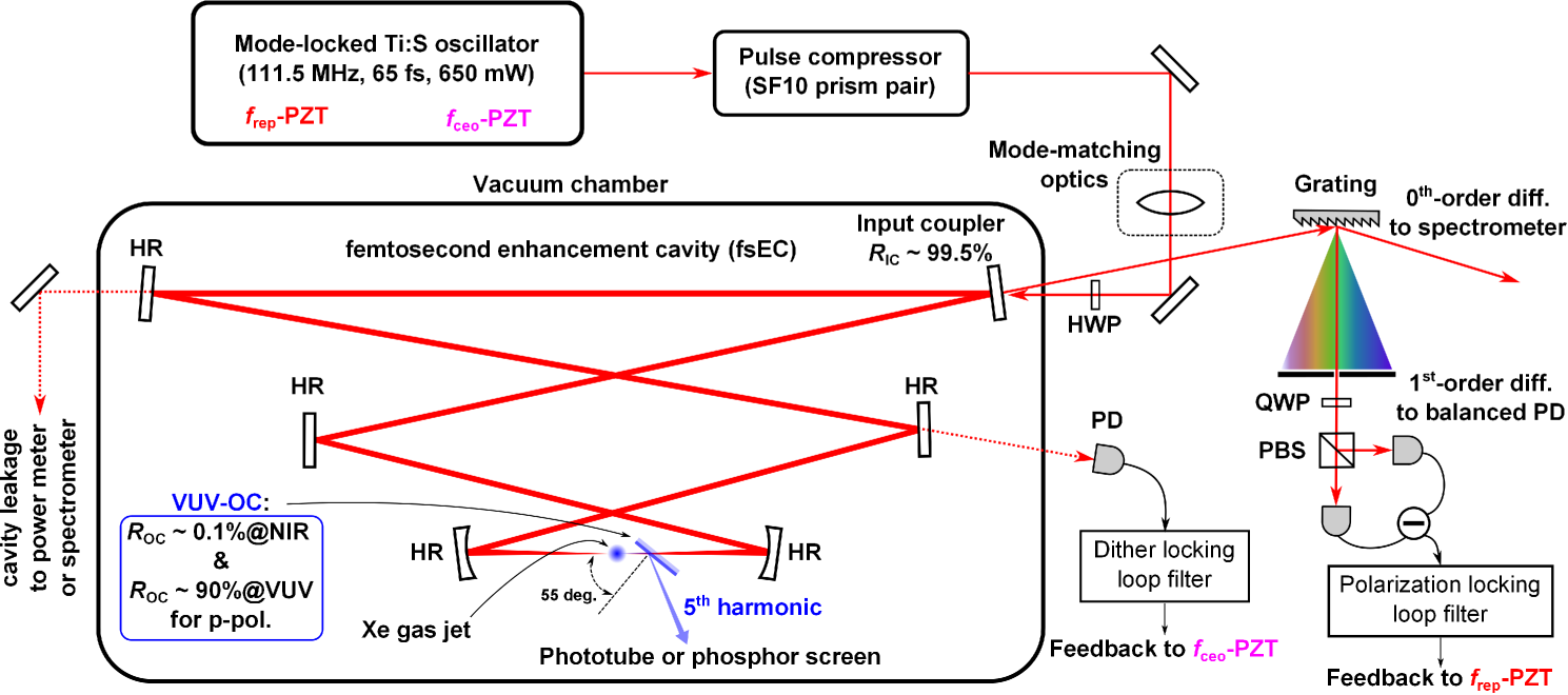
We deployed our VUV-OC in our experimental intracavity HHG setup shown in Fig. 4. A home-made Ti:S oscillator consists of a linear cavity including a prism pair. The center wavelength of fundamental fs combs is tuned to be 795 nm. The repetition rate (), spectral bandwidth, pulse width, and average power are 111.5 MHz, 20 nm, 65 fs and 650 mW, respectively. After dispersion compensation by a pair of SF10 prisms, fs combs are guided into the fsEC placed inside a vacuum chamber. The fsEC consists of six broadband, low-GDD mirrors: an input coupler with a reflectance of , three planar high reflectors (HRs), and two concave HRs with radius of curvatures of 100 mm. Although horizontal and vertical beam waist sizes between the two concave mirrors are slightly different because of aberration caused by the finite folding angle in bow-tie configuration, both of them are evaluated to be about m by beam propagation parameters measured outside the fsEC. The reflection from the input coupler is guided to a diffraction grating. The zeroth-order diffraction from the grating is fiber-coupled and introduced into a spectrometer (USB4000, Ocean Optics) to evaluate reflection spectra from the fsEC. Then the first-order diffraction is used for Hänsch-Couillaud locking technique HClocking80 (referred to as “Polarization locking” in Fig. 4), which adjusts of the Ti:S oscillator to that of the fsEC. The carrier-envelope-offset frequency of the fs comb is controlled so that power inside the fsEC is maximum. Cavity leakage allows us to estimate the power as well as the spectrum of cavity field. The average circulating power inside the fsEC was estimated to be 120 W (maximum), which corresponds to the peak intensity of W/cm2. Xe gas was used as nonlinear media and introduced to the beam waist through a gas-jet nozzle (100 m diameter). We observed visible plasma via ionization of the Xe gas. The VUV-OC is placed at the Brewster angle of incidence right after the major focus of the fsEC. Generated VUV power was measured by a solar-blind phototube (R1187 R1187 , Hamamatsu). The phototube was calibrated at Hamamatsu, and the sensitivity to light at 160.8 nm was measured to be 9 mA/W.
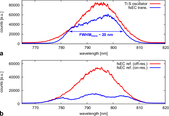
Typical intensity spectra for the fundamental frequency combs are plotted in Fig. 5. The red and blue solid curves in Fig. 5a, are spectra of the Ti:S oscillator and the fsEC transmission (leakage), respectively. The bandwidth of transmitted spectrum is about 20 nm, which we used to evaluate as described in section II. The blue (red) solid curve in Fig. 5b is a reflection spectrum from the fsEC which is on-resonant (off-resonant). We roughly evaluate the frequency-averaged enhancement factor for the fsEC Ozawa08 : obtained with neglecting a frequency-dependent round-trip phase term. Here, where denotes residual reflectance in which we sum up reflectance for all the other mirrors except for the VUV-OC and the fsEC input coupler. We assume that VUV-OC and input coupler are lossless. From the experimentally observed enhancement factor of 350, we estimated to be for all the other five HR mirrors for fsEC. Note, we neglect the GDD effect which might be caused by the VUV-OC. Further precise measurement about frequency-resolved intracavity GDD and/or losses is possible by using several methods Thorpe05 ; Schliesser06 ; Hammond09 .
We then measured the time variation of average power in the VUV comb as shown in Fig. 6a. We tested the two positions of the VUV-OC: (red) 15 mm and (blue) 25 mm away from the fsEC focus. As seen in the figure, the closer VUV-OC position resulted in the faster decay. The decay constants are fitted by using , and we obtained (green) s, and (cyan) s. This decay is associated with the reduction of fundamental power inside the fsEC as can be seen from the Fig. 6b. In contrast, we did not observe any power reduction (shown as the magenta curve) without Xe gas, namely in the absence of high harmonics. One of possible reasons for the degradation in the harmonic yield is VUV-induced IR absorption in our VUV-OC. VUV illumination may cause defects in the VUV-OC which can absorb intense IR beam. This may change GDD in the VUV-OC via accumulation of heat, which is not easily dissipated in vacuum. This degradation was not permanent and the harmonic yield was recovered after certain hours of break time. The similar reversible degradation at IR wavelength has been reported for oxide mirrors illuminated by UV radiation in free-electron-laser systems FELbook09 .
The yield of the fifth harmonic as a function of fundamental power is shown in Fig. 6c. In both cases of (left) 15 mm and (right) 25 mm distance, data are fitted well to as was predicted in section II. We measured the average power of fifth harmonic outcoupled from the fsEC to be W at maximum with a nozzle back pressure of about 1.4 atm. The HHG chamber was evacuated and the pressure inside the chamber was below 10 mTorr when Xe gas was supplied. We previously reported 0.67 W Wakui11 using a diffraction-grating mirror as demonstrated in Yost08 . Thus our VUV-OC outperforms our previous setup, and increased the final yield for nearly ten times. Further optimization of HHG conditions Yost09 ; Carlson11 ; Allison11 ; Lee11 ; Hammond11 might yield power increase of the VUV combs.

Finally, we measured a spatial-mode profile of VUV radiation outcoupled from the fsEC via visible fluorescence emission from a phosphor screen covered with sodium salicylate (Scintillator window, McPherson). The fluorescence emission is peaked at 420 nm Samson_book_67 . Because the VUV radiation is generated at the intracavity focus and reflected by the simple dichroic beamsplitter, the outcoupled VUV radiation should presumably be a clean Gaussian beam. This feature must be one of the indispensable prerequisites so as to realize tight focusing onto a trapped ion. A snapshot of fluorescence intensity observed by a CCD camera (PL-B953U, PixeLINK) is shown in Fig. 7. The measured intensity distribution is a slightly asymmetric two-dimensional (2D) Gaussian.

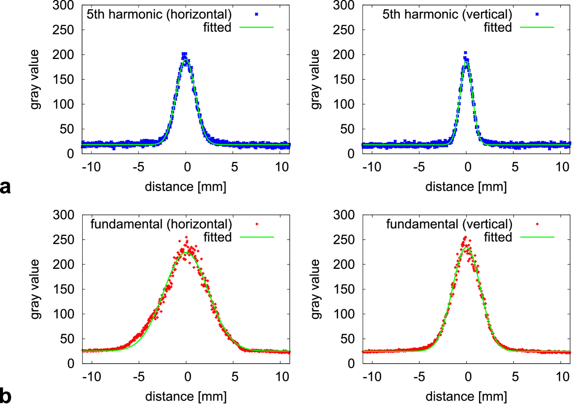
We then fitted the fluorescence intensity and evaluated the spatial-mode profile of the VUV radiation, based on the fact that a quantum efficiency of sodium salycilate is high in the VUV region Allison64 and is almost flat over that wavelength range Johnson51 ; Watanabe53 . We also assume that the sodium salycilate layer was not saturated due to the faint (W-level) average VUV power. The fitting results by using a Gaussian function are shown in Fig. 8a. We obtained (left) mm and (right) mm as a beam radius at the phosphor screen, which is placed at about 140 mm away from the fsEC focus. Thus a beam diameter of the fifth harmonic on the VUV-OC is estimated to be about 1 mm in the case of 25 mm distance. We also evaluated a beam radius of fundamental light by the same CCD camera observing the fundamental light scattered at the same phosphor screen. The fitting results are shown in Fig. 8b, resulting in (left) mm and (right) mm. In such a way we obtained a beam divergence ratio of the fifth harmonic compared to the fundamental as and . According to the theoretical prediction Pupeza13 , the ratio is expected to be , which is in good agreement with the above experimental observation. Thus we confirmed that only the fifth harmonic was successfully outcoupled from the fsEC as the Gaussian beam using our VUV-OC.
IV Conclusion
In conclusion, we have reported a feasibility study on detection of a single trapped In+ at 159 nm VUV wavelength. We estimated a fluorescence photon counting rate per the average VUV power to be cps/W in a realistic experimental condition, in which the ion is irradiated by a quasi-CW VUV beam generated via intracavity HHG. This suggests that an average VUV power of microwatt level suffices for detecting an In+ ion. Toward this goal we have built an intracavity HHG setup for generating VUV radiation using a novel efficient output coupler (VUV-OC). Reflectance of the VUV-OC at an incident angle of was measured to be at 159 nm, and was achieved from 155 to 161.5 nm. Our HHG setup with the VUV-OC has provided an output of W VUV combs around 159 nm with an unexpected exponential decay in power. This power level will yield more than 500 cps detection of fluorescent photons, indicating that quantum state discrimination of the ion is feasible with our present setup, provided that the power decay problem is properly addressed.
With minor modifications and further improvements, our HHG setup can be deployed to a wider range of applications to optical clocks based on ions with two outer elections. A Ti:S oscillator centered at 835 nm can be used for generating VUV radiation at 167 nm as the fifth harmonic in a setup similar to ours, and our VUV-OC approach provides efficient output coupling also at this wavelength as shown in Fig. 3. The 167 nm radiation generated in this way can be used for probing the – transition of Al+. Boosting of the fundamental power up to 1 W is possible with commercially available fs combs, and it gives a peak intensity of W/cm2 in our setup. In this perturbative regime Gohle05 the HHG power scaling can be roughly estimated based on our experimental data shown in Fig. 6c. An average VUV comb power of 50 W is estimated for the 1 W input, corresponding to a detection rate of more than 4000 cps from an In+. This counting rate could dramatically reduce the detection time. Further increase of the fundamental fs comb power can be achieved using an injection locking amplifier Paul08 , but the scaling of the VUV power does not follow the perturbative approximation any more. Nevertheless increase in the VUV power is expected, as has been reported in ref Lee11 , in which XUV radiation of 77 W at 72 nm has been generated as the 11th harmonic of the amplified Ti:S oscillator. In such power level of tens of microwatt, instead of focusing the quasi-CW beam tightly to a single ion, the beam could be loosely focused to illuminate a chain of multiple ions simultaneously along the trapping axis. This might provide a novel detection method for multi-ion optical clocks.
Acknowledgments
The authors thank H. Hachisu, A. Yamaguchi, Y. Li, S. Nagano, H. Ishijima, M. Kumagai, M. Kajita, Y. Hanado and M. Sasaki for discussions and support, and E. Sasaki for technical support. Part of this work was supported by the Use-of-UVSOR Facility Program (BL5B, No. 25-568) of the Institute for Molecular Science.
References
- (1) C. W. Chou, D. B. Hume, J. C. J. Koelemeij, D. J. Wineland, and T. Rosenband, Phys. Rev. Lett. 104, 070802 (2010).
- (2) B. J. Bloom, T. L. Nicholson, J. R. Williams, S. L. Campbell, M. Bishof, X. Zhang, W. Zhang, S. L. Bromley, and J. Ye, Nature 506, 71 (2014).
- (3) I. Ushijima, M. Takamoto, M. Das, T. Ohkubo, H. Katori, arXiv:1405.4071 [physics.atom-ph] (2014).
- (4) H. Dehmelt, IEEE Trans. Instrum. Meas. IM-31, 83 (1982).
- (5) H. Katori, M. Takamoto, V. Pal’chikov, and V. Ovsiannikov, Phys. Rev. Lett. 91, 173005 (2003).
- (6) P. O. Schmidt, T. Rosenband, C. Langer, W. M. Itano, J. C. Bergquist, and D. J. Wineland, Science 309, 749 (2005).
- (7) T. Brabec and F. Krausz, Rev. Mod. Phys. 72, 545 (2000).
- (8) P. B. Corkum and F. Krausz, Nature Phys. 3, 381 (2007).
- (9) R. J. Jones, K. D. Moll, M. J. Thorpe, and J. Ye, Phys. Rev. Lett. 94, 193201 (2005).
- (10) Ch. Gohle, Th. Udem, M. Herrmann, J. Rauschenberger, R. Holzwarth, H. A. Schuessler, F. Krausz, and T. W. Hänsch, Nature 436, 234 (2005).
- (11) K. Hayasaka, Appl. Phys. B 107, 965 (2012).
- (12) N. Herschbach, K. Pyka, J. Keller, T.E. Mehlstäubler, Appl. Phys. B 107, 891 (2012).
- (13) E. Peik and C. Tamm, Europhys. Lett. 61, 181 (2003).
- (14) B. R. Beck, J. A. Becker, P. Beiersdorfer, G. V. Brown, K. J. Moody, J. B. Wilhelmy, F. S. Porter, C. A. Kilbourne, and R. L. Kelley, Phys. Rev. Lett. 98, 142501 (2007).
- (15) W. G. Rellergert, D. DeMille, R. R. Greco, M. P. Hehlen, J. R. Torgerson, and E. R. Hudson, Phys. Rev. Lett. 104, 200802 (2010).
- (16) C. J. Campbell, A. G. Radnaev, and A. Kuzmich, Phys. Rev. Lett. 106, 223001 (2011).
- (17) O. A. Herrera-Sancho, N. Nemitz, M. V. Okhapkin, and E. Peik, Phys. Rev. A 88, 012512 (2013).
- (18) D. Kolbe, M. Scheid, and J. Walz, Phys. Rev. Lett. 109, 063901 (2012).
- (19) T. Kanai, T. Kanda, T. Sekikawa, S. Watanabe, T. Togashi, C. Chen, C. Zhang, Z. Xu, and J. Wang, J. Opt. Soc. Am. B 21, 370 (2004).
- (20) Y. Nomura, Y. Ito, A. Ozawa, X. Wang, C. Chen, S. Shin, S. Watanabe, and Y. Kobayashi, Opt. Lett. 36, 1758 (2011).
- (21) J. Zheng and M. Katsuragawa, arXiv:1406.3921 [quant-ph] (2014).
- (22) J. von Zanthier, Th. Becker, M. Eichenseer, A. Yu. Nevsky, Ch. Schwedes, E. Peik, H. Walther, R. Holzwarth, J. Reichert, Th. Udem, T. W. Hänsch, P. V. Pokasov, M. N. Skvortsov, and S. N. Bagayev, Opt. Lett., 25, 1729 (2000).
- (23) Y. H. Wang, R. Dumke, T. Liu, A. Stejskal, Y. N. Zhao, J. Zhang, Z. H. Lu, L. J. Wang, Th. Becker, and H. Walther, Opt. Commun. 273, 526 (2007).
- (24) http://www.nist.gov/pml/data/asd.cfm
- (25) G. R. Guthöhrlein, M. Keller, K. Hayasaka, W. Lange, and H. Walther, Nature 414, 49 (2001).
- (26) A. J. Caruso, G. H. Mount, and B. E. Woodgate, Appl. Opt. 20, 1764 (1981).
- (27) J. A. R. Samson and D. L. Ederer (eds.), Vacuum Ultraviolet Spectroscopy I (Academic Press, New York, 1998).
- (28) N. Mahajan, J. Opt. Soc. Am. A 22, 1824 (2005).
- (29) A. Cingöz, D. C. Yost, T. K. Allison, A. Ruehl, M. E. Fermann, I. Hartl, and J. Ye, Nature 482, 68 (2012).
- (30) A. Ozawa and Y. Kobayashi, Phys. Rev. A 87, 022507 (2013).
- (31) M. Herrmann, M. Haas, U. Jentschura, F. Kottmann, D. Leibfried, G. Saathoff, Ch. Gohle, A. Ozawa, V. Batteiger, S. Knunz, N. Kolachevsky, H. A. Schussler, T. W. Hänsch, and Th. Udem, Phys. Rev. A 79, 052505 (2009).
- (32) K. Wakui, K. Hayasaka, and T. Ido, Proc. SPIE 8132, Time and Frequency Metrology III, 813204 (2011).
- (33) J. Paul, J. Johnson, J. Lee, and R. J. Jones, Opt. Lett. 33, 2482 (2008).
- (34) A. Ruehl, A. Marcinkevicius, M. E. Fermann, and I. Hartl, Opt. Lett. 35, 3015 (2010).
- (35) D. Yost, T. Schibli, and J. Ye, Opt. Lett. 33, 1099 (2008).
- (36) Y.-Y. Yang, F. Süßmann, S. Zherebtsov, I. Pupeza, J. Kaster, D. Lehr, H.-J. Fuchs, E.-B Kley, E. Fill, X.-M. Duan, Z.-S Zhao, F. Krausz, S. L. Stebbings, and M. F. Kling, Opt. Express 19, 1954 (2011).
- (37) O. Pronin, V. Pervak, E. Fill, J. Rauschenberger, F. Krausz, and A. Apolonski, Opt. Express 19, 10232 (2011).
- (38) I. Pupeza, E. E. Fill, and F. Krausz, Opt. Express 19, 12108 (2011).
- (39) I. Pupeza, S. Holzberger, T. Eidam, H. Carstens, D. Esser, J. Weitenberg, P. Rußbüldt, J. Rauschenberger, J. Limpert, Th. Udem, A. Tünnermann, T. W. Hänsch, A. Apolonski, F. Krausz, and E. Fill, Nature Phys. 7, 608 (2013).
- (40) https://www.uvsor.ims.ac.jp/eng/index.html
- (41) T. W. Hänsch and B. Couillaud, Opt. Commun. 35, 441 (1980).
- (42) http://www.hamamatsu.com/jp/en/index.html
- (43) A. Ozawa, J. Rauschenberger, Ch. Gohle, M. Herrmann, D. Walker, V. Pervak, A. Fernandez, R. Graf, A. Apolonski, R. Holzwarth, F. Krausz, T. W. Hänsch, and Th. Udem, Phys. Rev. Lett. 100, 253901 (2008).
- (44) M. J. Thorpe, R. J. Jones, K. D. Moll, J. Ye, and R. Lalezari, Opt. Express 13, 882 (2005).
- (45) A. Schliesser, Ch. Gohle, Th. Udem, and T. W. Hänsch, Opt. Express 14, 5975 (2006).
- (46) T. J. Hammond, A. K. Mills, and D. J. Jones, Opt. Express 17, 8998 (2009).
- (47) National Research Council, Scientific Assessment of High-Power Free-Electron Laser Technology (The National Academies Press, Washington DC, 2009).
- (48) D. C. Yost, Th. R. Schibli, J. Ye, J. L. Tate, J. Hostetter, M. B. Gaarde, and K. J. Schafer, Nature Phys. 5, 815 (2009).
- (49) D. R. Carlson, J. Lee, J. Mongelli, E. M. Wright, and R. J. Jones, Opt. Lett. 36, 2991 (2011).
- (50) T. Allison, A. Cingöz, D. C. Yost, and J. Ye, Phys. Rev. Lett. 107, 183903 (2011).
- (51) J. Lee, D. R. Carlson, and R. J. Jones, Opt. Express 19, 23315 (2011).
- (52) T. J. Hammond, A. K. Mills, and D. J. Jones, Opt. Express 19, 24871 (2011).
- (53) J. A. R. Samson, Techniques of Vacuum Ultraviolet Spectroscopy (Wiley, New York, 1967).
- (54) R. Allison, J. Burns, and A. J. Tuzzolino, J. Opt. Soc. Am. 54, 747 (1964).
- (55) F. S. Johnson, K. Watanabe, and R. Tousey, J. Opt. Soc. Am. 41, 702 (1951).
- (56) K. Watanabe and E. C. Y. Inn, J. Opt. Soc. Am. 43, 32 (1953).