Acceleration Measurements Using Smartphone Sensors:
Dealing with the Equivalence Principle
Abstract
Acceleration sensors built into smartphones, i-pads or tablets can conveniently be used in the Physics laboratory. By virtue of the equivalence principle, a sensor fixed in a non-inertial reference frame cannot discern between a gravitational field and an accelerated system. Accordingly, acceleration values read by these sensors must be corrected for the gravitational component. A physical pendulum was studied by way of example, and absolute acceleration and rotation angle values were derived from the measurements made by the accelerometer and gyroscope. Results were corroborated by comparison with those obtained by video analysis. The limitations of different smartphone sensors are discussed.
I Statement of the problem
The use of smartphones and similar devices has spread pervasively worldwide over the past years. The scope of the smartphone utility has exceeded that initially envisioned. The smartphone revolution has impacted even teaching practices, as various experiments can be readily carried out using sensors customarily available in smartphones. Several recent works have proposed the use of smartphones in the conduction of laboratory experiments on mechanics Vogt and Kuhn (2012a); Chevrier et al. (2013); Streepey (2013), electromagnetism Silva (2012); Forinash and Wisman (2012), optics Thoms et al. (2013), oscillations Castro-Palacio et al. (2013); Sans et al. (2013) and waves Parolin and Pezzi (2013); Kuhn and Vogt (2013a).
Some such experiments dealt with mechanics problems; specifically, the measurement of gravitation Kuhn and Vogt (2013b), the determination of elastic energy and the study of simple Vogt and Kuhn (2012b), physical, or spring Kuhn and Vogt (2012) pendulums have been addressed. A recent study Shakur and Sinatra (2013) focused on the conservation of the angular momentum using a smartphone equipped with an angular rate sensor, or gyroscope, mounted on a rotating table. The gyroscope sensor has also been used for the calculation of rotational kinetic energy in a physical pendulum Monteiro et al. (2014a).
Acceleration and rotational sensors can be used simultaneously. In one study Monteiro et al. (2014b), a smartphone was placed at different distances from the rotation shaft of measurements of centripetal acceleration and angular velocity of a smartphone placed at different distances from the rotation shaft of a merry-go-round were correlated with the angular radius by means of linear regressions. Likewise, in a recent study of a physical pendulum, a smartphone affixed to a bicycle wheel was subject to both rotational as well as low- and high-amplitude oscillating motion (i.e., spinning in complete circles in one direction, or around a point of stable equilibrium, respectively) Monteiro et al. (2014c). In this study, the sensors provided acceleration and angular velocity measurements with respect to different axes fixed to the smartphone. For this, a relatively simple system with one degree of freedom, a generalized coordinate and the conjugate momentum were determined, enabling the representation of trajectories in the phase space. This latter, somewhat abstract concept was thus rendered more tangible.
Little attention has been paid to the fact that acceleration sensors, when placed in an accelerated system, actually measure an apparent acceleration. The absolute or real acceleration (i.e., relative to the reference frame defined by the laboratory) cannot be readily determined, as it is not possible to discern experimentally between a system subject to a gravitational field and a non-inertial one by virtue of the equivalence principle. In this work, the real acceleration and the angle of rotation of the smartphone were determined based on measurements made by the in-built acceleration and gyroscope sensors. In the experiment, motion in the system occurred in only one plane, with only one degree of freedom. The results obtained from the smartphone were compared with independent determinations made by the analysis of video recordings. As the use of smartphones in the laboratory becomes increasingly widespread, the concepts discussed in this paper can prove useful to both students and instructors.
II Experimental set-up: physical pendulum and sensors
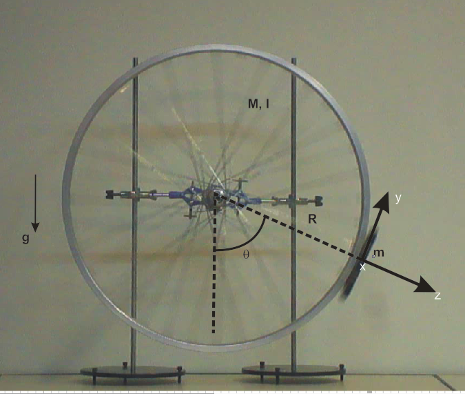
A physical pendulum is defined as a rigid body rotating in a plane around a horizontal axis as a result of the effect of gravity. In this experiment, the physical pendulum is composed of a bicycle wheel with its axis fixed in a horizontal position around which the wheel rotates in a vertical plane, and a smartphone affixed to the outer edge of the tire, as shown in Fig. 1. An Android operated smartphone (LG G2 D805) furnished with a 3-axis LGE accelerometer sensor (STMicroelectronics, 0.001 m/s2 precision) and a 3-axis LGE gyroscope (STMicroelectronics, 0.001 rad/s precision) was used. Technical information regarding the exact location of the sensors within the smartphone was obtained from the manufacturer and verified by physical methods Monteiro et al. (2014c). The Adrosensor application was used to record sensor readings Google (2014).
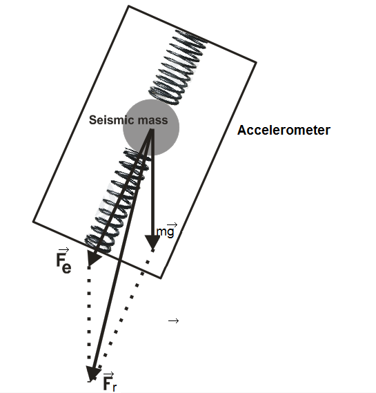
To make full use of the in-built sensors it is necessary to analyze their basic operation principles. The construction characteristics of acceleration sensors are such that they are, actually, force sensors Wikisensors (2014); Vogt and Kuhn (2012a). These sensors measure the normal force exerted on a test particle (or seismic particle) by a piezoelectric ceramic or micromechanical capacitor, as shown in Fig. 2. Thus, to obtain a measurement of the real acceleration of the smartphone it is necessary to subtract the gravitational component (mg), as shown in Figure 2. This transformation can be readily made if the smartphone is at rest or in uniform rectilinear motion. In contrast, if the device is subject to acceleration in an arbitrary direction, supplementary measurements are needed by virtue of the equivalence principle.
In addition to an accelerometer, a gyroscope sensor was used in this experiment. Initially, gyroscopes were based on rotational gimbal-mounted mechanical devices. Today, smartphones are equipped with Micro-machined Electro-Mechanical Systems (MEMS) which measure the Coriolis force on a vibrating body. These sensors provide direct readings of the angular velocity of the smartphone relative to predefined axes fixed in the reference frame of the device.
Also linear acceleration and orientation pseudosensors are available in many smartphone models. Linear acceleration pseudosensors are supposed to provide readings of the acceleration that the device is subject to after subtracting the gravitational component. The orientation pseudosensor integrates the data acquired by several sensors, including a geomagnetic field sensor, to yield a measurement of the orientation of the device. In this paper, the results from the accelerometer and the gyroscope are compared with measurements obtained using these pseudosensors, and the accuracy of the latter discussed.
The components of vectorial magnitudes are usually read on three axes () oriented as if drawn on the smartphone screen. The measurements used in this study were read by the gyroscope sensor on the axis and by the acceleration sensor on the and axes, for tangential and radial acceleration, respectively. The recorded data can be downloaded to a computer and analyzed using suitable software. An independent measurement of the system’s motion was available from video data acquired by a digital camera positioned frontally. The center of the focal field was positioned at the axle of rotation of the wheel in order to minimize parallax error. Based on the distance between the axle and the inner edge of the tire as the length scale, the system’s motion was analyzed with Tracker software Brown (2014).
III Absolute acceleration and rotation angle
The time evolution of the rotation angle measured from the point of stable equilibrium, as shown in Fig. 1, is derived from Newton’s Second Law. Neglecting the friction term, the system’s equation of motion is given by
| (1) |
where is the smartphone mass, is the distance from the center of mass, and is the moment of inertia of the system composed by the wheel and the smartphone.
The acceleration of the smartphone in the laboratory reference frame is
| (2) |
where is the distance from the center of rotation to the center of mass of the smartphone, located in close proximity to the sensors. The selected radial and tangential versors, and , coincide with the and axes, respectively, on the smartphone. The gyroscope sensor for the axis measures directly the angular velocity on that axis Wikisensors (2014), so that
| (3) |
where the sign is due to the orientation of the axes. It should be noted in Fig. 1 that the axis is in the inward direction, while the sense of rotation is given by the value on the axis, which in this case is positive (anticlockwise).
The acceleration value measured by the acceleration sensor, however, is not a measurement of the real acceleration observed in the laboratory but of an apparent acceleration, , resulting from the vectorial sum of the real acceleration and the acceleration associated with a gravitational field in the opposite direction to that of the real gravitational acceleration, as follows
| (4) |
The components of the apparent acceleration measured by the sensor along axes and of the smartphone are
| (5) |
| (6) |
Equations (2), (3) and (6) can be worked out to yield one of the projected positions as a function of the smartphone measurements,
| (7) |
while the other projection, derived from equations (1), (2) and (5), gives
| (8) |
Thus, combining equations (7) and (8), the system’s generalized coordinate can be obtained.
It is worth noting that the denominator of equation (8) is always positive, since the moment of inertia of a system (the wheel and smartphone) is always greater than the moment of inertia of one of its parts, . The limit case where corresponds to a simple pendulum, and equation (8), which is only valid for a physical pendulum, would be indeterminate.
IV Results
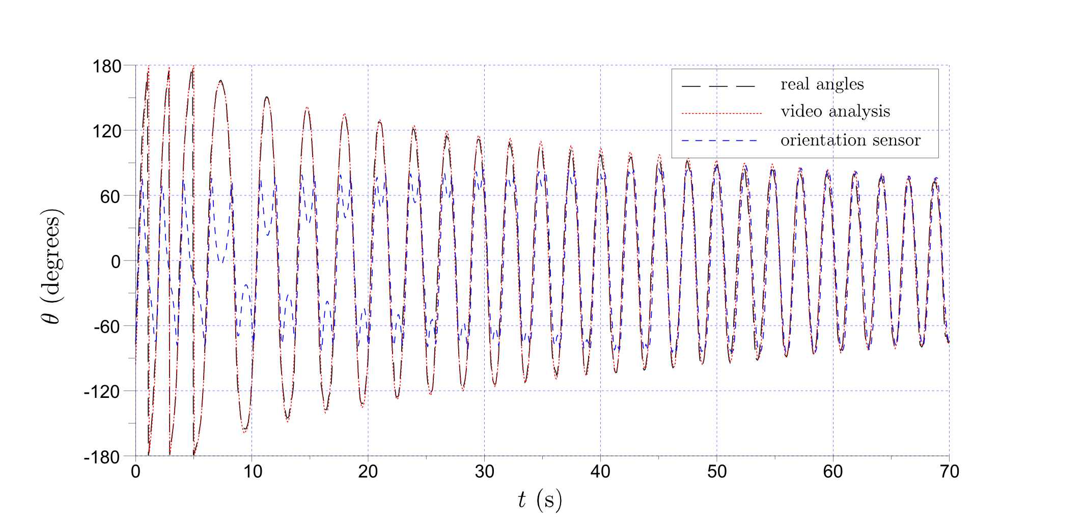
To analyze the system dynamics, the physical pendulum was set in motion with sufficient energy to rotate in complete cycles in one direction. The movement was recorded using the sensors fitted in the smartphone as well as the video recorder. Figure 3 shows the time evolution of both the rotation angle calculated by equations (7) and (8) as well as that obtained by video analysis using Tracker. A third measurement read by the orientation pseudosensor is also shown. The procedure described in the above section yielded results in agreement with measurements resulting from the analysis of video data throughout the experiment. The measurements made by the orientation sensor were in agreement with these results only for angles below 90, a fact ascribed to the definition of axes in the orientation pseudosensor.
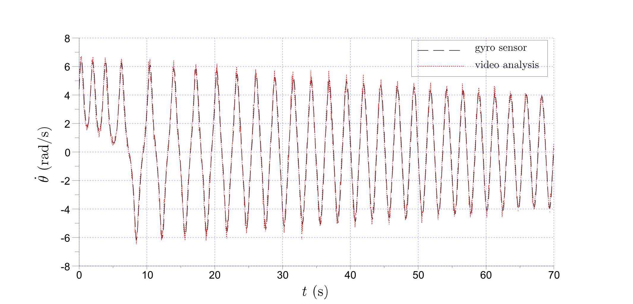
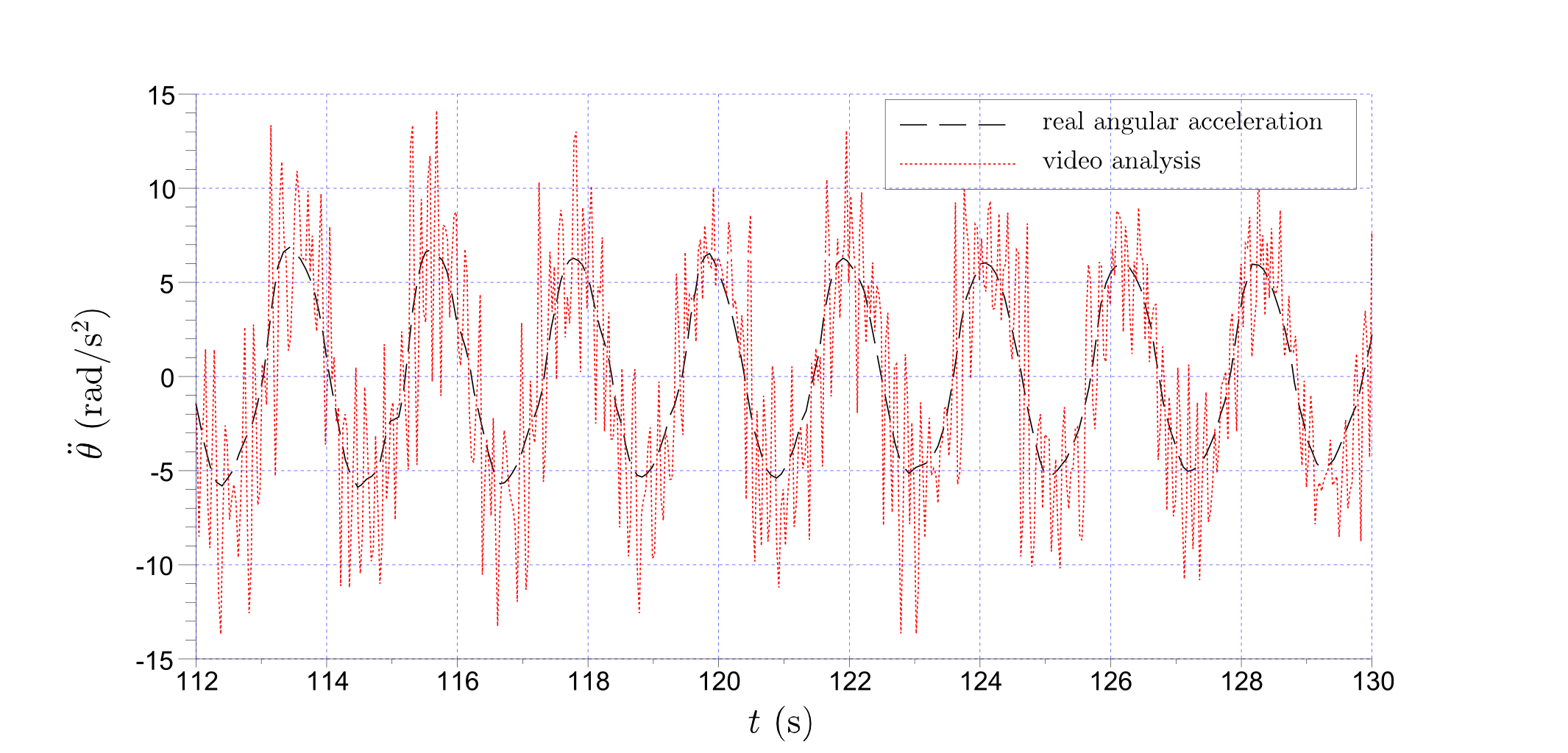
Values of angular velocity and acceleration as a function of time read by the gyroscope sensor and those determined by video analysis are shown in Fig. 4. Using the gyroscope sensor, angular velocity is directly read by the sensor whereas the analysis of video required the numerical calculation of the derivative of the angle. Angular accelerations shown in the figure (bottom panel) corroborate the overall agreement between both procedures. However, the numerical calculation of the derivative, the loss of precision due to the acquisition time of the digital camera and the task of locating the object on each image introduce a noise component in the data of angular velocity and, especially, acceleration, compared with the measurements made directly by the gyroscope sensor.
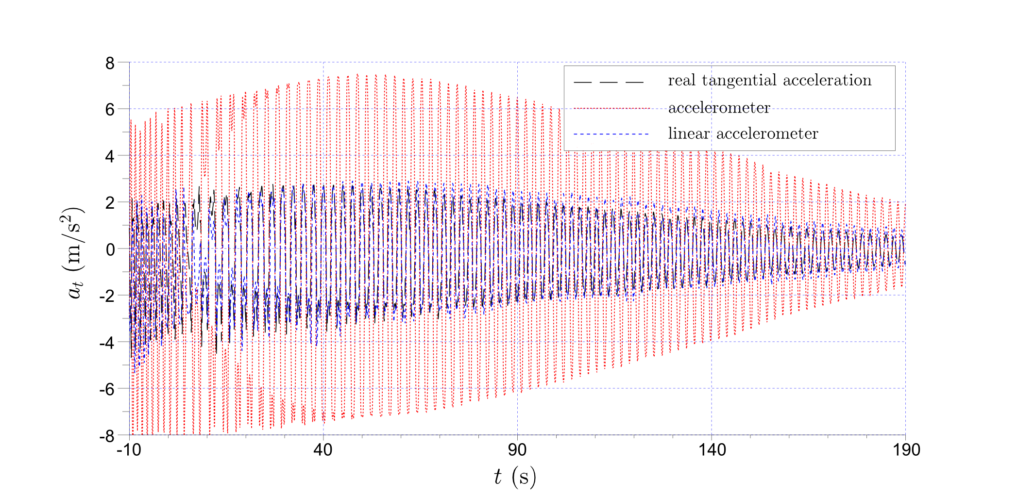
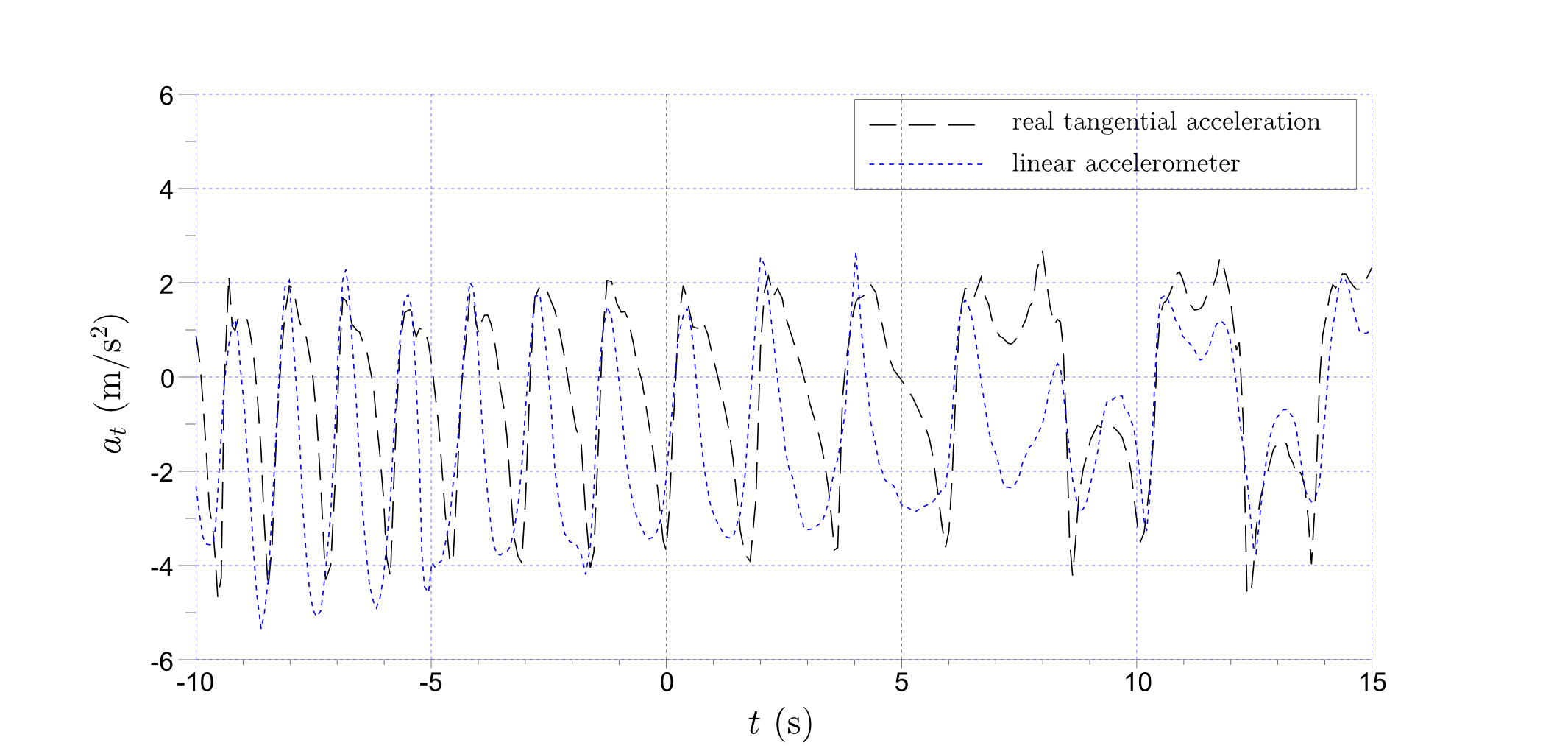
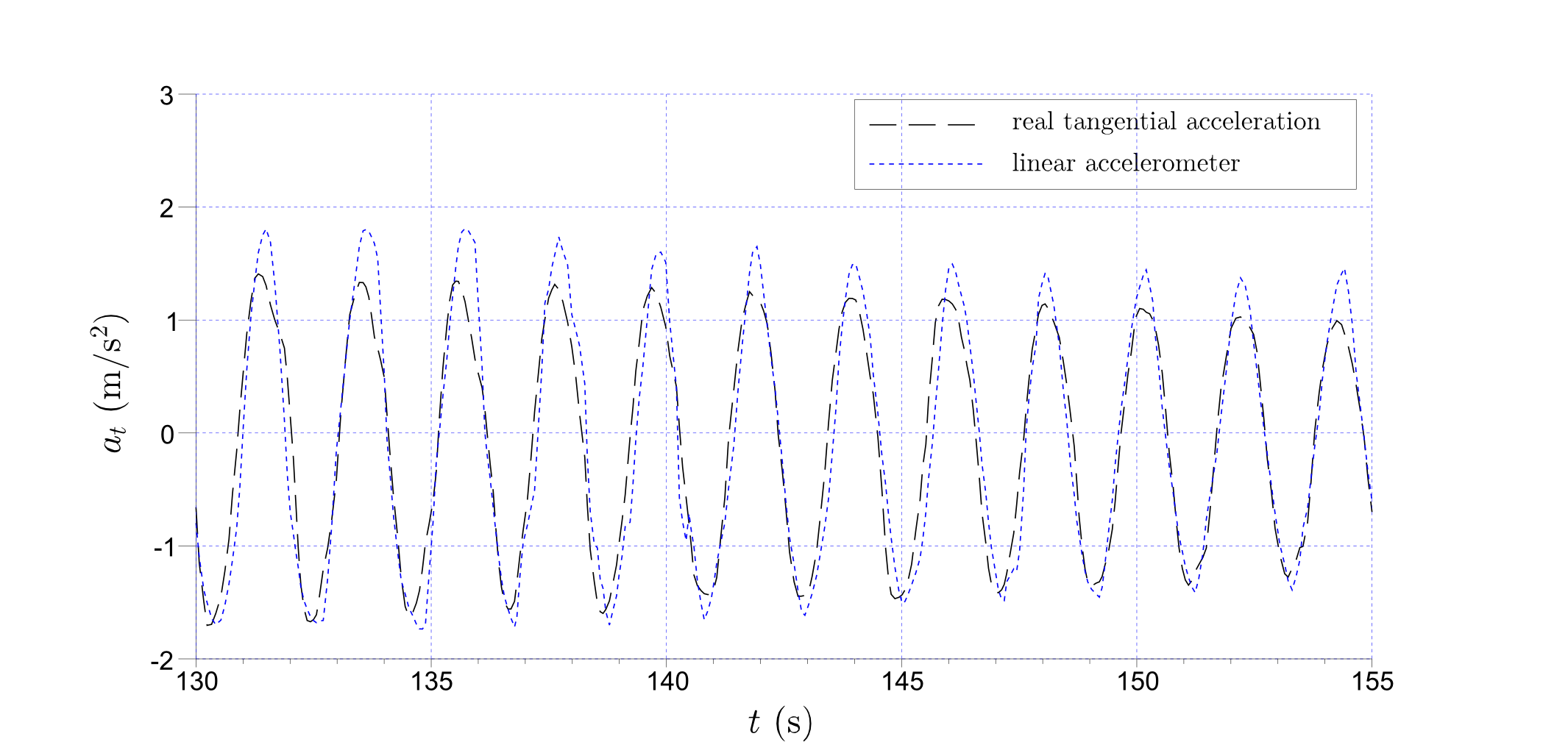
The radial and tangential acceleration components derived from the above equations were compared with the linear acceleration reading from the pseudosensor and the apparent acceleration from the accelerometer, as shown in Figs. 5 and 6. Figure 5 shows the evolution of the tangential acceleration throughout the experiment. The time interval around t=0, where the wheel first comes to a halt and begins to oscillate, and an interval around a later point in time, when the wheel oscillates with intermediate amplitude, are enlarged for illustration purposes. As expected, the apparent acceleration differs clearly from the real acceleration calculated according to the procedure described in the previous section. Likewise, readings from the linear acceleration pseudosensor were found to be inaccurate, in particular when the smartphone moves in proximity to the point of stable equilibrium.
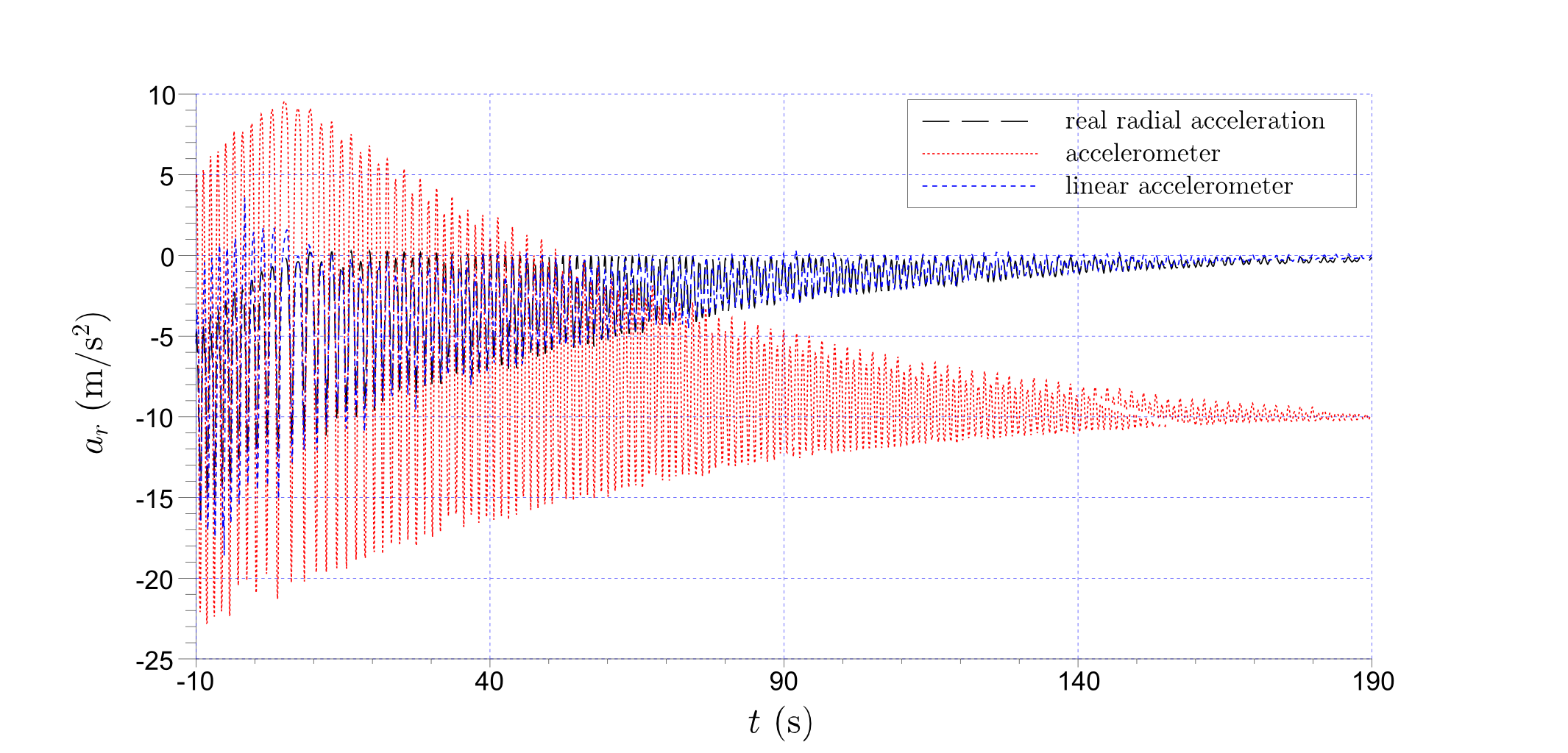
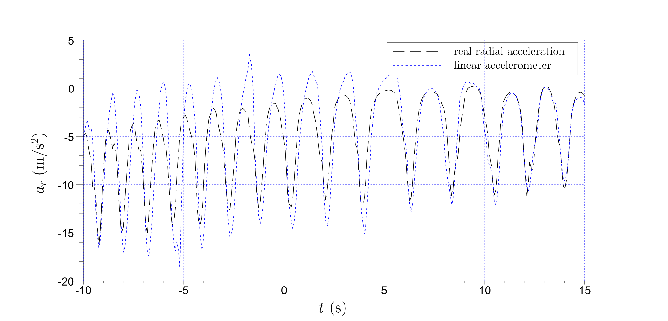
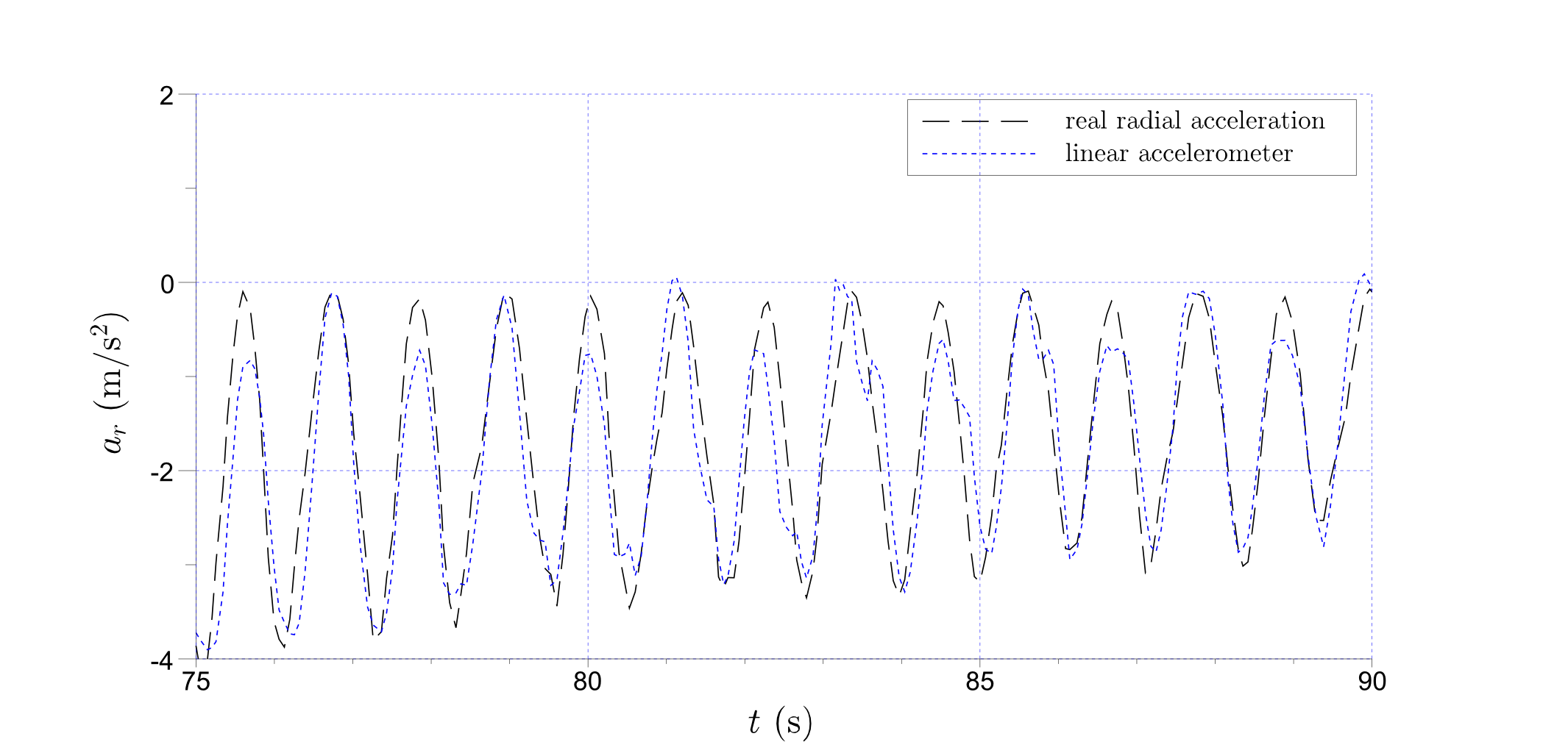
Figure 6 shows the radial acceleration as a function of time. As was the case with the tangential acceleration, the calculated absolute acceleration was found to differ from that read by the sensors. Panel (a) shows that the accelerometer reading tends to -10 when the wheel is motionless, whereas both the calculated acceleration value and that read by the linear accelerometer correctly tend to zero. As shown in panels (b) and (c), readings from the pseudosensor were inaccurate.
V Conclusions and Prospects
This paper describes how measurements made using acceleration and gyroscope sensors fitted in smartphones can be used to obtain the rotation angle and real acceleration of a physical pendulum. Despite the constraints resulting from application of the equivalence principle, these measurements can be complemented with those from the gyroscope sensor to yield real acceleration values. This procedure can be corroborated by comparison with independent measurements determined by video analysis.
Diverse measurements can be made using sensors built into smartphones to elucidate a wide range of physical phenomena. An adequate understanding of the underlying operation principles can shed important light on the appropriate use of these applications, a fact which gains in significance as the use of smartphones becomes more widespread with the expected decrease in cost.
References
- Vogt and Kuhn (2012a) P. Vogt and J. Kuhn, The Physics Teacher 50, 182 (2012a).
- Chevrier et al. (2013) J. Chevrier, L. Madani, S. Ledenmat, and A. Bsiesy, The Physics Teacher 51, 376 (2013).
- Streepey (2013) J. W. Streepey, The Physics Teacher 51, 54 (2013).
- Silva (2012) N. Silva, The Physics Teacher 50, 372 (2012).
- Forinash and Wisman (2012) K. Forinash and R. F. Wisman, The Physics Teacher 50, 242 (2012).
- Thoms et al. (2013) L.-J. Thoms, G. Colicchia, and R. Girwidz, The Physics Teacher 51, 440 (2013).
- Castro-Palacio et al. (2013) J. C. Castro-Palacio, L. Velázquez-Abad, M. H. Giménez, and J. A. Monsoriu, American Journal of Physics 81, 472 (2013).
- Sans et al. (2013) J. Sans, F. Manjón, A. Pereira, J. Gomez-Tejedor, and J. Monsoriu, European Journal of Physics 34, 1349 (2013).
- Parolin and Pezzi (2013) S. O. Parolin and G. Pezzi, The Physics Teacher 51, 508 (2013).
- Kuhn and Vogt (2013a) J. Kuhn and P. Vogt, The Physics Teacher 51, 118 (2013a).
- Kuhn and Vogt (2013b) J. Kuhn and P. Vogt, European Journal of Physics Education 4 (2013b).
- Vogt and Kuhn (2012b) P. Vogt and J. Kuhn, The Physics Teacher 50, 439 (2012b).
- Kuhn and Vogt (2012) J. Kuhn and P. Vogt, The Physics Teacher 50, 504 (2012).
- Shakur and Sinatra (2013) A. Shakur and T. Sinatra, The Physics Teacher 51, 564 (2013).
- Monteiro et al. (2014a) M. Monteiro, C. Cabeza, and A. C. Martí, The Physics Teacher 52, 561 (2014a).
- Monteiro et al. (2014b) M. Monteiro, C. Cabeza, A. C. Marti, P. Vogt, and J. Kuhn, The Physics Teacher 52, 312 (2014b).
- Monteiro et al. (2014c) M. Monteiro, C. Cabeza, and A. C. Martí, European Journal of Physics 35, 045013 (2014c).
- Google (2014) P. Google, “http://play.google.com, last visited,” (2014).
- Wikisensors (2014) Wikisensors, “http://sensorwiki.org, last visited,” (2014).
- Brown (2014) D. Brown, “http://www.cabrillo.edu/ dbrown/tracker/ last visited,” (2014).