Successive Optimization Tomlinson-Harashima Precoding Strategies for Physical-Layer Security in Wireless Networks
Abstract
In this paper, we propose successive optimization non-linear
precoding strategies for physical-layer security in wireless
networks. We also investigate different precoding techniques for
multi-user MIMO systems under various conditions of channel state
information (CSI) between the access point and the users and the
eavesdroppers. A non-linear precoding technique based on Successive
Optimization Tomlinson-Harashima Precoding (SO-THP) and Simplified
Generalized Matrix Inversion (S-GMI) technique is proposed along
with a strategy for injecting artificial noise prior to
transmission. Simulation results show that the proposed SO-THP+S-GMI
precoding technique outperforms existing non-linear and linear
precoding algorithms in terms of
BER and secrecy rate performances.
Index Terms:
Physical-layer security techniques, precoding, transmit processing.I Introduction
Data security in wireless systems has been dominated in the past by encryption methods like Data Encryption Standard (DES) and Advanced Encryption Standard (AES) which have played very important roles in the security aspects of data transmission. However, these encryption algorithms suffer from high complexity and latency. This has motivated the investigation of novel secrecy techniques which can be implemented in the physical layer and which are under consideration to provide secure wireless transmission.
In the 1970s, Wyner posed the Alice-Bob-Eve problem and proposed the wire-tap transmission system in [1]. The wire-tap transmission system gives a basic description on how to achieve the secrecy in the physical layer with better Gaussian channels between users than the Gaussian wire-tap channel. Later on another study reported in [2] showed that secrecy transmission is possible even when the eavesdropper has a better channel to the transmitter in a statistical sense than the receiver with confidential messages. The secrecy capacity [3] for different kinds of channels, such as the Gaussian wire-tap channel, the MIMO wire-tap channels have been studied in [3] and [4]. In some later works [5], [7], it has been found that by adding artificial noise to the system the secrecy of the transmission can be further enhanced.
I-A Related Work
In recent years, precoding techniques have been widely applied to multi-user MIMO systems. Precoding techniques rely on pre-processing the transmitted data with the help of channel state information (CSI). Different kinds of linear precoding techniques such as Zero-forcing (ZF) precoding, Minimum Mean Square Error (MMSE) precoding and Block Diagonalization (BD) precoding are introduced in [8]-[12], respectively. Some non-linear precoding techniques like Tomlinson-Harashima precoding (THP) [13], Vector Perturbation (VP) precoding [14] have also been reported. The precoding techniques can also contribute to the performance of relay systems [9] These precoding techniques have been proven effective in improving the sum-rate and the bit-error rate (BER) performances. However, precoding strategies require CSI at the transmit side, whereas in reality CSI is available to the users of interest but is rarely available to the eavesdroppers. In most situations, a designer only has access to imperfect CSI for the users of interest. Dealing with imperfect CSI and the absence of CSI of the eavesdropper is a major challenge. Moreover, a technique that is particularly effective for improving the secrecy rate of physical-layer security is the introduction of artificial noise at the transmitter [5].
I-B Contributions
In this pape we propose a novel non-linear technique based on Successive Optimization Tomlinson-Harashima Precoding (SO-THP) and Simplified Generalized Matrix Inversion (S-GMI) techniques along with a strategy of injecting artificial noise prior to transmission. We also study precoding techniques for multi-user MIMO systems under various conditions of CSI between the access point and the users and the eavesdroppers. Simulation results show that the proposed SO-THP+S-GMI precoding technique outperforms existing non-linear and linear precoding algorithms in terms of physical layer secrecy rate performances.
The remainder of this paper is organized as follows. In Section II, the system model and the performance metrics are given. The proposed SO-THP+S-GMI precoding algorithm is introduced in Section III. In Section IV, we discuss the simulation results. The conclusions are given in Section V.
Notation: Bold uppercase letters denote matrices with size and bold lowercase letters denote column vectors with length . Conjugate, transpose, and conjugate transpose are represented by , and respectively; is the identity matrix of size ; denotes a diagonal matrix with the elements of the vector along its diagonal; represents entries with zero mean and variance.
II System Model and Performance Metrics
In this section we introduce the system model considered for the transmission as well as the performance metrics that are used in the evaluation of the precoders.
II-A System Model

Here we consider an uncoded multi-user multiple input multiple output (MU-MIMO) broadcast channel. At the Acess Point (AP) a transmitter with antennas is used to transmit users’ data steams. Each user’s data streams are received with receive antennas. Along with the T users, eavesdroppers each with receive antennas also receive data from the transmitter. In this system we assume the eavesdroppers do not jam the transmission and each user’s or eavesdropper’s channel is a flat-fading MIMO channel. The quantity and corresponds to each user’s or the eavesdropper’s channel matrix. The Gaussian noise with entries is distributed as and .
In the scenarios without artificial noise, each user’s or eavesdropper’s received data are described by
| (1) |
in (1) is used to guarantee that the transmit power after precoding is the same as the original transmit power of user and is the precoding matrix. We use the vector to represent the signal after precoding. Without artificial noise is given by
| (2) |
where is the transmit symbols.
If the artificial noise is applied before the transmission, following the description in [7], the signal after precoding is given by
| (3) |
where , are the precoding matrices. The vector represents the information to be transmitted. The vector is the jamming signal. Suppose is the fraction of the power devoted to the information signal and . The artificial noise then should satisfy
| (4) |
| (5) |
In (4) and (5) is the covariance matrix associated with the jamming signal . The covariance matrix of the transmit signal satisfies
| (6) |
and proper artificial noise power ratio will result in an increase of the secrecy rate. Based on the construction of the artificial noise, there will be a different effect on the secrecy rate performance. In [22], it shows a generalized artificial noise with more flexible covariance matrix to improve the secrecy rate. Besides the construction introduced in [7], the study in [20] reports a system with a helping interferer to improve the achievable secrecy rate.
II-B Performance Metrics
From [1]-[4], we have the definition of the secrecy capacity as the maximum transmission rate Alice can achieve during the transmission without any information detected by the eavesdropper. From [4] without artificial noise, we have the secrecy capacity
| (7) |
In (7) and represent the mutual information between the transmitter to the user as well as the eavesdropper. are the counterparts of different signal symbols. is the covariance matrix associated with the signal after precoding . The secrecy capacity achieved in this situation with prior knowledge of the users’ channel as well as the eavesdroppers’ channel can be used as a benchmark for further study. In reality the channel between the transmitter and the eavesdroppers is not perfectly known. This situation known as the imperfect CSI is discussed in [5]. However, for the imperfect CSI we suppose the distribution of the eavesdroppers’ channel is known to the transmitter and users.
Another performance metric is the BER estimated by the different links. Ideally, we would like the users to experience a reliable communication and the eavesdropper to have a very high BER (virtually no reliability when communicating). In this paper, different precoding techniques are supposed to suppress the interferences between different users thus leading to a better BER performance.
Thirdly, the algorithm computational complexity should also take into consideration. With the increasing of the number of users, the high computational complexity algorithm will suffer from a long time delay. Low computational complexity will contribute to reduce the latency of the system.
III Proposed Precoding Algorithms
In this section, we detail the proposed precoding algorithms.
III-A SO-THP Precoding
According to [21], we assume the modified date symbol vector , where and . With the feedback matrix we can then obtain the output of the modulo operation
| (8) |
where . When we have the feedforward matrix , the transmit signal can be obtained as . where The received signal then can be written in the following form:
| (9) |
In [15], the SO-THP algorithm is illustrated as a combination of a successive optimization technique and Tomlinson-Harashima precoding. The reordered feedforward and feedback matrices are expressed as
| (10) |
| (11) |
where the complex unitary matrix .
III-B S-GMI Precoding
The concept of generalized matrix inversion precoding has been introduced in [16], where two approaches called Generalized Zero-Forcing Channel Inversion (GZI) and Generalized MMSE Channel Inversion (GMI) are illustrated. The GMI scheme uses the QR decomposition to decompose the MMSE channel inversion as expressed by
| (12) |
| (13) |
where , , and GMI takes the noise into account. It overcomes the noise enhancement in the BD algorithm. Meanwhile extra interference may be introduced in the following steps. To solve this problem, a transmit combining matrix is applied to . Under the total transmit power constraint we use the minimum total MSE criterion to achieve the transmit combining matrix . In [16] the transmit combining matrix is given by as described by
| (14) |
where , . Once we have and , the following approach is
| (15) |
In [17], it has been shown that the transmit combining matrix is not necessary. Therefore, a simplified GMI (S-GMI) is developed in [17] as an improvement of the original RBD precoding in [8]. This is known as S-GMI. Therefore, the decomposition in (15), the precoder and the receive filter are
| (16) |
| (17) |
| (18) |
where , . In the SO-THP+S-GMI algorithm, the feedforward matrix (10) is obtained by reordering the S-GMI precoding matrix (17).
IV Simulation Results
A system with transmit antennas and users as well as eavesdroppers is considered. All the transmitted symbols are modulated with QPSK. In the simulations, we assume that the channel for each user is uncorrelated and is generated following a complex Gaussian model with zero mean and variance equal to one.
IV-A Computational complexity
In assessing the computational complexity, the number of FLOPS (Floating-Point Operations Per Second) is used as a measurement of the cost of an algorithm. In [18], the FLOPS for real QR, SVD and complex QR algorithms are given. According to [19] for an complex matrix ,the FLOPS of the SVD of the complex matrix are equivalent to its extended real matrix. The number of FLOPS of the multiplication, the QR decomposition, the matrix inversion as well as SVD with different matrices obtained have been reported in [18].
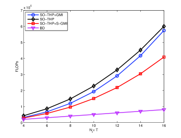
In Fig. 2 it is shown that although the BD precoding algorithm has the lowest complexity, its BER and secrecy rate performances are not satisfactory. Among the SO-THP type algorithms the SO-THP+S-GMI algorithm shows an advantage over the standard SO-THP algorithm in terms of complexity.
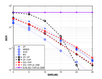
IV-B Perfect Channel State Information
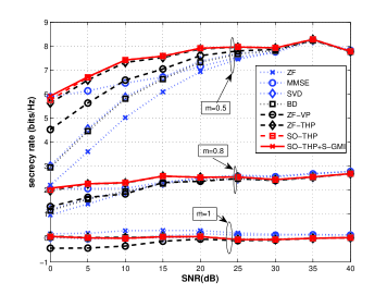
Fig. 3 shows the BER performance for different precoding techniques. The proposed SO-THP+S-GMI precoding requires less than 5 dB than the original SO-THP precoding in terms of SNR to achieve bit error rate. According to Fig. 4, the secrecy rate will level out according to the ratio between the main channel and the wire-tap channel . From Fig. 4, we can also see that among all the investigated precoding algorithms, the proposed SO-THP+S-GMI precoding can achieve a certain secrecy rate with lower SNR.
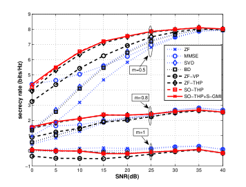
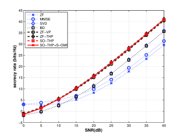
IV-C Imperfect Channel State Information
In Fig. 5, the secrecy rate performance is evaluated in the imperfect CSI scenario, which shows a degradation at low SNR. Furthermore, the secrecy rate requires a very high SNR to converge to a high secrecy rate. The proposed SO-THP+S-GMI precoder has the best secrecy rate performance among all the studied precoding techniques.
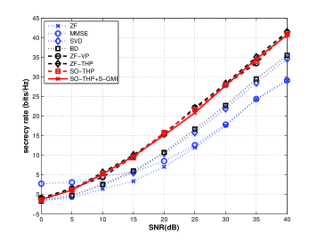
IV-D Imperfect Channel State Information With Artificial Noise
In Fig. 6 and Fig. 7, we assume that artificial noise is generated with extra free antennas. Although the artificial noise is added, the total transmit power will remain the same. In the simulation of the transmit power is used to generate the artificial noise. In Figure 6, with higher SNR, we can have better secrecy rate performance. Even when the eavesdropper has better statistical channel, the secrecy rate keeps almost the same according to Figure 7.
V Conclusion
Precoding techniques used in MU-MIMO broadcast systems can achieve good BER and secrecy-rate performances. The proposed SO-THP+S-GMI algorithm requires the lowest computational complexity among non-linear techniques and outperforms most linear and non-linear techniques in BER performance. Moreover, SO-THP+S-GMI can achieve a high secrecy rate, which means the security of the transmission with SO-THP+S-GMI is superior to existing techniques. When artificial noise is added, the performance is further improved.
References
- [1] A. D. Wyner, “The wire-tap channel”, Bell Syst. Techn. J., Vol. 54, No. 8, Oct. 1975, pp. 1385–1357.
- [2] I. Csiszar and J. K ´ orner, “Broadcast channels with confidential messages” , IEEE Trans. Information Theory, Vol. 24, No. 3, May 1978, pp. 339–348.
- [3] S. Leung-Yan-Cheong, M. Hellman, “The Gaussian wire-tap channel”, IEEE Trans. Information Theory, Vol. 24, No. 4, July 1978, pp. 451-456.
- [4] F. Oggier, B. Hassibi,“ The secrecy capacity of the MIMO wiretap channel”, IEEE International Symposium. Information Theory, July 2008, pp. 524-528.
- [5] S. Goel, R. Negi, “Guaranteeing Secrecy using Artificial Noise”, IEEE Trans. Wireless Communications, Vol. 7, No. 6, June 2008, pp. 2180-2189.
- [6] R. C. de Lamare and R. Sampaio-Neto, “Reduced-Rank Space-Time Adaptive Interference Suppression With Joint Iterative Least Squares Algorithms for Spread-Spectrum Systems, IEEE Transactions on Vehicular Technology, vol. 59, no. 3, March 2010, pp. 1217-1228.
- [7] A. Mukherjee, A.L. Swindlehurst, “Jamming Games in the MIMO Wiretap Channel With an Active Eavesdropper”, IEEE Trans. Signal Processing, Vol. 61, No. 1, Jan 2013, pp. 82-91.
- [8] V. Stankovic, M. Haardt, “Generalized Design of Multi-User MIMO Precoding Matrices”, IEEE Trans. Wireless Communications, Vol. 7, No. 3, March 2008, pp. 953-961.
- [9] Y. Cai, D. Le Ruyet, R. C. de Lamare, D. Roviras, “Linear precoding based on switched relaying processing for multiuser MIMO relay systems”, IEEE 12th International Workshop, Signal Processing Advances in Wireless Communications (SPAWC), June 2011, pp. 351-355.
- [10] Y. Cai, R. C. de Lamare and R. Fa, “Switched interleaving techniques with limited feedback for interference mitigation in DS-CDMA systems”, IEEE Transactions on Communications, vol. 59, no. 7, pp. 1946-1956, July 2011.
- [11] Y. Cai, R. C. de Lamare and D. Le Ruyet, “Transmit processing techniques based on switched interleaving and limited feedback for interference mitigation in multiantenna MC-CDMA systems”, IEEE Transactions on Vehicular Technology, vol. 60, no. 4, 2011, pp. 1559-1570.
- [12] G. Geraci, M. Egan, J. Yuan, A. Razi, I. B. Collings, “Secrecy Sum-Rates for Multi-User MIMO Regularized Channel Inversion Precoding”, IEEE Trans. Communications, Vol. 60, No. 11, November 2012, pp. 3472-3482.
- [13] M. Payaro, A. Perez-Neira, M.A. Lagunas, “Achievable rates for generalized spatial Tomlinson-Harashima precoding in MIMO systems”, 2004 IEEE 60th Vehicular Technology Conference, Vol. 4, pp. 2462 - 2466.
- [14] M. Mazrouei-Sebdani, W.A. Krzymien,“ Vector Perturbation Precoding for Network MIMO: Sum Rate, Fair User Scheduling, and Impact of Backhaul Delay”, IEEE Trans. Vehicular Technology, Vol. 61, Issue. 9, pp. 3946 - 3957.
- [15] V. Stankovic, M. Haardt, “Successive optimization Tomlinson-Harashima precoding (SO THP) for multi-user MIMO systems”, IEEE International Conference, Proceedings. (ICASSP ’05), Vol.3, March 2005, pp.iii/1117 - iii/1120.
- [16] S. Hakjea, L. Sang-Rim, L. Inkyu,“ Generalized channel inversion methods for multiuser MIMO systems”, IEEE Trans. Communications, Vol. 57, Issue. 11, pp. 3489 - 3499.
- [17] K. Zu, R. C. de Lamare and M. Haart, “Generalized design of low-complexity block diagonalization type precoding algorithms for multiuser MIMO systems”, IEEE Trans. Communications, 2013.
- [18] G.H. Golub and C.F. Van Loan, Matrix Computations, John Hopkins Studies in the Math. Sciences, third ed. Johns Hopkins Univ. Press, 1996.
- [19] K. Zu, R. C. de Lamare, “Low-Complexity Lattice Reduction-Aided Regularized Block Diagonalization for MU-MIMO Systems”, IEEE. Communications Letters, Vol. 16, No. 6, June 2012, pp. 925-928.
- [20] A. Chorti, H.V. Poor, “Achievable secrecy rates in physical layer secure systems with a helping interferer”, International Conference on Computing, Networking and Communications (ICNC), Feb 2012, pp. 18-22.
- [21] M.B. Shenouda, T.N. Davidson, “Tomlinson-Harashima Precoding for Broadcast Channels with Uncertainty”, IEEE Journal on Selected Areas in Communications, Vol. 25, No. 7, September 2007.
- [22] P.H. Lin, S.H. Lai, S.C. Lin“On Secrecy Rate of the Generalized Artificial-Noise Assisted Secure Beamforming for Wiretap Channels”, IEEE Journal on Selected Areas in Communications, Vol. 31, No. 9, September 2013.
- [23] K. Takeda, H. Tomeba, F. Adachi“BER Performance Analysis of Joint Tomlonson-Harashima Precoding and Frequency-domain Equalization”, IEEE Communications Society, WCNC 2007 proceedings.
- [24] K. Zu, R. C. de Lamare and M. Haardt, ”Multi-branch Tomlinson-Harashima precoding design for MU-MIMO systems: Theory and algorithm,” IEEE Trans. Commun. (2nd round review), 2013.
- [25] C. Wang, E.K.S. Au, R.D. Murch, W.H. Mow, R.S. Cheng, V. Lau“On the Performance of the MIMO Zero-Forcing Receiver in the Presence of Channel Estimation Error”, IEEE Trans. Communications, Vol. 6, No. 3, March 2007
- [26] H. Yao, Wornell, W.Gregory “Practical Secrecy using Artificial Noise”, IEEE. Communications Letters, vol. 17, no. 7, May 2013, pp. 1483-1486.
- [27] S. Liu, Y. Hong, E. Viterbo, “Lattice-reduction-aided detectors for MIMO communication systems”, Global Telecommunications Conference, 2002, vol. 1, Nov 2002, pp. 424-428.
- [28] A. K. Lenstra, H. W. Lenstra, and L. Lov´asz, “Factoring polynomials with rational coefficients”, Math. Ann, vol. 261, 1982, pp. 515 - 534.
- [29] Y. H. Gan, C. Ling, and W. H. Mow, “Complex lattice reduction algorithm for low-complexity full-diversity MIMO detection”, IEEE Trans. Signal Processing, vol. 57, no. 7, Jul 2009, pp. 2701 - 2710.