On The Impact of Time-Varying Interference-Channel on the Spatial Approach of Spectrum Sharing between S-band Radar and Communication System
Abstract
Spectrum sharing is a new approach to solve the congestion problem in RF spectrum. A spatial approach for spectrum sharing between radar and communication system was proposed, which mitigates the radar interference to communication by projecting the radar waveform onto null space of interference channel, between radar and communication system [1]. In this work, we extend this approach to maritime MIMO radar which experiences time varying interference channel due to the oscillatory motion of ship, because of the breaking of sea/ocean waves. We model this variation by using the matrix perturbation theory and the statistical distribution of the breaking waves. This model is then used to study the impact of perturbed interference channel on the spatial approach of spectrum sharing. We use the maximum likelihood (ML) estimate of target’s angle of arrival to study the radar’s performance when its waveform is projected onto the null space of the perturbed interference channel. Through our analytical and simulation results, we study the loss in the radar’s performance due to the null space projection (NSP) of its waveform on the perturbed interference channel.
Index Terms:
MIMO radar, null space, spectrum sharing, perturbed interference channel, coexistence.I Introduction
Spectrum sharing between radars and communication system is a new way forward to solve the growing problem of spectrum congestion [2]. The 3550-3650 MHz band is identified for spectrum sharing between military radars and broadband wireless access (BWA) communication systems, in the National Telecommunications and Information Administration’s (NTIA) 2010 Fast Track Report [3].
Electromagnetic interference (EMI) to radars and BWA systems is expected from spectrum sharing [4]. In this paper, we focus on mitigating radar’s interference to communication systems. The emission pattern of radar, especially high transmit power and high-peak sidelobes, saturates communication system receiver, which traditionally operate at very small power levels. However, radar’s interference can be mitigated at communication systems by exploiting the advancements in transmitter and receiver designs, and through a combination of spatial and temporal signal processing algorithms.
Spatial algorithms for interference mitigation is a well explored topic in the cognitive radio research community [5], however, a spatial algorithm to mitigate radar’s interference to communication system was first proposed in [1]. The waveform of radar is projected onto null space of interference channel between the radar and the communication system. This NSP of the radar waveform mitigates radar interference but in turn causes slight degradation in the radar performance, which is studied in [1].
For a maritime radar, i.e., a radar mounted on a ship, interference channel between the radar and communication system is subject to change due to many factors, motion of the ship due to waves is one of them. In this paper, we focus on the accuracy of available interference-channel-state-information (ICSI) for the NSP spectrum-sharing algorithm. We model the imperfection or uncertainty in the ICSI by using the matrix perturbation theory. The NSP algorithm is sensitive to perturbations in the ICSI as it can alter the null space of the interference channel. This can cause interference leakage to a communication system, if it is not accounted for, and it can also degrade the performance of a radar system, which is addressed in this paper. Our goal is to study the impact of perturbed ICSI on the NSP algorithm and the radar performance.
Relation to prior work: Prior work on the NSP technique to share RF spectrum between radar and communication system focuses on the assumption that perfect ICSI is available at the radar [1]. However, this assumption is impractical since ICSI can have variations due to errors in the estimation process, quantization of feedback, or time variations in interference-channel, due to motion. In our case, we consider variation in interference-channel due to the up-and-down motion of the ship, because of waves, and not due to the communication system, which we assume is fixed. Thus, this brings in imperfect ICSI at the radar which is not considered in [1]. We study the impact of an inaccurate ICSI on the performance of radar.
Notations: Bold capital letters, e.g., , correspond to matrices and bold letters, e.g., , correspond to column vectors. The operators and corresponds to the Hermitian transpose and complex-conjugate, respectively.
The remainder of this paper is organized as follows. Section II discusses spectrum sharing architecture. Section III briefly discusses the theory of colocated MIMO radar. Section IV models perturbed ICSI. In Section V, we study perturbed channel’s impact on the NSP algorithm and the ML estimate. Section VI discusses the simulation setup and provides quantitative results along with the discussion. Section VII concludes the paper.
II Spectrum Sharing Architecture
In this paper, we consider a MIMO communication system equipped with transmit antennas and receive antennas sharing the 3550-3600 MHz RF band with a MIMO radar with transmit antennas and receive antennas.
We assume ICSI of the communication system, or its distribution, is available at the radar system. In practice, this assumption can be justified when both the radar and communication systems belong to military. In this case, let the received signal at the communication system’s receiver be
where is the interference channel between the radar and the communication system [6], is the communication channel between the communication systems, and is the additive white Gaussian noise. In order to avoid the interference to the communication system, the spatial approach is to project radar signal onto the null-space of such that .
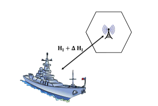
However, due to oscillatory motion of the ship, because of sea/ocean waves even if the ship is docked at harbor, the interference channel between the radar and the communication system is perturbed. In this case, the received signal at the communication system’s receiver is
where denotes perturbation in ICSI and is modeled using Rayleigh distribution, see Section IV for details, with covariance matrix
where is the column stacking operator. This spectrum sharing scenario is shown in Figure 1.
As previously stated, spatial approach of interference mitigation is projection of radar signal onto the null space of interference channel [7]. After perturbation, in order for the spatial approach to work, the radar signal is projected onto the null space of the perturbed interference channel such that .
III Colocated MIMO Radar
In this section, we introduce preliminaries of colocated MIMO radar, having transmit and receive antennas, which transmits finite-alphabet constant-envelop BPSK waveforms designed in [8]. The radar waveform can be expressed as
where is the baseband signal from the transmit element, is the carrier angular frequency, , with being the observation time. Then the received signal, from a single point target at an angle , is
where is additive white Gaussian noise, , denoting the sum of propagation delays between the target and the transmit element and the receive element, respectively; and represents the complex path loss including the propagation loss and the reflection coefficient; is the transmit steering matrix defined as
is the receive steering matrix defined as
and is the transmit-receive steering matrix defined as
Our performance metric for the MIMO radar’s performance is the maximum likelihood (ML) estimate of the target’s angle of arrival, which is expressed as, as in [9],
| (1) |
where
where is the propagation delay between the target and the reference point, and is the Doppler frequency shift as defined in Table 2 [1].
IV Physical Modeling Of The Perturbed Interference Channel
In this paper, the cause of perturbation in ICSI is due to the motion of the maritime radar, mounted on ship. This motion is induced by sea/ocean waves. So, in order to statistically describe the perturbation we look at the statistics of the wave height. The probability density function (pdf) of the wave height is given by the Rayleigh distribution as, as in [10],
where is the root-mean-square (rms) wave height defined as
where corresponds to the number of observed waves and the wave has height . Thus, can be computed by observing wave heights. We choose Rayleigh pdf for the wave height distribution as it gives a very good estimate of the wave properties for various nearshore conditions.
V Impact of The Perturbed Interference Channel on the NSP Algorithm
The projection of the radar signals onto the null space of the interference channel via a projection algorithm was proposed in [1] for a stationary interference channel. However, due to the motion of the ship, the interference channel gets perturbed and can be written as
For the NSP algorithm, the null space of the perturbed interference channel can be calculated from the singular value decomposition (SVD) theorem as
where is the perturbed complex unitary matrix, is the diagonal matrix of the perturbed singular values, and is the perturbed complex unitary matrix and its columns corresponding to the vanishing singular values span the null space of . This is denoted by . We project the radar signal onto the null space of the perturbed interference-channel using the projection algorithm, as in [1],
The radar waveform projected onto the null space of can be written as
| (2) |
By inserting the projected signal, equation (2) in equation (1), we get the ML estimate of the target’s angle of arrival for the NSP projected radar waveform as
| (3) |
VI Simulation Results
In this section, we simulate the impact of time varying interference channel on MIMO radar-communication system spectrum-sharing scenario. The interference channel is modeled to have a Rayleigh distribution. The elements of the error channel are modeled as Rayleigh distribution, as it describes the pdf of the height of the waves, with taking values 1, 2, 3, and 4, indicating perturbation in the channel coefficients. The ML results are based on the average of 10,000 independent trials. The simulation parameters used are listed in Table 2 [1].
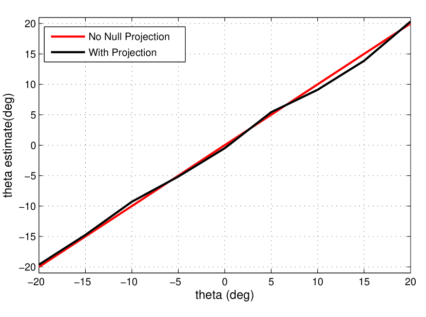

The ML estimate of the target’s angle of arrival is calculated by equations (1) and (3) for the original radar waveform and the NSP radar waveform on the perturbed interference-channel, respectively. The impact of the NSP of the radar waveform, on the perturbed interference-channel, can be studied by the ML estimation error of the angle of arrival. First, in Figure 2, we compare the original and the estimated angles using the ML estimation for the original radar waveform and the NSP waveform onto the un-perturbed interference channel. It is important to note that the NSP waveform doesn’t degrade the ML estimates or radar performance. This endorses the claims of [1] that the NSP for spectrum-sharing is a viable approach for MIMO radars. Second, we analyze the effect of the perturbation on the NSP algorithm. In Figure 3, we compare the original and the estimated angles for various magnitudes of the perturbation in the channel coefficients. It is important to note that due to the perturbation of the interference-channel the degradation in the performance of the NSP waveform is significant. The degradation also depends on the magnitude of the perturbation. It is evident that as the perturbation in the channel coefficients increases the performance of the ML, for the NSP waveform, degrades significantly. Thus, perturbation in the interference channel can have a detrimental effect on the radar performance, in a spectrum-sharing setting, when NSP approaches are used. This can be avoided by having a frequent exchange of the ICSI between radars and communication systems.
VII Conclusion
In future, federal radar spectrum will be shared with commercial operators. In this paper, we explore the spectrum-sharing scenario when the interference channel between a radar and a communication system is subject to variations due to the oscillatory motion of ship. We study the effect of perturbation, in the interference channel, when the NSP approach of spectrum sharing is used. The NSP algorithm does not degrade the radar performance when complete ICSI is available, however, when the interference channel is perturbed, by the waves, the radar’s performance is degraded. The magnitude of the degradation depends upon the magnitude of the perturbation in the channel coefficients, which is due to the height of the waves. The radar performance, in such a scenario, can be improved by having frequent updates of the ICSI.
VIII Future Work
In this paper, we considered only a single communication system sharing spectrum with a radar. However, we are looking into extending this work to multi-cell communication system [7] and studying target detection performance of spectrum sharing MIMO radars [11]. Moreover, instead of using orthogonal waveforms, MIMO radar waveforms with spectrum sharing constraints can be designed which can mitigate radar interference to communication systems [12, 13]. We are also working on various algorithms that exploit the NSP, at radar, and resource allocation along the lines of [14, 15, 16, 17, 18, 19, 20], at communication system, to mitigate interference in a radar-communication system spectrum-sharing scenario.
References
- [1] S. Sodagari, A. Khawar, T. C. Clancy, and R. McGwier, “A projection based approach for radar and telecommunication systems coexistence,” in IEEE Global Communications Conference (GLOBECOM), 2012.
- [2] The President s Council of Advisors on Science and Technology (PCAST), “Realizing the full potential of government-held spectrum to spur economic growth.” Online, July 2012.
- [3] National Telecommunications and Information Administration (NTIA), “An assessment of the near-term viability of accommodating wireless broadband systems in the 1675-1710 MHz, 1755-1780 MHz, 3500-3650 MHz, 4200-4220 MHz, and 4380-4400 MHz bands (Fast Track Report).” Online, October 2010.
- [4] A. Khawar, A. Abdel-Hadi, and T. C. Clancy, “A mathematical analysis of LTE interference on the performance of S-band military radar systems,” in 13th Annual Wireless Telecommunications Symposium (WTS), (Washington, DC, USA), Apr. 2014.
- [5] H. Yi, “Nullspace-based secondary joint transceiver scheme for cognitive radio MIMO networks using second-order statistics,” in IEEE International Communications Conference (ICC), 2010.
- [6] A. Khawar, J. Mahal, A. Abdelhadi, and T. C. Clancy, “Channel modeling between seaborne MIMO radar and MIMO cellular system,” under submission.
- [7] A. Khawar, A. Abdel-Hadi, and T. C. Clancy, “Spectrum sharing between S-band radar and LTE cellular system: A spatial approach,” in 2014 IEEE International Symposium on Dynamic Spectrum Access Networks: SSPARC Workshop (IEEE DySPAN 2014 - SSPARC Workshop), (McLean, USA), Apr. 2014.
- [8] A. Khawar, A. Abdel-Hadi, T. C. Clancy, and R. McGwier, “Beampattern analysis for MIMO radar and telecommunication system coexistence,” in IEEE International Conference on Computing, Networking and Communications, Signal Processing for Communications Symposium (ICNC’14 - SPC), 2014.
- [9] J. Li and P. Stoica, MIMO Radar Signal Processing. Wiley-IEEE Press, 2008.
- [10] M. S. Longuet-Higgins, “On the statistical distribution of the heights of sea waves,” Journal of Marine Research, vol. 11, no. 3, pp. 245–266, 1952.
- [11] A. Khawar, A. Abdelhadi, and T. C. Clancy, “Target detection performance of spectrum sharing MIMO radars,” arXiv:1408.0540.
- [12] A. Khawar, A. Abdel-Hadi, and T. C. Clancy, “MIMO radar waveform design for coexistence with cellular systems,” in IEEE International Symposium on Dynamic Spectrum Access Networks: SSPARC Workshop (IEEE DySPAN 2014 - SSPARC Workshop), (McLean, USA), Apr. 2014.
- [13] A. Khawar, A. Abdelhadi, and T. C. Clancy, “QPSK waveform for MIMO radar with spectrum sharing constraints,” arXiv:1407.8510.
- [14] A. Abdel-Hadi and C. Clancy, “A utility proportional fairness approach for resource allocation in 4G-LTE,” in IEEE International Conference on Computing, Networking and Communications: Computing, Networking and Communications Symposium (ICNC’14 - CNC), 2014.
- [15] A. Abdel-Hadi and C. Clancy, “An optimal resource allocation with joint carrier aggregation in 4G-LTE,” submission.
- [16] A. Abdelhadi, A. Khawar, and T. C. Clancy, “Optimal downlink power allocation in cellular networks,” arXiv:1405.6440.
- [17] H. Shajaiah, A. Abdel-Hadi, and C. Clancy, “Utility proportional fairness resource allocation with carrier aggregation in 4G-LTE,” in IEEE Military Communications Conference (MILCOM), 2013.
- [18] H. Shajaiah, A. Abdel-Hadi, and C. Clancy, “Spectrum sharing between public safety and commercial users in 4G-LTE,” in IEEE International Conference on Computing, Networking and Communications (ICNC), 2014.
- [19] H. Shajaiah, A. Khawar, A. Abdel-Hadi, and T. C. Clancy, “Resource allocation with carrier aggregation in LTE Advanced cellular system sharing spectrum with S-band radar,” in IEEE International Symposium on Dynamic Spectrum Access Networks: SSPARC Workshop (IEEE DySPAN 2014 - SSPARC Workshop), (McLean, USA), Apr. 2014.
- [20] M. Ghorbanzadeh, A. Abdelhadi, and T. C. Clancy, “A utility proportional fairness resource allocation in spectrally radar-coexistent cellular networks,” in IEEE Military Communications Conference (MILCOM), October 2014.