Interferometric measurement of the current-phase relationship of a superfluid weak link
Abstract
Weak connections between superconductors or superfluids can differ from classical links due to quantum coherence, which allows flow without resistance. Transport properties through such weak links can be described with a single function, the current-phase relationship, which serves as the quantum analog of the current-voltage relationship. Here, we present a technique for inteferometrically measuring the current-phase relationship of superfluid weak links. We interferometrically measure the phase gradient around a ring-shaped superfluid Bose-Einstein condensate (BEC) containing a rotating weak link, allowing us to identify the current flowing around the ring. While our BEC weak link operates in the hydrodynamic regime, this technique can be extended to all types of weak links (including tunnel junctions) in any phase-coherent quantum gas. Moreover, it can also measure the current-phase relationships of excitations. Such measurements may open new avenues of research in quantum transport.
A variety of quantum phenomena, such as Josephson effects Josephson (1964) and quantum interference Jaklevic et al. (1964); Sato and Packard (2012), can be observed by weakly connecting two superconductors or superfluids. Such a weak connection can be, for example, a narrow channel or a potential barrier that allows for quantum tunneling. For any weak link, there is a relationship between the current and the phase difference between the two superconductors or superfluids. This current-phase relationship is essential for understanding quantum transport through the weak link Likharev (1979). In superconductors, the current-phase relationship of weak links is measured routinely, and such measurements can indicate the presence of exotic quantum states, such as Majorana fermions Fu and Kane (2009); Sochnikov et al. (2013) or oscillations in the order parameter Frolov et al. (2004). In superfluid liquid helium, this current-phase relationship has been measured, but only indirectly Hoskinson et al. (2005). In degenerate atomic gases, the current-phase relationship has not yet been measured (although many of the effects associated with weak links, e.g., Josephson effects Albiez et al. (2005); Levy et al. (2007), have been observed). Here, we interferometrically measure the phase around a ring-shaped superfluid Bose-Einstein condensate (BEC). We use this technique to determine both the magnitude and sign of persistent currents in the ring. In the presence of a rotating constriction that acts as a weak link, we show how to measure its current-phase relationship.
In a superfluid, the velocity is related to the gradient of the phase of the macroscopic wavefunction by , where is Planck’s constant divided by and is the mass of an atom. Ignoring the transverse degrees of freedom, the number current is then , where is the equivalent 1D density of the fluid along the direction of flow. In a weak link, the superfluid density will vary as a function of position and velocity 111A non-linear current-phase relationship arises only if in the weak link depends on the velocity in the weak link., resulting in a potentially complicated current-phase relationship Watanabe et al. (2009). For example, in an idealized Josephson junction, which is typically realized with a tunnel barrier, the phase drop across the weak link is related to the current through , where is its critical current. Because the ideal Josephson junction can be hard to achieve, the current-phase relationships of experimentally realizable weak links can exhibit higher order harmonics or become multivalued Baratoff et al. (1970); Piazza et al. (2010); Deaver Jr. and Pierce (1972).
In the present case, we generate a constriction that acts as a weak link in that its critical velocity is much less than that of the rest of the system Likharev (1979). However, our weak link is large compared to healing length of the BEC, leading to a linear current-phase relationship similar to that of a bulk superfluid. Previous works Albiez et al. (2005); Levy et al. (2007); Ryu et al. (2013) used weak links that operated in the tunneling regime; however, none of these measured the current-phase relationship.
Weak links have enabled manipulation of ring-shaped BECs, by both controlling a persistent current Ramanathan et al. (2011); Moulder et al. (2012); Wright et al. (2013); Ryu et al. (2014); Eckel et al. (2014) and inducing flow between reservoirs Ryu et al. (2013); Jendrzejewski et al. (2014). Because the wavefunction must be single valued, the integral of around any closed path must be a multiple of . In particular, for a ring with mean radius , this leads to the constraint , where is the azimuthal angle and the integer is a topological invariant known as the winding number. Transitions between these quantized states can occur when a weak link stirs the superfluid at a critical rotation rate Wright et al. (2013); Eckel et al. (2014). In previous experiments with ring-shaped condensates, the detection method used could only measure the magnitude of resulting winding number . Here, we use an interference technique to measure the phase and therefore the current flow around a ring-shaped BEC. We demonstrate that when the rotating weak link is present, there is already a current around the ring even if . This implies that while the winding number is quantized, neither the average current nor the total angular momentum of the BEC are quantized.
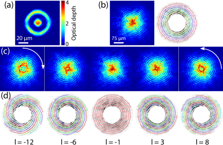
To measure the phase around the ring, we use two BECs of 23Na atoms held in an optical dipole trap, as shown in Fig 1(a). One is shaped like a disk and serves as a phase reference. The other is a concentric ring, which can sustain a persistent current. To detect the phase of the wavefunction and thus the current in the condensate, we interfere the two separate condensates, which can be accomplished after time-of-flight (TOF) expansion. In fact, such interference experiments provided the first conclusive proof that a BEC is a single, phase-coherent object Andrews et al. (1997). Later experiments used similar interference techniques to detect quantized vortices Inouye et al. (2001), to investigate the coherence properties of a superfluid Fermi gas Kohstall et al. (2011), and to study the physics of both two dimensional Hadzibabic et al. (2006) and one-dimensional Bose gases Hofferberth et al. (2007). A method similar to that presented here has been independently developed to investigate the supercurrent generated by a rapid quench through the BEC transition Corman et al. (2014).
Measuring the interference of our BECs after TOF expansion yields a measurement of , where is the wavefunction of the disk and is the wavefunction of the ring. The first term produces no fringes as the disk expands. The terms that are of most interest here contain the ring and the disk, , and they interfere once and expand such that they overlap. The last term, , can also produce an interference pattern once the ring has expanded further, such that its characteristic width becomes comparable to . At this point, the opposite sides of the ring can interfere with each other.
For simplicity, let us first consider the interference pattern when there is no weak link present and both BECs are at rest before being released from the trap [Fig. 1(b)]. Without flow, the phase is independent of angle in both the disk and ring. The interference term results in concentric circles. The radial position of these azimuthal interference fringes depends on the relative phases between the two condensates; the radial separation between fringes corresponds to a phase difference of . The interference term produces similar concentric circles, but with a contrast that is below our detection threshold Murray et al. (2013); Ryu et al. (2014).
If there is no weak link present but there is a non-zero winding number in the ring, the resulting interference patterns are modified. In this case, the phase of the ring wavefunction will be given by , assuming the ring is sufficiently smooth that both and are independent of the azimuthal angle . Such a phase profile represents a quantized persistent current: the current takes on discrete values , where and . As shown in Refs. Murray et al. (2013); Ryu et al. (2014), the interference is modified in this case: a hole with quantized size appears at long times. Previous experiments Wright et al. (2013); Beattie et al. (2013); Eckel et al. (2014) demonstrated quantized persistent currents in a ring by releasing the BEC from a ring-shaped trap (without another BEC present) and observing the size of the resulting hole. While this method determines the magnitude of the current, it does not determine the direction.
In addition to modifying the term, a persistent current also modifies the interference term , turning the concentric circles into spirals when [Fig. 1(c)]. (The circular structures observed at the center of the clouds for large winding numbers are associated with the emergence of the quantized hole described by .) The combination of the initial azimuthal velocity of the ring atoms and the expansion of the clouds creates spirals in the interference pattern. One can use such spirals to measure the accumulated phase around the ring by tracking a maximum (or a minimum) of an interference fringe from to . The net radial fringe displacement divided by the spacing between fringes yields . Because in the present case, this procedure is equivalent to counting the number of spiral arms, which determines the magnitude of , and noting their chirality, which determines its sign.
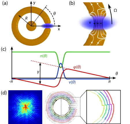
Adding the weak link modifies the interference pattern beyond the spirals described above. The weak link, as shown in Fig. 2(a)–(b), is a density-depleted region in the ring. Once the cloud is released, atoms from either side of the density-depleted weak link expand toward each other and interfere, causing additional interference fringes to appear in the radial direction, as shown in Fig. 2(d). Just as in the case where there was no weak link, we can still measure by tracking the azimuthal interference fringes around the ring, excluding the weak link region. To measure their radial displacement after going from to , one must extrapolate those fringes back through the weak link region. Dividing the size of the extrapolated radial displacement of a single fringe by the spacing between the fringes once again yields . Here, is not necessarily a multiple of . This measurement of allows us to extract the current-phase relationship of the weak link, as shown below.
Before discussing the results, we first describe the experimental techniques. The ring and the disk traps are formed by the combination of two crossed lasers. A red-detuned laser shaped like a sheet creates vertical confinement, while an intensity-masked blue-detuned laser separates the ring trap from the disk trap to form the two BECs. A blue-detuned laser generates the weak link by creating a Gaussian-shaped repulsive potential of height and full-width of m (for details on the weak link, see Ref. Jendrzejewski et al. (2014)). This potential depletes the density in a small portion of the ring, as shown in Fig. 2(a). On average, a total of atoms reside in the traps. The ring BEC has a mean radius of m and annular width (twice the Thomas-Fermi radius) of m. It contains % of the atoms and has an initial chemical potential kHz. The central disk contains % of the atoms and has a Thomas-Fermi radius of m. While the disk is approximately hard-walled, the ring is closer to harmonic with a measured radial trapping frequency of Hz. The distance between the inner radius of the ring and the disk is m.
To prepare the system in a well defined quantized persistent current state with a chosen , we stir our weak link at a corresponding . Such stirring lasts for 1 s, during which the rotation rate of the weak link is constant but the strength of the weak link potential ramps on linearly in 300 ms, holds constant for 400 ms, and ramps off in another 300 ms. To measure the resulting , we hold the BECs for an additional 100 ms, then release them, and lastly, image the interference pattern after 15 ms TOF expansion. This procedure produced the data shown in Fig. 1(b)–(c).
We extend these results by measuring in the presence of a weak link as a function of , the rotation rate , and the initial winding number . First, we stir to set the initial winding number or , as described above. To get the highest fidelity for setting (95(2) %), we empirically find that and Hz or zero, depending on which winding number state we wish to initialize. Second, we stir for 1 s at a new and . During the first 300 ms of this second stage of stirring, the weak link potential ramps from zero to the chosen , and afterwards remains constant. We adjust the starting position such that the weak link is at at the end of this second step. At this point, the trap and weak link potential turn off, which releases the cloud. After 17 ms TOF (for slightly better resolution), we again image the cloud.
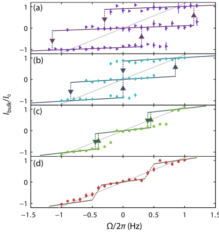
The above procedures result in a measurement of the phase accumulated around the ring, , which is related to the current around the bulk of the ring through . We measure , normalized to , as a function of for a variety of different ; Fig. 3 shows four examples. As shown, there are discrete jumps in at specific rotations rates. At these critical rotation rates, the system experiences a phase slip which changes . These critical rotation rates are dependent on , and can be hysteretic. Fig. 3(a)–(b) show such hysteresis. The size of the hysteresis loop is consistent with previous measurements Eckel et al. (2014). In addition, we measure a non-zero, superfluid for rotation rates below the critical rotation rate, where presumably there are no excitations and .
can be understood in the following way: As the weak link rotates around the ring, it must displace superfluid from in front of its path and superfluid must fill in behind it. The number of atoms that must flow per unit time is proportional to the difference in the density in the weak link and the bulk of the ring. If the flow was only confined to the weak link and in the direction opposite of the rotation, as shown by the solid stream lines in Fig. 2(b), it would violate the condition . Thus, the atoms in the bulk of the ring must have some velocity in the same direction as the rotation (dashed flow lines) in order to cancel the phase accumulated by the atoms moving through the weak link, as shown in Fig. 2(c). This is analogous to fluxoid vs. flux quantization in superconductors Tilley and Tilley (1990): although must always be quantized, neither the current or the total angular momentum are (see Supplemental).
Initially, vs. is linear, and Fig. 4(a) shows its measured derivative as a function of . As , no atoms move, and for all . For a given rotation, increasing displaces more atoms, resulting in a larger current around the bulk of the ring. As expected, continues to increase until , at which point no atoms can move through the weak link and they all must move around the ring, i.e., . This limit corresponds to solid-body rotation; Fig. 3 shows this limit as thin gray lines. In a reference frame that rotates with the weak link, there is no flow in this limit and thus , where is the current in the weak link’s frame. The opposite limit of corresponds to (where we have taken to represent flow that is opposite the rotation).
The vs. curves of Fig. 3 can be predicted using a model based on the local density approximation (LDA) to the Gross-Pitaevksii equation (see Supplemental and Ref Watanabe et al. (2009)), but assuming a critical velocity as measured in Ref. Eckel et al. (2014). (An LDA treatment can be used because the azimuthal length of the weak link of m is larger than the healing length m.) All parameters are measured independently; none are adjustable. The predictions of this model are shown in Figs. 3 and 4(a) as the solid curves.
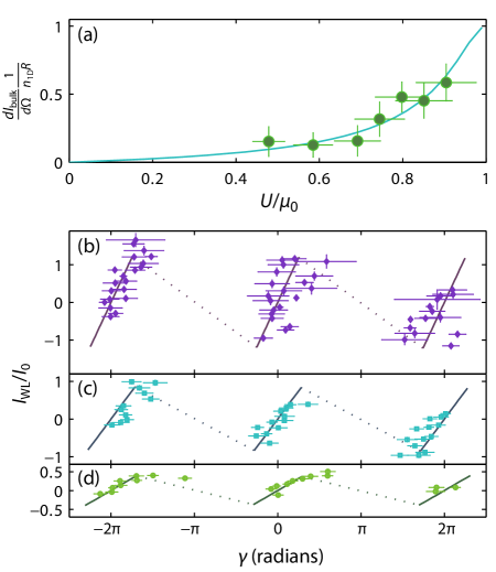
The current-phase relationship is best evaluated in the weak link’s frame, where . The phase drop across the weak link, , that corresponds to is given by [see Fig. 2(c)]. For a constant , the current-phase relationship determines how much current flows past the weak link (, measured in the weak link’s frame) and how much flows past a fixed point in the bulk of the ring (). Using these relationships, we can extract the current phase-relationship from the data in Fig. 3, the results of which are shown in Fig. 4(b)–(d).
For our BEC system, our model predicts that the current-phase relationship is roughly linear. Non-linearities caused by changes in the superfluid density with occur when the velocity through the weak link nears the speed of sound; however, because our critical velocity is lower than the speed of sound, these non-linearities are small. Thus, our weak link is far from an ideal Josephson junction. We also note that our simple model cannot predict the current-phase relationship in the region indicated by the dotted line in Fig. 4(b)–(d). (The dotted lines merely guide the eye between the predicted branches.) In this branch, we expect dissipation to play a key role in the dynamics.
Ideally, one would want to apply our method to a weak link that could be tuned from the hydrodynamic flow regime observed here to the Josephson or tunneling regime. For the ideal Josephson junction with a sinusoidal current-phase relationship, the vs. lines in Fig 3 would be curved, a signature that has yet to be observed in degenerate atomic gases. To obtain such a signature, one would need a potential barrier whose width is comparable to the healing length of the condensate to suppress hydrodynamic flow but allow quantum mechanical tunneling.
In conclusion, we have demonstrated a technique for measuring the current-phase relationship of a weak link in a dilute-gas superfluid BEC. We demonstrate that a rotating weak link always generates a superfluid current in the bulk of the ring, even when the rotation rate is less than any critical velocity in the system. The magnitude of that current is determined by the current-phase relationship. Our new method will allow for better characterization of weak links and, in the case of a tunnel junction, should provide the signature of the existence of idealized Josephson junctions in BEC systems. In addition, measurement of the current-phase relationship enables prediction of the hysteretic energy landscape of our system Eckel et al. (2014), which, like the energy landscape of a flux qubit, should be quantized Clarke and Wilhelm (2008). More broadly, it is possible that this method can be extended to measure the current-phase relationships of various excitations, such as solitonic-vortices Ku et al. (2014). Lastly, this powerful tool may prove important for studying transport in other, exotic forms of quantum matter, such as unitary Fermi gases Yefsah et al. (2013), Tonks-Giradeau gases Paredes et al. (2004); Kinoshita et al. (2004), and quasi-2D condensates near the BKT transition Hadzibabic et al. (2006).
Acknowledgements.
The authors thank J.G. Lee for technical assistance, M. Edwards, E. Tiesinga, R. Mathew, and W. T. Hill III for useful discussions. We thank W.D. Phillips for an extremely thorough reading of the manuscript. This work was partially supported by ONR, the ARO atomtronics MURI, and the NSF through the PFC at the JQI. S. Eckel is supported by a National Research Council postdoctoral fellowship.References
- Josephson (1964) B. Josephson, “Coupled Superconductors,” Rev. Mod. Phys. 36, 216–220 (1964).
- Jaklevic et al. (1964) RC Jaklevic, John Lambe, AH Silver, and JE Mercereau, “Quantum Interference Effects in Josephson Tunneling,” Phys. Rev. Lett. 12, 159–160 (1964).
- Sato and Packard (2012) Y Sato and R E Packard, “Superfluid helium quantum interference devices: physics and applications.” Rep. Prog. Phys. 75, 016401 (2012).
- Likharev (1979) K.K. Likharev, “Superconducting weak links,” Rev. Mod. Phys. 51, 101–159 (1979).
- Fu and Kane (2009) Liang Fu and C. Kane, “Josephson current and noise at a superconductor/quantum-spin-Hall-insulator/superconductor junction,” Phys. Rev. B 79, 161408 (2009).
- Sochnikov et al. (2013) Ilya Sochnikov, Andrew J Bestwick, James R Williams, Thomas M Lippman, Ian R Fisher, David Goldhaber-Gordon, John R Kirtley, and Kathryn A Moler, “Direct measurement of current-phase relations in superconductor/topological insulator/superconductor junctions.” Nano Lett. 13, 3086–92 (2013).
- Frolov et al. (2004) S. Frolov, D. Van Harlingen, V. Oboznov, V. Bolginov, and V. Ryazanov, “Measurement of the current-phase relation of superconductor/ferromagnet/superconductor Josephson junctions,” Phys. Rev. B 70, 144505 (2004).
- Hoskinson et al. (2005) E Hoskinson, Y Sato, I Hahn, and R E Packard, “Transition from phase slips to the Josephson effect in a superfluid 4He weak link,” Nat. Phys. 2, 23–26 (2005).
- Albiez et al. (2005) Michael Albiez, Rudolf Gati, Jonas Fölling, Stefan Hunsmann, Matteo Cristiani, and Markus K. Oberthaler, “Direct Observation of Tunneling and Nonlinear Self-Trapping in a Single Bosonic Josephson Junction,” Phys. Rev. Lett. 95, 010402 (2005).
- Levy et al. (2007) S Levy, E Lahoud, I Shomroni, and J Steinhauer, “The a.c. and d.c. Josephson effects in a Bose-Einstein condensate,” Nature 449, 579–583 (2007).
- Note (1) A non-linear current-phase relationship arises only if in the weak link depends on the velocity in the weak link.
- Watanabe et al. (2009) Gentaro Watanabe, F Dalfovo, F Piazza, L. Pitaevskii, and S Stringari, “Critical velocity of superfluid flow through single-barrier and periodic potentials,” Phys. Rev. A 80, 53602 (2009).
- Baratoff et al. (1970) Alexis Baratoff, James A Blackburn, and Brian B Schwartz, “Current-Phase Relationship in Short Superconducting Weak Leaks,” Phys. Rev. Lett. 25, 1096 (1970).
- Piazza et al. (2010) F Piazza, L A Collins, and A Smerzi, “Current-phase relation of a Bose-Einstein condensate flowing through a weak link,” Phys. Rev. A 81, 33613 (2010).
- Deaver Jr. and Pierce (1972) B S Deaver Jr. and J M Pierce, “Relaxation oscillator model for superconducting bridges,” Phys. Lett. A 38, 81–82 (1972).
- Ryu et al. (2013) C. Ryu, P. W. Blackburn, a. a. Blinova, and M. G. Boshier, “Experimental Realization of Josephson Junctions for an Atom SQUID,” Phys. Rev. Lett. 111, 205301 (2013).
- Ramanathan et al. (2011) A. Ramanathan, K. C. Wright, S. R. Muniz, M. Zelan, W. T. Hill, C. J. Lobb, K. Helmerson, W. D. Phillips, and G. K. Campbell, “Superflow in a Toroidal Bose-Einstein Condensate: An Atom Circuit with a Tunable Weak Link,” Phys. Rev. Lett. 106, 130401 (2011).
- Moulder et al. (2012) Stuart Moulder, Scott Beattie, Robert P. Smith, Naaman Tammuz, and Zoran Hadzibabic, “Quantized supercurrent decay in an annular Bose-Einstein condensate,” Phys. Rev. A 86, 013629 (2012).
- Wright et al. (2013) K. Wright, R. Blakestad, C. Lobb, W. Phillips, and G. Campbell, “Driving Phase Slips in a Superfluid Atom Circuit with a Rotating Weak Link,” Phys. Rev. Lett. 110, 25302 (2013).
- Ryu et al. (2014) C Ryu, K C Henderson, and M G Boshier, “Creation of matter wave Bessel beams and observation of quantized circulation in a Bose–Einstein condensate,” New J. Phys. 16, 013046 (2014).
- Eckel et al. (2014) Stephen Eckel, Jeffrey G. Lee, Fred Jendrzejewski, Noel Murray, Charles W. Clark, Christopher J. Lobb, William D. Phillips, Mark Edwards, and Gretchen K. Campbell, “Hysteresis in a quantized superfluid ‘atomtronic’ circuit,” Nature 506, 200–203 (2014).
- Jendrzejewski et al. (2014) F Jendrzejewski, S Eckel, N Murray, C Lanier, M Edwards, C. J. Lobb, and G. K. Campbell, “Resistive Flow in a Weakly Interacting Bose-Einstein Condensate,” Phys. Rev. Lett. 113, 045305 (2014).
- Andrews et al. (1997) M. R. Andrews, C. G. Townsend, H.-J. Miesner, D. S. Durfree, D. M. Kurn, and W. Ketterle, “Observation of Interference Between Two Bose Condensates,” Science 275, 637 (1997).
- Inouye et al. (2001) S. Inouye, S. Gupta, T. Rosenband, A. Chikkatur, A. Görlitz, T. Gustavson, A. Leanhardt, D. Pritchard, and W. Ketterle, “Observation of Vortex Phase Singularities in Bose-Einstein Condensates,” Phys. Rev. Lett. 87, 080402 (2001).
- Kohstall et al. (2011) C Kohstall, S Riedl, E R Sánchez Guajardo, L a Sidorenkov, J Hecker Denschlag, and R Grimm, “Observation of interference between two molecular Bose–Einstein condensates,” New J. Phys. 13, 065027 (2011).
- Hadzibabic et al. (2006) Zoran Hadzibabic, Peter Krüger, Marc Cheneau, Baptiste Battelier, and Jean Dalibard, “Berezinskii-Kosterlitz-Thouless crossover in a trapped atomic gas.” Nature 441, 1118–21 (2006).
- Hofferberth et al. (2007) S Hofferberth, I Lesanovsky, B Fischer, T Schumm, and J Schmiedmayer, “Non-equilibrium coherence dynamics in one-dimensional Bose gases.” Nature 449, 324–7 (2007).
- Corman et al. (2014) Laura Corman, Lauriane Chomaz, Tom Bienaimé, Rémi Desbuquois, Christof Weintenberg, Sylvain Nascimbene, Jean Dalibard, and Jérôme Beugnon, “Quench-induced supercurrents in an annular two-dimensional Bose gas,” , 1–7 (2014), arXiv:1406.4073 .
- Murray et al. (2013) Noel Murray, Michael Krygier, Mark Edwards, K. C. Wright, G. K. Campbell, and Charles W. Clark, “Probing the circulation of ring-shaped Bose-Einstein condensates,” Phys. Rev. A 88, 053615 (2013).
- Beattie et al. (2013) Scott Beattie, Stuart Moulder, Richard J. Fletcher, and Zoran Hadzibabic, “Persistent Currents in Spinor Condensates,” Phys. Rev. Lett. 110, 025301 (2013).
- Tilley and Tilley (1990) David R Tilley and John Tilley, Superfluidity and Superconductivity, 3rd ed., edited by Douglas F Brewer (Adam Hilger, 1990).
- Clarke and Wilhelm (2008) John Clarke and Frank K Wilhelm, “Superconducting quantum bits,” Nature 453, 1031–1043 (2008).
- Ku et al. (2014) Mark J. H. Ku, Wenjie Ji, Biswaroop Mukherjee, Elmer Guardado-Sanchez, Lawrence W. Cheuk, Tarik Yefsah, and Martin W. Zwierlein, “Motion of a Solitonic Vortex in the BEC-BCS Crossover,” Phys. Rev. Lett. 113, 065301 (2014).
- Yefsah et al. (2013) Tarik Yefsah, Ariel T Sommer, Mark J H Ku, Lawrence W Cheuk, Wenjie Ji, Waseem S Bakr, and Martin W Zwierlein, “Heavy solitons in a fermionic superfluid,” Nature 499, 426–30 (2013).
- Paredes et al. (2004) Belén Paredes, Artur Widera, Valentin Murg, Olaf Mandel, Simon Fölling, Ignacio Cirac, Gora V Shlyapnikov, Theodor W Hänsch, and Immanuel Bloch, “Tonks-Girardeau gas of ultracold atoms in an optical lattice.” Nature 429, 277–81 (2004).
- Kinoshita et al. (2004) Toshiya Kinoshita, Trevor Wenger, and David S Weiss, “Observation of a one-dimensional Tonks-Girardeau gas,” Science 305, 1125–8 (2004).