Open Cell Conducting Foams for High Synchrotron Radiation Beam Liners
Abstract
The possible use of open-cell conductive foams in high synchrotron radiation particle accelerator beam liners is considered. Available materials and modeling tools are reviewed, potential pros and cons are discussed, and preliminary conclusions are drawn.
pacs:
29.20.db, 41.60.Ap, 88.40.fhI INTRODUCTION
Molecular gas desorption from the beam-pipe wall
due to synchrotron radiation
should be properly taken into account
in the design of high energy particle accelerators and storage rings.
This has been a major (solved) challenge for the Large Hadron Collider;
will be even more critical for the HE-LHC,
in view of its higher level of synchrotron radiation HELHC ,
and will be a crucial issue for the successful operation
of the proposed electron-positron Higgs factories epH .
In the CERN Large Hadron Collider LHC a copper-coated stainless-steel beam pipe (the liner)
is kept at by active Helium cooling, and effectively handles
the heat load represented by synchrotron radiation,
photoelectrons, and image-charge losses.
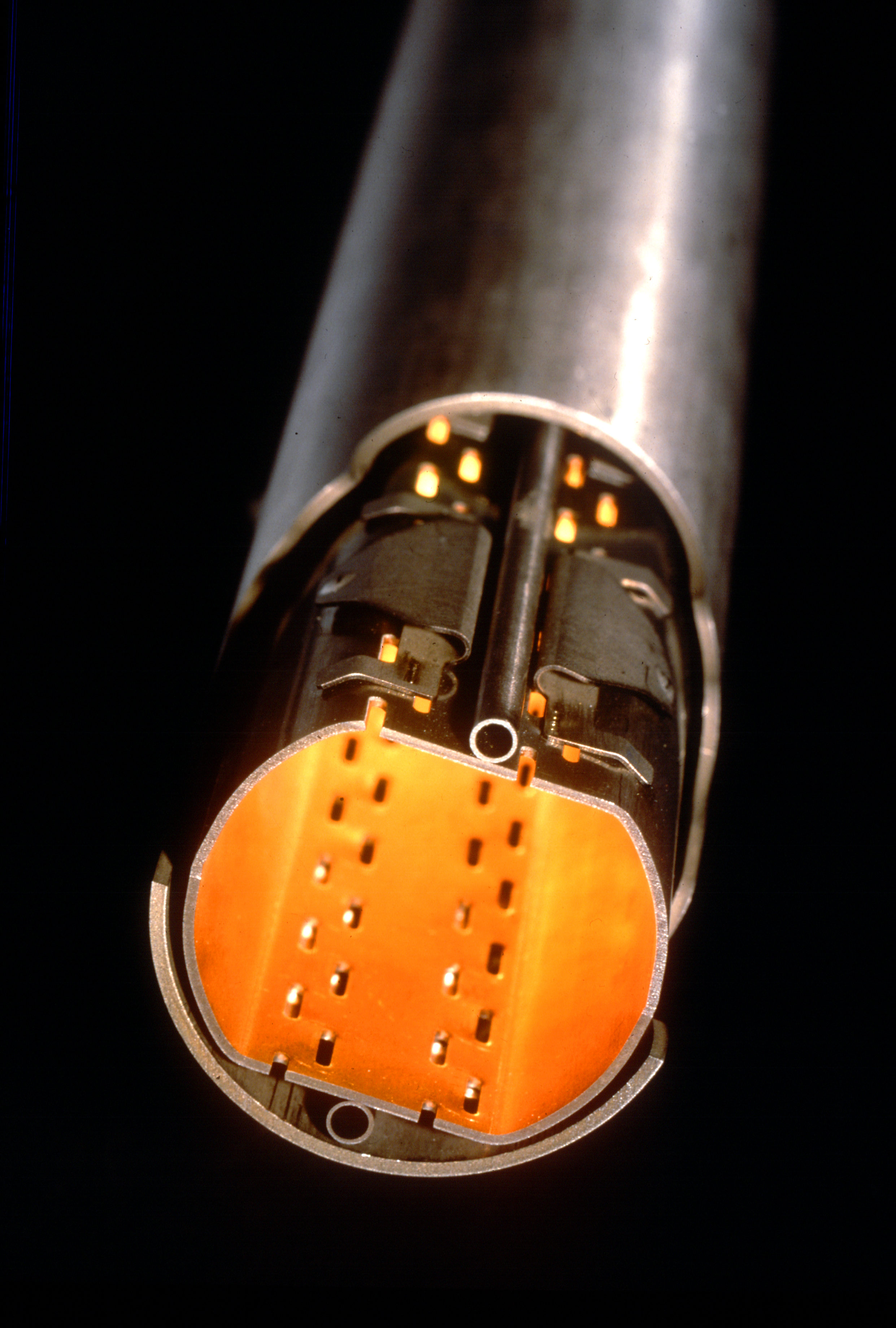
A large number ( ) of tiny slots are drilled in the liner wall (see Figure 1)
in order to maintain the desorbed gas densities below a critical level
(e.g., for )
by allowing desorbed gas to be continuously cryopumped toward the
stainless steel cold bore (co-axial to the liner) of the superconducting magnets,
which is kept at by superfluid Helium.
Above such critical density levels, nuclear scattering in the residual gas would
limit the beam luminositity lifetime, eventually originate
high energy protons which may cause thermal runaway,
and ultimately cause quenching of the superconducting magnets.
The size, geometry, placement and density of the pumping slots
affect the beam dynamics and stability in a way which is
synthetically described by the longitudinal and transverse
beam coupling impedances Zotter .
The slot geometry and placement should be further chosen
so as to minimize the effect of trapped (cut-off) modes,
and to prevent the possible coherent buildup of radiation
in the TEM waveguide limited by (the outer surface of) the pipe and the cold bore Heifets .
Open-cell conducting foams could be interesting candidate materials
to help fulfilling the above general requirements in
beam liner design.
In addition, the surface roughness of conducting foams may help reducing
the effective secondary-emission yield (SEY) roughSEY ,
thus alleviating the electron-cloud build-up phenomenon ecloud ,
and related instabilities ecloud2 .
In this paper we present a brief review of open cell conducting foams properties
and modeling tools,
and discuss at a very preliminary level the pros and cons of their possible use
in high synchrotron radiation accelerator beam liners.
II OPEN CELL METAL FOAMS
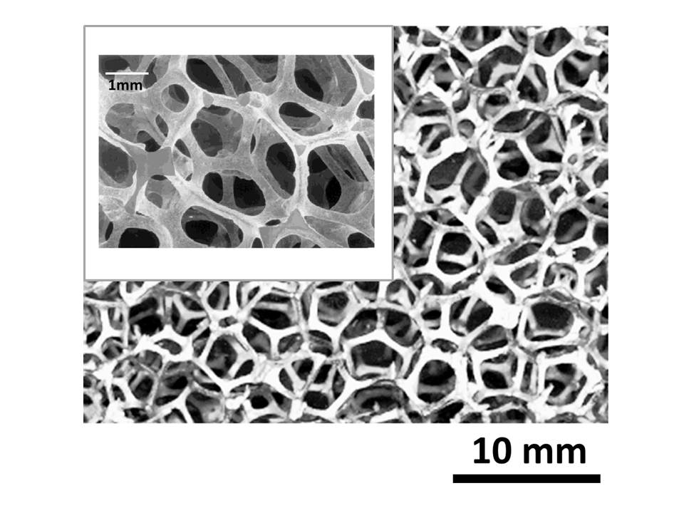
Open cell metal foams (OCMF) can be produced by vapor (or electro) deposition of metal on an open cell polymer template, followed by polymer burn-off, and a final sintering step to densify the ligaments. Alternatively, they can be synthetised by infiltration/casting of molten metal into a solid mould, consisting of packed (non-permeable) templates of the foam pores, followed by burn-out and removal of the mould rev1 . Both processes result into highly gas-permeable reticular materials, where only a 3D web of thin conducting ligaments survives. The typical structure of OCMFs is displayed in Figure 2.
The key structural parameters of OCMF are the ”pore” size, and the porosity (volume fraction of pores). Pore sizes in the range from to and porosities in the range 0.7 - 0.99 are typical. These two parameters determine the gas-permeability of the material, and, together with the electrical properties of the metal matrix, its electrical characteristics. OCMF have remarkable structural properties (low density and weight, high (tensile and shear)-strength to weight ratio, nearly isotropic load response, low coefficient of thermal expansion), as summarized in Table I, which qualified them among the most interesting new materials for aerospace applications.
| Units | Al | Cu | |
|---|---|---|---|
| Compressive Strength | |||
| Tensile Strength | |||
| Shear Strength | |||
| Elastic Modulus (Compr.) | |||
| Elastic Modulus (Tens.) | |||
| Shear Modulus | |||
| Specific Heat | |||
| Bulk Thermal Cond. | |||
| Thermal Expansion Coeff. | |||
| Bulk Resistivity | |||
| Melting Point |
.
Aluminum and Copper OCMF are presently available off-the-shelf
from several Manufacturers worldwide, and are relatively cheap.
They can be coated, with Silver, Titanium or Platinum,
for special purpose applications.
Steel and Brass foams, as well as Silver, Nickel, Cobalt, Rhodium, Titanium or Beryllium foams
have been also produced.
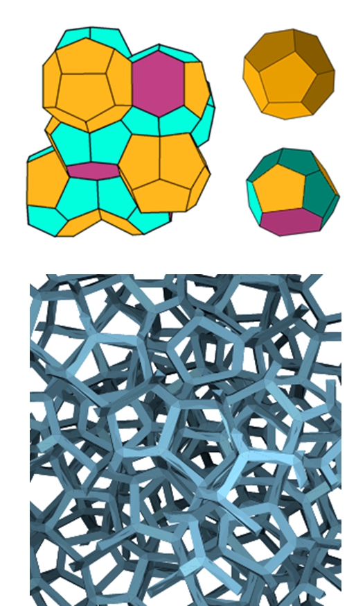
The Weaire-Phelan (WP) space-filling honeycombs are credited
to provide the natural
(i.e., Plateau’s minimal surface principle compliant)
model of OCMF with equal-sized
(but possibly unequal-shaped) pores WeaPh .
The WP unit cell consists of a certain arrangement of (irregular)
polyhedra, namely two pentagonal-face dodecahedra (with tetrahedral symmetry ) ,
and six tetrakaidecahedra (with antiprysmatic symmetry ) featuring
two hexagonal and twelve pentagonal faces WeaPh .
A computer generated WP honeycomb is displayed in Figure 3, and
its visual similarity to Figure 2 is apparent.
A powerful open-source cross-platform software project for 3D morphological
characterization and modeling of cellular materials, including OCMF,
is under development iMorph .
II.1 Electrical Properties of Conducting Foams
Electromagnetic modeling of OCMFs has been thoroughly investigated during the last decade.
A numerical approach based on Weiland finite integration technique
(FIT, Weiland ) has been proposed by Zhang et al. Zhang to compute
the (frequency, thickness and angle of incidence dependent) reflection coefficient
of foam, and optimize its design.
The main limitation of Zhang’s analysis is in the use of a simple body-centered-cubic
unit-cell foam model, for easiest numerical implementation.
The FIT scheme, however may accommodate more complicated and realistic
foam-cell geometries, including in principle the WP one.
In the quasi-static limit ,
the conductivity of OCMFs can be computed using effective medium theory
(EMT), for which several formulations exist (see, e.g., Rev1 ,RevN for a review).
These include:
i) the self-consistent approach effective_med , credited to Bruggemann,
where inclusions are thought of as being embedded in the (actual) effective medium;
ii) the differential scheme, whereby inhomogeneities are incrementally added to the composite333
In this approach, the total concentration of inhomogeneities does not coincide with the volume fraction ,
because at each step new inclusions may be placed where old inclusions have already been set.,
until the final concentration is reached, so that at each step the inclusions do not interact
and do not modify the field computed at the previous step differential ;
iii) the effective-field methods, whereby interaction among the inclusions is described in terms of an effective field
acting on each inclusion, accounting for the presence of the others.
Two main versions of this method exist, credited to Mori-Tanaka MorTan and Levin-Kanaun LevKan ,
differing in the way the effective field is computed
(average over the matrix only, or average over the matrix and the inclusions, respectively).
The self-consistent approach yields
| (1) |
where is the bulk metal conductivity, is the porosity (volume fraction of the vacuum bubbles), and is a morphology-dependent factor. The differential approach yields
| (2) |
while the Mori-Tanaka/Levin-Kanaun approaches yield
| (3) |
All equations (1)-(3) merge, as expected, in the limit. The above models are synthetically compared to measured values of the static conductivity in Figure 4, for Aluminum foams.
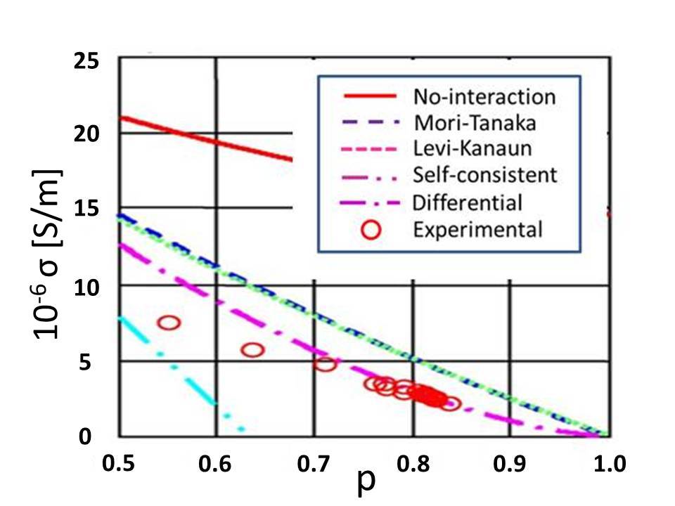
For Aluminum foams, all these models predict larger conductivity then observed in measurements444
It should be noted that open and closed cell metal foams behave similarly in terms of electrical conductivity,
while being markedly different as regards thermal conductivity, due to the different role of convective flow..
This has been attributed to significant oxide formation on the solid web Clyne .
Equation (2) agrees in form with predictions
based on percolation theory perco - although strictly speaking
there is no threshold here beyond which the conducting component disconnects.
Measurements of the microwave electromagnetic shielding efficiency of OCMF panels
Monti indicate that a simple Drude model
| (4) |
provides a good description of the frequency-dependent conductance of metallic foams. Typically, the relevant plasma and collision frequencies, and are of the order of a few tens of GHz and a few tens of KHz, respectively. These are notably much smaller555 In the light of the well known formula this can be explained as due to a reduction of the electron density , roughly by a factor , being the porosity and a parallel (large) increase of the effective electron mass. Pendry et al. have shown that the effective mass of an electron in a thin-conducting-wire lattice or web is essentially set by its electromagnetic momentum, yielding Pendry where and are the typical conducting-ligament and pore diameters, respectively, and . than their solid metal counterparts (typically in the and range, respectively Ordal ).
II.1.1 OCMF Impedance and Skin Depth
Throughout a typical beam current frequency spectrum, OCMF and bulk metals behave quite differently666 The typical power spectrum of a bunched beam in a ring collider consists of lines at integer multiples of , being the bunch spacing, with an envelope approximately . In the LHC the dB bandwidth is GHz, roughly times the circulation frequency , and times the cut-off frequency of the lowest waveguide mode of the beam pipe Day .. In bulk metals , so that the characteristic impedance and (complex) propagation constant can be written
| (5) |
and being the vacuum characteristic impedance and propagation constant, respectively. It is seen that in metallic conductors, both and are .
In OCMFs, on the other hand, throughout the beam current spectrum,
so that the material exhibits a plasmonic behavior. The OCMF wall (characteristic) impedance and (complex) propagation constant are thus given
(to lowest order in the small quantities and ) by
| (6) |
Hence, the OCMF characteristic resistance and skin depth are both frequency independent, and, e.g., for the case of high-grade ( at ) Copper foam with , both fairly small:
| (7) |
The OCMF characteristic reactance
| (8) |
on the other hand, is large compared to that of bulk metal,
and grows linearly with .
For the case, e.g., of high-grade Copper foam with ,
at .
II.2 Superconducting Foams
At the operating temperature of the LHC liner (),
both Aluminum and Copper exhibit a fairly large conductivity
(),
but neither of them is superconducting.
Superconducting OCMFs have been discussed in SC_foams .
Foamed ceramic superconductors (in particular, YBCOs)
with critical temperature well above (HTS),
have also been already manufactured HTS_foams .
These materials may likely exhibit a very low SEY.
Besides being technologically appealing, HTS foams
are conceptually interesting materials,
where a percolating electric current co-exists
with a percolating magnetic flux Bartolome .
A substantial body of experimental results
on the electrical properties of thin-film HTS is available HTS_EM_props ,
and these are reasonably well accounted for 2fluid_HTS
by a simple two-fluid Drude model 2fluid_Drude .
However, the electrical properties of foamed HTS
have been investigated sofar,
to the best of our knowledge
mostly at very low frequencies HTS_foam_cond .
III METAL FOAM vs PERFORATED METAL PATCHED PIPES
In this section we shall attempt to draw a comparison between beam pipes using perforated-metal patches for outgassing vs pipes using OCMF patches, in terms of the relevant vacuum and beam-coupling impedance features .
III.1 Vacuum Issues
The vacuum dynamics for each molecular species which may be desorbed from the wall by synchrotron radiation can be described by the following set of (coupled) rate equations Grobner :
| (9) |
Here and are the
volume and surface densities of desorbed particles, respectively,
and and represent the volume and wall-area of the liner
per unit length, respectively.
The first term on the r.h.s. of the first rate equation represents the
number of molecules desorbed by synchrotron radiation per unit length
and time, and is given by
| (10) |
where is the desorption yield (number of desorbed molecules per incident photon) and is the specific photon flux (number of photons hitting the wall per unit length and time). The second term represents the number of molecules which are removed per unit time and unit length by either sticking to the wall, or escaping through the pumping holes/slots. The coefficient in (9) can be accordingly written
| (11) |
where is the average molecular speed, being the molecular mass, the Boltzmann constant and the absolute temperature, is the average number of collisions of a single molecule per unit time and unit wall surface, is the sticking probability, and is the escape probability. The third term accounts for thermal or radiation induced re-cycling of molecules sticking at the walls. The coefficient in (9) can be accordingly written
| (12) |
Here the first term accounts for radiation induced recycling,
described by the coefficient ,
while the second term describes thermally-activated recycling,
being a typical molecular vibrational frequency,
and a typical activation energy.
The term appears
with reversed sign on the r.h.s. of the second rate equation,
where it represents the number of molecules de-sticking from the
wall surface per unit time and unit length.
The first term on the r.h.s. of this equation
represents the number of molecules
sticking to the wall, per unit time and unit length,
whence (compare with eq. (11))
| (13) |
At equilibrium, , and the rate equations yield:
| (14) |
Typical values (for LHC) of the parameters in (14) are collected in Table II below Grobner .
| Liner volume (per unit length) | ||
|---|---|---|
| Liner surface (per unit length) | ||
| Desorption yield | ||
| Photon flux ( beam) | ||
| Sticking probability | ||
| Recycling coefficient | ||
| Vibrational frequency | ||
| Activation energy |
The equilibrium molecular densities in (14) should not exceed some critical values for safe operation Grobner .
III.1.1 Liner with Perforated Metal Patches
For a liner wall with vanishing thickness the molecular escape probability in
(11) and (14) will be given by the holey fraction
of the total wall surface.
The desorption yield and the sticking probability
will likewise differ from those of solid metal by a factor .
For a thick perforated wall, the escape probability will be
where the factor (named after Clausing), takes into account
the possibility that molecules may stick at the hole internal surface
rather than escaping outside Steckel .
If only a fraction of the liner surface is covered by perforated patches,
the liner escape probability will be .
In the LHC the pumping holes are thin slots parallel to the pipe axis LHCdes .
The slots are confined to four narrow ( wide) strip-shaped patches,
running parallel to the pipe axis, as seen in Figure 1.
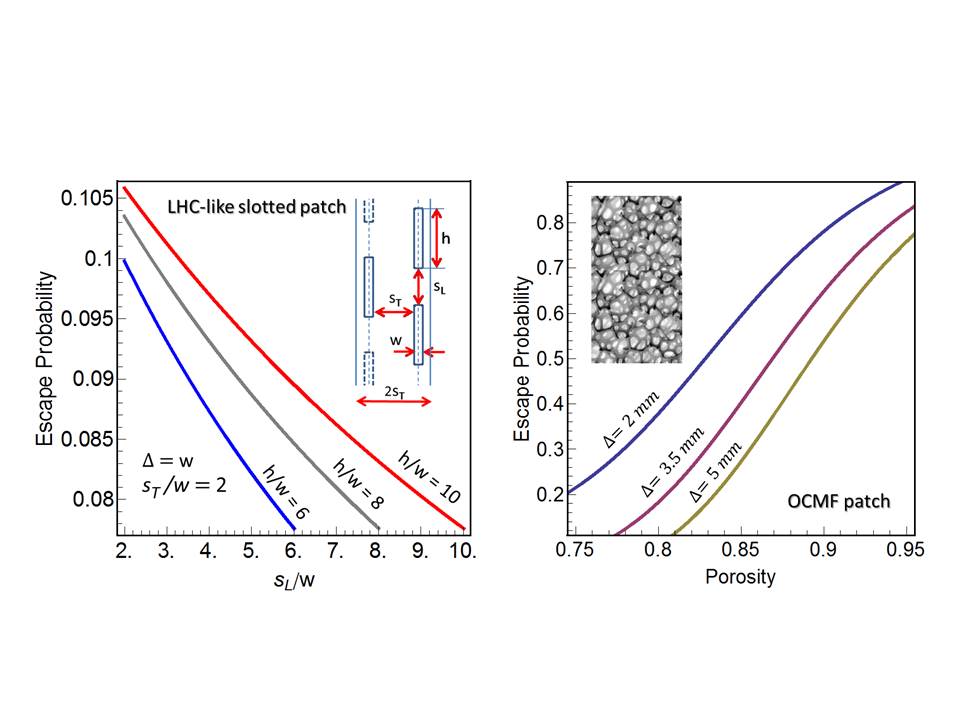
The escape probability of an LHC-like slotted patch (strip) is displayed
in the left panel of Figure 5.
Stiffness requirements set a lower limit
to the axial () and transverse () slot spacings at
roughly twice the slot width .
In figure 5 we assume and
plot the escape probability vs. the scaled longitudinal slot separation ,
for three typical values of the slots height-to-width ratio .
The wall thickness is assumed as equal to , yielding a
Clausing factor SteckMan .
In the LHC the slotted strips represent roughly one half of the liner surface.
The slots are long, on average, and wide,
with .
The holey fraction of the total liner surface is roughly , and the
escape probability is .
III.1.2 Liner with OCMF Patches
Gas permeability of OCMFs in the molecular flow regime
is described by Knudsen diffusivity Steckel .
The dependence of this latter on foam porosity
was fitted numerically in Murch1 and Murch2 ,
using computer simulations of molecular diffusion
based on tomographic data of actual OCMF specimens.
An exponential blow up of Knudsen diffusivity was observed,
above some porosity threshold, possibly
due to the creation of long-range molecular pathways.
From Knudsen diffusivity the escape probability of OCMF patches
can be readily obtained, using Fick’s (diffusion) law,
and is displayed in Figure 5
(right panel) as a function of porosity, for different values
of the OCMF wall thickness .
It is seen from Figure 5 that typical OCMF patches,
e.g., with ,
feature fairly larger escape probabilities,
compared to slotted patches.
OCMF walls are also expected to provide better EM shielding
compared to slotted ones. Hence, gas molecules sticking inside the
foam pores will be less exposed to recycling, resulting into possibly smaller values
of the recycling factor in (12) and (14).
III.2 Beam Coupling Impedance and Parasitic Losses
Beam coupling impedances provide a synthetic description of the electromagnetic beam-pipe interaction. Here, for the sake of brevity, we shall confine our discussion to the longitudinal impedance. The absolute value and the imaginary part of this latter are inversely proportional to the threshold currents for (single-bunch) microwave instability and Landau damping suppression, respectively, and hence quite relevant to beam stability Zotter , while the real part determines the parasitic loss (energy lost by the beam per unit pipe length), via Zotter
| (15) |
where and
are the beam-current spectrum and longitudinal impedance per unit lenght,
respectively.
The following relationship exists
(to 1st order in the wall impedance)
between the longitudinal impedance per unit length
of a patched-wall beam liner
and the (known) longitudinal impedance per unit length
of the same pipe with a perfectly conducting wall Partacc
| (16) |
where is the (local) Leontóvich impedance Leont of the patched wall,
is the pipe cross-section contour,
the vacuum admittance,
the beam linear charge density,
and the (known) field component
normal to the pipe wall in the perfectly conducting pipe777
A similar formula exists for the (dyadic) transverse impedance Partacc ..
According to (16), perforated/slotted or OCMF patches
placed where the normal field component is minimum
will have minimum impact on the longitudinal impedance.
Hence, a circular beam liner, featuring a uniform field along ,
represents a worst case, where the longitudinal (and transverse)
beam coupling impedances is simply proportional to the average of the
wall impedance, assumed as piecewise constant
| (17) |
being the surface fraction covered by patches with wall impedance .
Impedance of Perforated Patch
The effective wall impedance of a perforated patch can be computed under the Bethe approximation where the holes/slots are (much) smaller than the shortest wavelength in the beam spectrum, yielding Kurennoy , holes
| (18) |
being the vacuum characteristic impedance,
the total internal polarizability of the holes/slots,
and their surface density.
In Gluck the more general case, relevant for the LHC,
of a circular perforated liner with inner radius and thickness
surrounded by a circular co-axial lossy tube (the cold bore)
with radius was investigated.
It was found that the liner wall impedance
can still be cast in the form of eq. (18),
after the formal substitution
| (19) |
where the superfix identifies the total external polarizability of the holes/slots in wall with thickness , and holes , Gluck
| (20) |
being the cold bore wall impedance 888
In this formula is the impedance of both
the the cold bore and outer beam-liner walls..
The wall reactance is negligibly affected by the presence of the
external tube, which produces a small resistive component,
accounting for radiation leakage throught the slots.
We use the following formulas from for thin axial slots from KurKEK :
| (21) |
where is the total polarizability of
a slot in a vanishingly thin wall, and
all other symbols are defined in Figure 5.
Impedance of OCMF Patch
A straightforward solution, which is not included for brevity, of the electromagnetic boundary value problem for a (relativistic, vanishingly thin) axial beam in a circular conducting foam liner, with radius and thickness surrounded by a co-axial (infinitely thick) conducting circular tube (the cold bore) with radius , shows that if exceeds a few skin depths across the whole beam current spectrum, which is certainly the case here, as seen from eq. 7, the Leontóvich impedance of the OCMF liner wall is fairly well approximated by the intrinsic impedance of the OCMF, viz., (compare w. eq (6)
| (22) |
The surface roughness of the foam also contributes to the OCMF wall impedance. The order of magnitude of this contribution can be estimated from BaStu_rough
| (23) |
and being the r.m.s. height and correlation
length of the surface roughness, respectively.
Impedance Budget
For illustrative purposes,
the numerical values of the real and imaginary components
of the relevant wall impedances, normalized to the mode number
(i.e., multiplied by the factor),
have been collected in Table III.
Here we assume high-grade Copper
( at )
for the solid, slotted, and foam-matrix metal.
The numbers in Table III for the slotted-patch
are obtained for the slot geometry depicted in Figure 5, with
, and ,
for which , and the escape probability
reaches its the fiducial upper limit .
The numbers for the foamed patch are obtained assuming
a typical pore diameter , and a typical
ligament size , yielding
and
in the Drude model of Section II.1.1,
consistent with typical measured values of
the static conductance of open-cell Copper foams.
We assume a typical r.m.s. roughness scale
and a correlation length .
| Solid Copper | OCMF | OCMF | Slotted Patch | |
|---|---|---|---|---|
| Patch | Patch | Roughness | (Perfect Conductor) | |
| ) |
As seen from Table III,
the Copper wall resistance is larger than that of the OCMF
up to .
On the other hand, as anticipated in Section II.1.1,
the OCMF wall reactance is relatively large,
and exceeds significantly that of a perfectly conducting slotted wall
as well as that of solid Copper.
However, as seen from Figure 5, a typical OCMF wall pumping capacity
(escape probability) is several times larger than that of the
”best” slotted wall.
Thus, to obtain the same pumping capacity, the patched
beam-liner surface needed in the OCMF case is only a small fraction
of that for the slotted case.
This makes easier to place the OCMF patches where the (unperturbed) field
in eq. (16) is minimum, so as to minimize their impact
on the beam coupling impedance.
III.3 Secondary Emission Yield
Perforations reduce the secondary emission yield (SEY)
of a metal wall by a factor roughly proportional
to the solid fraction of the surface roughSEY .
The SEY of metals is strongly reduced by surface roughening,
obtained, e.g., by powder blasting ecloud2 .
For the special case of periodic rectangular grooves etched on a flat metal surface,
the SEY dependence on the groove depth-to-spacing and width-to-thickness ratios
has been investigated, indicating that larger ratios yield a smaller SEY Pivi .
Carbon coating also reduces SEY effectively Carbon , at the expense
of some increase in wall resistance.
It is reasonable to expect that OCMFs
may exhibit a much lower SEY compared to solid metals
in view of their random-like surface roughness.
The SEY of an OCMF wall will depend on the effective roughness
of its surface, which is a function of the foam porosity
and average pore size.
OCMF surface roughness, however, should be kept small enough,
to prevent the blow up of wall rectance.
No measurements of the SEY of OCMFs are available yet,
to the best of our knowledge, but should be straightforward SEYmeasu .
IV CONCLUSIONS
On the basis of the above discussion, some tentative conclusions can be drawn
about the possible use of OCMF materials in the
beam liners of high synchrotron radiation accelerators.
The outgassing capabilities of OCMF patches can be better
by a factor compared to the ”best” slotted patches,
and would accordingly allow to boost the molecular escape probability
of beam pipes by roughly one order of magnitude,
compared to present designs,
while keeping the patched fraction of the beam-liner surface unchanged.
The mechanical-structural properties of conducting foams should also be adequate
to resist to eddy-current induced stresses,
in view of their very morphology.
A low SEY is also expected, due to OCMF surface roughness, even though
no experimental results are available yet.
The OCMF surface resistance is very low, and almost frequency independent.
On the other hand, the (inductive) wall reactance of an OCMF patch
is larger by roughly one order of magnitude compared to that of a perforated
wall with comparable escape probability.
This drawback could be mitigated by clever placement of the OCMF
patches, and/or appropriate reactive loading
of the (solid portion of) the pipe wall.
In order to translate the above hints into effective design criteria,
further modeling effort and substantial experimental work are in order.
Measurement of the complex surface impedance and SEY of metal foams
are now underway Cimmin .
We believe that such an effort is worth being pursued,
and that the available modeling tools and technologies provide a good starting point
for its successful implementation.
Acknowledgements
This work has been sponsored in part by the Italian Institute for Nuclear Physics (INFN) under the IMCA grant. Stimulating discussions with F. Zimmermann and G. Rumolo (CERN) are gratefully acknowledged.
References
- (1) A. Valishev, ”Synchrotron Radiation Damping, Intrabeam Scattering and Beam-Beam Simulations for HE-LHC,” arXiv:1108.1644v1 [physics.acc-ph] (2011).
- (2) A. Blondel et al., ”LEP3: A High Luminosity e+e- Collider to Study the Higgs Boson,” arXiv:1208.0504v2 [physics.acc-ph] (2012).
- (3) - ”The Large Hadron Collider Conceptual Design,” CERN Rept. AC/95-05 (1995).
- (4) B.W. Zotter and S.A. Kheifets, ”Impedances and Wakes in High Energy Particle Accelerators,” World Scientific, Singapore (1998).
- (5) S. Heifets and A. Mikhailichenko, ”Coherent Synchrotron Radiation in Multiply Connected Vacuum Chamber,” SLAC Pub. 8428 (2000).
- (6) I. Montero et al., ”Lowering SEY by Rough Surfaces,” Proc. CERN Anti e-Cloud Coating AEC ’09, paper #29.
- (7) F. Zimmermann, ”Review of Single Bunch Instabilities Driven by an Electron Cloud,” PRST-AB 7 (2004) 124801.
- (8) K.C. Harkay, ”Observation and Modeling of Electron Cloud Instability” Proc. EPAC ’06, Edinburgh UK, paper id. WEXFI02 (2006).
- (9) J. Banhart and N.A. Fleck, ”Cellular Metals and Metal Foaming Technology,” MIT Press, Boston (2003).
- (10) www.ergaerospace.com
- (11) D. Weaire and R. Phelan, ”A Counter-Example to Kelvin’s Conjecture on Minimal Surfaces,” Phil. Mag. Lett. 69 (1994) 107.
- (12) www.imorph.sourceforge.net
- (13) T. Weiland, ”A Discretization Method for the Solution of Maxwell’s Equations for Six-Component Felds,” AEU Int. J. Electr. C31 (1977) 116.
- (14) H. Zhang et al., ”Numerical Predictions for Radar Absorbing Silicon Carbide Foams Using a Fnite Integration Technique with a Perfect Boundary Approximation,” Smart Mater. Struct. 15 (2006) 759.
- (15) F.G. Cuevas et al., ”Electrical Conductivity and Porosity Relationship in Metal Foams,” J. Porous. Mater. 16 (2008) 675.
- (16) R. Goodall, L. Weber and A. Mortensen, ”The Electrical Conductivity of Microcellular Metals,” J. Appl. Phys., 100 (2006) 044912.
- (17) D.A.G. Bruggemann, ”Berechnung Verschiedener Physikalischer Konstanten von Heterogenen Substanzen,” Ann. Phys. 24 (1935) 636.
- (18) R. McLaughlin, ”A Study of the Differential Scheme for Composite Materials,” Int. J. Eng. Sci. 5 (1977) 237.
- (19) Y. Qui and G.J. Weng, ”On the Application of Mori–Tanaka’s Theory Involving Transversely Isotropic Spheroidal Inclusions,” Int. J. Eng. Sci. 28 (1990) 1121.
- (20) S.K. Kanaun, ”Dielectric Properties of Matrix Composite Materials with High Volume Concentration of Inclusions (Effective Field Approach),” Int. J. Eng. Sci. 41 (2003) 1287.
- (21) I. Sevostianov, J. Kovacic and F. Simancik, ”Elastic and Electric Properties of Closed Cell Aluminum Foams,” Mat. Sci. Eng. A420 (2006) 87.
- (22) T. W. Clyne, ”Thermal and Electrical Conduction in MMCs,” in ”Comprehensive Composite Materials,” Elsevier, Amsterdam (2000).
- (23) D. Stauffer and A. Aharony, ”Introduction to percolation Theory,” Taylor and Francis, London (1992).
- (24) G. Monti et al., ”New Materials for for Electromagnetic Shielding: metal Foms with Plasma Properties,” Microwave Opt. Technol. Lett., B52 (2010) 1700.
- (25) J.B. Pendry et al. ”Low Frequency Plasmons in Thin-Wire Structures,” J. Phys. Cond. Matt. 10 (1998) 4785.
- (26) M.A. Ordal et al., ”Optical Properties of the Metals and in the Infrared and Far Infrared,” Appl. Optics 22 (1983) 1099.
- (27) H. Day et al., paper WEPPR070, Proceedings of IPAC2012 (2012)
- (28) E.S. Reddy and G.J. Schmitz, ”Superconducting Foams,” Supercond. Sci. Technol. 15 (2002) L21.
- (29) E.S. Reddy et al., ”Processing of Foams,” Supercond. Sci. Technol. 16 (2003) 608.
- (30) E. Bartolomé et al.,”Critical State in Superconducting Single-Crystalline Foams: Local versus Long-Range Currents,” Phys. Rev. B 70 (2004) 144514.
- (31) D.N. Basov et al., ”Electrodynamics of High- Superconductors,” Rev. Modern Phys 77 (2005) 721.
- (32) C.A.M. dos Santos et al., ”Two Fluid Model for Granular Superconductors,” Phys. Rev. B74 (2006) 184526.
- (33) J.H. Ma and I. Wolf, ”Modeling the Microwave Properties of Superconductors,” IEEE Trans.MTT-42 (1985) 1053.
- (34) J.G. Noudem, ”Magnetic and Transport Properties of Superconductor Foams,” Physica C390 (2003) 286.
- (35) O. Gröbner, ”Overview of the LHC Vacuum System,” Vacuum 60 (2001) 25.
- (36) W. Steckelmacher, ”Knudsen Flow 75 Years on: the Current State of the Art for Flow of Rarefied Gases in Tubes and Systems,” Rep. Progr. Phys. 49 (1986) 1083.
- (37) O Malyshev, CERN ”LHC Vacuum Technical Note 01-06,” (2001).
- (38) W. Steckelmacher and K.F. Man, ”Molecular Flux Distribution in the Detector Plane of an Effusive Source Molecular Beam Apparatus,” Rev. Sci. Instrum. 56 (1985) 58 (1985).
- (39) T. Fiedler et al., ”Numerical Simulation of Knudsen Diffusion in a Metallic Foam,” Comput. Mat. Sci., 50 (2011) 1795.
- (40) T. Fiedler et al., ”A Comparative Study of Knudsen Diffusion in Cellular Metals,” Comput. Mat. Sci., 50 (2011) 2666.
- (41) S. Petracca, ”Reciprocity Theorem for Coupling Impedance Computation in the LHC Liner.,” Particle Accel. 50 (1995) 211.
- (42) A.M. Dykne and I.M. Kaganova, ”The Leontovich Boundary Conditions and Calculation of Effective Impedance of Inhomogeneous Metal,” Opt. Comm. 206 (2002) 39.
- (43) S.S. Kurennoy, ”Coupling Impedance of Pumping Holes,” Particle Accel. 39 (1992) 1.
- (44) S. Petracca, ”Beam Coupling Impedances for Perforated Beam Pipes with General Shape from Impedance Boundary Conditions,” Phys. Rev. E60 (1999) 6030.
- (45) R.L. Gluckstern and B.W. Zotter, ”Energy loss to Coaxial Vacuum Chambers in LEP and LHC,” CERN Rept. SL 96/56 (AP) 1996.
- (46) S. Kurennoy, ”Coupling Impedances and Heating due to Slots in the KEK B Factory,” KEK-preprint 94-193 (2005).
- (47) K.L.F. Bane and G.V. Stupakov, ”Wake of a Rough Beam Wall Surface,” SLAC Pub. 8023 (1988).
- (48) M. Pivi et al., ”Sharp Reduction of the Secondary Electron Emission Yield from Grooved Surfaces,” SLAC Pub. 13020 (2007).
- (49) C.Y. Vallgren et al., ”Amorphous carbon coatings for the mitigation of electron cloud in the CERN Super Proton Synchrotron,” Phys. Rev. STAB 14 (2011) 071001.
- (50) F. Caspers et al., ”RF Test Benches for Electron Cloud Studies,” Proceedings EPAC ’02, Paris, FR, paper id WEPDO031 (2002).
- (51) R. Cimino, S. Petracca and A. Stabile, work in progress.