First results from the FPGA/NIOS Adaptive FIR Filter Using Linear Prediction Implemented in the AERA Radio Stations to Reduce Narrow Band RFI for Radio Detection of Cosmic Rays
Abstract
The FPGA/NIOS® FIR filter based on linear prediction (LP) to suppress radio frequency interference (RFI) has been installed in several radio stations in the Auger Engineering Radio Array (AERA) experiment. AERA observes coherent radio emission from extensive air showers induced by ultra-high-energy cosmic rays to make a detailed study of the development of the electromagnetic part of air showers. Radio signals provide complementary information to that obtained from Auger surface detectors, which are predominantly sensitive to the particle content of an air shower at the surface. The radio signals from air showers are caused by the coherent emission due to geomagnetic and charge-excess processes. These emissions can be observed in the frequency band between 10 - 100 MHz. However, this frequency range is significantly contaminated by narrow-band RFI and other human-made distortions. A FIR filter implemented in the FPGA logic segment of the front-end electronics of a radio sensor significantly improves the signal-to-noise ratio. Theoretical calculations show a high efficiency of this filter for mono-carrier as well as for standard FM radio contaminations. The laboratory tests, performed on the Altera® Cyclone® V DK-DEV-5CEA7N development kit confirmed the theoretical expectations.
In this paper we present first results of the efficiency of the adaptive LP FIR filter, deployed in real AERA station on pampas, with a comparison to the currently used IIR notch filter with constant coefficients. The coefficients for the linear predictor are dynamically refreshed and calculated in a Voipac PXA270M ARM processor, which is implemented on a daughter-board placed in the same digital unit as the FPGA. The laboratory tests confirms the stability of the filter. Using constant LP coefficients the suppression efficiency remains the same for hours, which corresponds to more than clock cycles. We compared in real conditions several variants of the LP FIR filter with various lengths and various coefficients widths (due to fixed-point representations in the FPGA logic) with the aim to minimize the power consumption for the radio station while keeping sufficient accuracy for noise reduction.
The laboratory and real condition tests provide data to optimize the RFI cleaning for the next generation of the AERA Front-End based on Cyclone® V with Hardcore Processor System (HPS) and System on Chip (SoC).
I Introduction
Recently radio detection of cosmic-ray air showers relives a renaissance, mainly thanks to a huge progress of the powerful digital signal processing techniques in experiments such as LOPES [1], CODALEMA [2] or the Auger Engineering Radio Array (AERA) [3], which is situated within the Pierre Auger Observatory (PAO) [4].
Results from the Pierre Auger Observatory, point to the need for very large aperture detection systems for ultra-high energy cosmic rays. With its nearly 100% duty cycle, its high angular resolution, and its sensitivity to the longitudinal air-shower evolution, the radio technique is particularly well-suited for detection of ultra-high energy cosmic rays (UHECRs) in large-scale arrays. AERA has been enlarged to 124 radio detector stations (RDSs), covering an area of 6.5 km2 therefore allowing the detection of UHECRs.
Since the 1960s we know that the radio emission from air showers is strongly correlated with the local geomagnetic field [5]. In addition to the geomagnetic effect that can be described macroscopically [6], Askaryan [7] [8] predicted that there should be an emission component related to the time-variation of the negative net charge excess in air showers. Both [1] and [2] confirmed these effects. Using the AERA setup, the Auger collaboration quantified the relative strength of these effects [9] The observation of air showers with radio-detection techniques can be done at almost all times. Moreover, radio signals are sensitive to the development of the electromagnetic component of particle showers in the atmosphere of the Earth. In the last 10 years the radio-detection technique in the MHz region has been revived and the present radio-detector arrays for cosmic-ray research are equipped with low-noise and high-rate digital samplers. Simultaneously, the number of stations within these arrays has grown from less than ten to more than one thousand. The question to be addressed in the VHF band (MHz-range) is not whether extensive air showers emit radiation. At this moment the main question to answer is: can we use radio signals to determine the primary energy, the arrival direction, and the mass of cosmic rays with accuracies which are equal to or better than those obtained by other techniques? And if yes, can we build for an affordable price a huge surface-detector array based on the radio-detection technique?
II RFI suppression for real AERA data
Triggering directly on the radio signal of the air showers (instead of using particle detectors as a trigger) poses some challenges for the data acquisition, due to man-made radio-frequency interference (RFI). The continuous background level is set by the radio emission from the Galactic plane, but any man-made narrow band transmitters add to the level above which one must detect air-shower pulses. Additionally, man-made pulsed RFI (from sparking electrical equipment, airplanes, etc.) can mimic the short pulsed signal from cosmic rays. Since the bandwidth and computational resources at each triggering level are limited, one of the technical focuses for the first stage of the array has been to develop various methods to reject RFI in order to minimize efficiency losses from bandwidth saturation.
The energy threshold of radio detection of cosmic rays is limited by the considerable radio background and noise. The very high level of RFI in the FM and short wave band has to be eliminated by a band pass filter. Within the remaining receiver bandwidth of 30 to 80 MHz the noise at the quiet-rural environment of the Pierre Auger Observatory is dominated by the frequency dependent galactic noise [10] with noise temperatures of 5000 K at 60 MHz
In addition to the galactic noise, there is a human made background. This background consists of continuous signals, as from a few radio and TV stations, and transients produced by machines. Without an effective trigger, a stable and low level energy threshold is not guaranteed. Furthermore, the data rate for communication of the triggered data to the central DAQ would exceed the available bandwidth.
II-A FFT + Median filter + iFFT
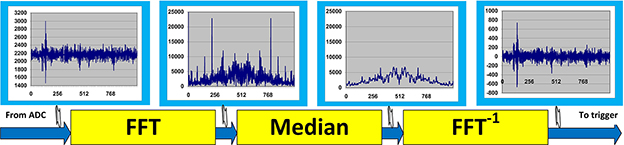
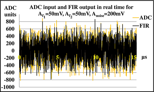
For self-triggered measurements, the data will be digitized and processed in real time by a powerful FPGA chip. The narrow peaks in the frequency domain due to radio frequency interferences have to be strongly suppressed before building a trigger. These peaks are removed in several stations, digitizing at 180 MHz, using a median filter. The filter works in the frequency domain using the Fast Fourier Transform (FFT) routine provided by Altera . Furthermore, the phase of the signal deformed by the steep band pass filter is reconstructed by a deconvolution in the frequency domain. The median FPGA filter eliminates mono-frequent carriers, but broadband radio pulses from cosmic showers are not affected. After a second inverse FFT, signals are converted back to the time domain. This chain of the digital signal processing strongly enhances the signal to noise ratio, and thus improves the radio pulse detection sensitivity (Fig. 1).
In order to suppress the strong man-made radio carrier signals below 30 MHz and above 80 MHz and to fulfill the Nyquist theorem, the signals of the antennas are filtered using an analogue band filter before being sampled by the ADCs. The filters with the constant transfer function are of high order with a non-constant group delay, thus leading to a dispersion and decreasing the amplitude of the input signals . In a frequency domain, the resulting output signal can simply be calculated using (1) :
| (1) |
Knowing from measurements, it is now easy to get back by inverting (1). This operation can be implemented into the FPGA by placing a complex multiplication unit directly after the FFT engine which multiplies the output data of the engine with the precomputed coefficients of stored in a RAM. After transforming the signal back into the time domain, the amplitude of the de-convoluted signal increases by about 20% compared to the input signal. Since the galactic and electronic noise is completely uncorrelated, the S/N ratio increases by the same amount.
Aliasing appears when converted pulses are located close to a border of converted blocks. It manifests by a spurious contribution in the opposite border of the block and in the neighboring block as well. This effect may cause spurious triggers and has to be eliminated.
The problems can only be solved, without introducing dead time between the blocks, by using an overlapping routine. Therefore the filter engine must run in another clock domain with higher frequency (210 MHz instead of 180MHz). Nevertheless, it requires additional resources e.g. FILO (First In Last Out) memory based procedure to inverse in time a sequence of samples. The FFT approach is generally very power consuming. This is a factor for a system supplied from solar panels.
II-B IIR notch filter
As stated earlier, before triggering on a radio pulse it is advantageous to increase the signal-to-noise ratio by filtering out any narrow band transmitters from the digitized antenna signals. In stations digitizing at 200 MHz, this is accomplished in a computationally efficient manner by using a series of infinite-impulse response (IIR) notch filters in a Cyclone®-IV FPGA. The IIR filters operate on the time-domain signal, and the output of the filter is a linear combination of input samples and delayed feedback output samples from the filter:
| (2) | |||||
The normalized filter frequency is given by the notch frequency and the sampling frequency . The width parameter, r, is provided with a value strictly between 0 and 1, with higher values giving a narrower response function. For a narrow transmitter a typical value is r=0.99. A complication in the implementation of the IIR filters in high-frequency FPGAs arises from the fact that one cannot arbitrarily pipeline the feedback computation. We have resolved this by using the scattered look-ahead pipelining technique [11], which increases the filter complexity but allows more time for computation in the FPGA.
The coefficients of the and in Eq. 2 can be precomputed for the desired notch frequencies, converted to a fixed-point representation and loaded into the FPGA at run-time. The current design allows for four independent tunable notch filters for each polarization direction and is applied on a Cyclone® III, IV and V FPGA. It has been operating in the field for several years and successfully decreased and stabilized the threshold settings.

II-C Linear predictor
Linear prediction is a mathematical operation where future values of a discrete-time signal are estimated as a linear function of previous samples [12]. This method is widely used in audio signal processing and speech processing for representing the spectral envelope of a digital signal of speech in compressed form, using the information of a linear predictive model [13]. With the advent of faster signal processing techniques in FPGAs it is now possible to apply similar techniques to the real-time processing of radio signals in the 10 - 100 MHz region [14].
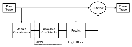
In the LP method the covariances for 1024 ADC samples can be calculated in the FPGA fast logic block. Either the NIOS® processor, or the external ARM-processor, solves the matrix of 32 or 64 linear equations and provides coefficients needed for the FIR filter. The calculated coefficients are next transferred to the fast logic block, updating appropriate registers. They are used as the FIR coefficients in the ADC data filtering. Finally, the predicted and delayed data (expected background) are subtracted from the ADC data to clean the signal from periodic contaminations (Fig. 2).
Comparison of graphs in [16] indicates that the LP approach can eliminate RFI narrow frequency contaminations as efficient as notch and FFT filters.
III Analysis of AERA events
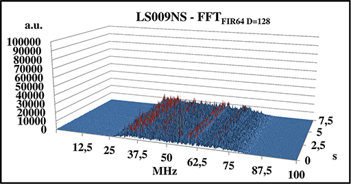
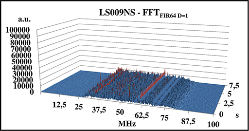
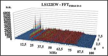
Figures 4 - 5 show spectra of original ADC traces and cleaned by the LP FIR filter with various values for parameter D of 128, 32 and 1, respectively (Fig. 3). For the mono-carrier contamination (Fig. 4) the RFI suppression is very good for any D parameter. For more structured spectral contaminations the suppression depends on the D parameter , nevertheless, we observe a reduction of periodic noise.
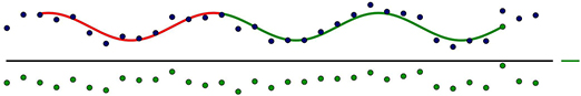
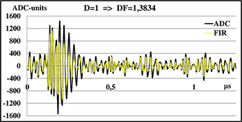
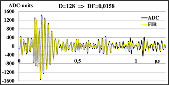
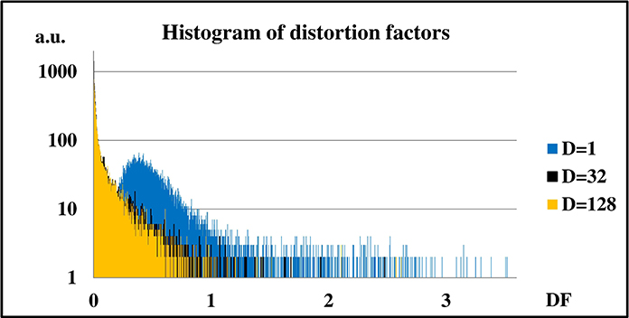
The delay-line implies that there is a gap between the samples that are used for the prediction and the sample that is to be predicted (Fig. 3). This delay-line is necessary to allow transient signals to pass through the filter unaltered. For D=1 the efficiency of the RFI suppression is maximal, however, the signal is significantly affected and a distortion factor (DF) (Fig. 6),
| (3) |
introduced to estimate a quality of filtering, reaches a large, unacceptable value. For laboratory tests we selected D=128, to keep a reasonable safety margin in measurements (Fig. 7).
IV Laboratory tests
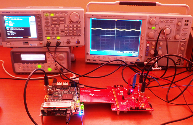
The LP FIR filter has been tested with the Altera® DK-DEV-5CEA7N Development Kit with a Cyclone® V FPGA and Texas Instr. ADS4249EVM Evaluation Module with 2-channel 14-bits 250MSps ADC (ADS4249). Both modules were connected through the Altera® HSMC-ADC-BRIDGE providing the LVDS data transmission (Fig. 17).
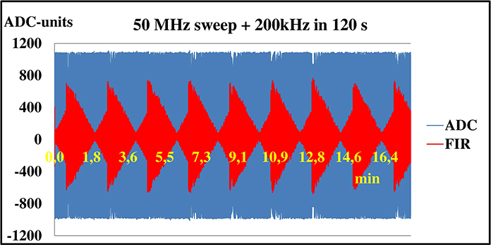
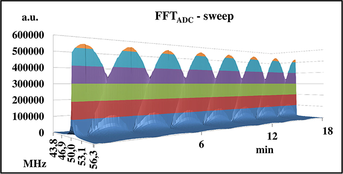
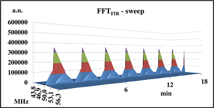
At first the filter was tested by a mono-carrier drifting the frequency from 50.0 MHz to 50.2 MHz in 120 s. The LP coefficients were not calculated by NIOS® in a correlation with a generator running. Thus, these LP coefficients were used for the data cleaning in several tens of minutes (which corresponds to more than clock cycles). Fig. 8 shows a perfect long-term stability of the filter. If the generator driving the filter uses the frequency for which the LP coefficients were originally calculated, the suppression is almost total. Therefore, LP coefficients do not need to be refreshed very frequently.
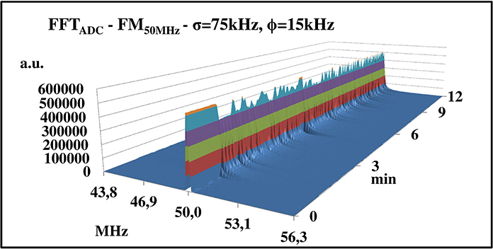
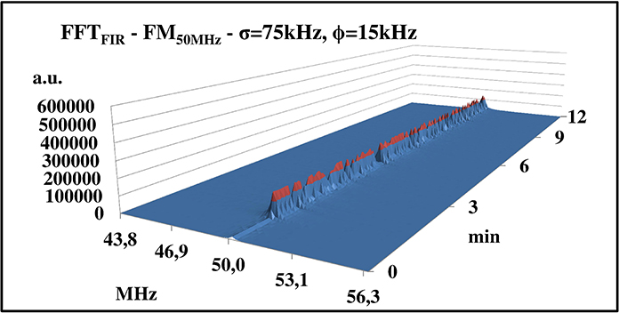
Secondly, we checked the Hi-Fi FM configuration (75 kHz deviation of the 50 MHz carrier with the maximal acoustic 15 kHz modulation). This is very restrictive condition, which actually should not appear in real conditions in Argentina. The band 30 - 80 MHz is used rather by narrow-band transmitter, while the FM Hi-Fi transmission is selected for the band of 88 - 108 MHz, cut-off by the band-pass analog filter. Nevertheless, even these critical contaminations were successfully suppressed (Fig. 9).
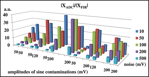
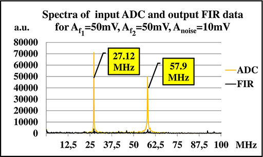
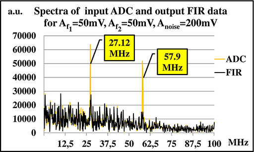
We also tested a suppression efficiency (in the Fourier space) in the presence of relatively strong white noise (Fig. 11). Two pure carriers with 27.12 and 57.9 MHz were wired mixed with noise. Fig. 10 shows that even when the noise level reaches the signal level the suppression factor remains on a level of 5-10 (for signals 50 mV and 200 mV contaminated by 50 mV and 200 mV of a noise). When the noise is small, the suppression factor reaches values up to 35. However, a strong asymmetry is observed. The strong signal (i.e. 200 mV of 27.12 MHz) is suppressed with a very high factor (35) while a 4 times smaller signal (57.9 MHz) is almost not suppressed at all. For vice versa configuration a suppression structure remain the same.
V Comparison to currently used IIR-notch filter
We compared suppression characteristics of the FIR filter based on the linear prediction with the currently used IIR-notch filter with 4 band-reject bands. Fig. 12 shows amplitudes of the frequency bin in the Fourier space corresponding to a contribution of carrier contamination with a various frequencies in a range of 27.00 - 27.24 MHz for a small (10 mV - upper graph) and significant (100 mV - lower graph) noise. It is well visible that the efficiency of the IIR filter is very high and, as expected, only around the reject frequency (27.12 MHz) of the filter. Higher noise (comparison 100 mV vs. 10 mV) reduces the efficiency only slightly, thereby extending the width of the rejection band (from 20 kHz to 30 kHz).
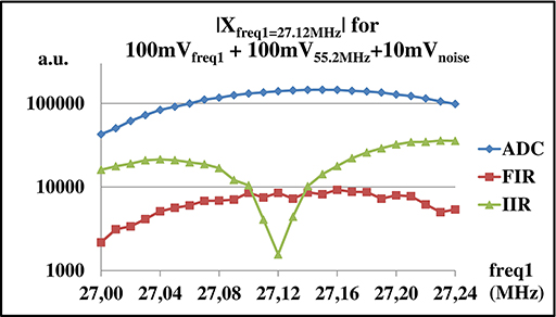
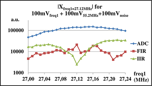
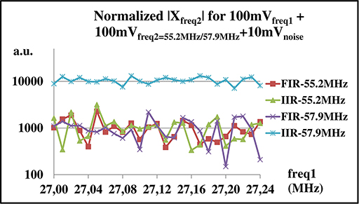
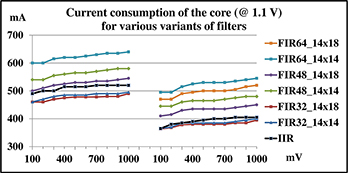
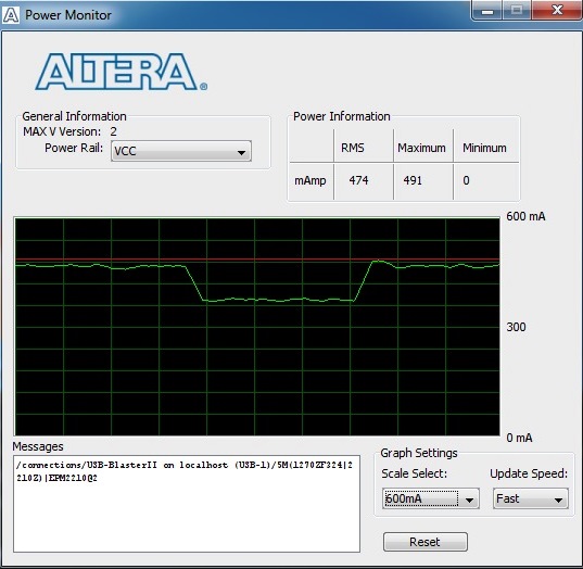
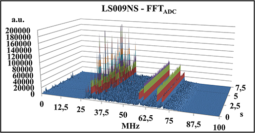
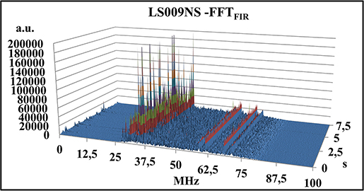

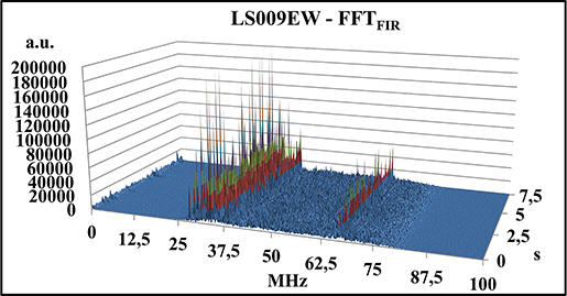
Fig. 13 shows the (55.2 MHz) and (57.9 MHz) Fourier modules vs. various frequencies in the channel contamination (27.00 - 27.24 MHz). As expected, the suppression of the IIR filter outside the reject band is negligible. Note that for structured contaminations (two mono-carriers with frequencies equal exactly the reject frequencies of the IIR-filter) the efficiency of the FIR filter is comparable with the efficiency of the IIR one, provided the background noise level is low in comparison to the contamination.
VI Power consumption
A power consumption is the factor for systems supplied from solar panels. More sophisticated filter provides a better accuracy of data processing. However, the power efficiency may significantly decreased. We measured a power consumption for all developed FIR variants and compared with the currently used IIR filter. Fig.14 shows results for the current consumption with the NIOS processor (left panel) and with temporary blocked NIOS (right panel). The NIOS processor was used for the calculation of LP coefficients for the FIR filter and for data transmission via UART to the PC for both filters Fig.15.
From Fig.14 it is visible that the FIR filter wit 32 stages and only 14-bit coefficients is at least power efficient in comparable to the IIR one. Longer FIR filters consume much more power and could be used exceptionally in extremely contaminated environment, where the suppression efficiency becomes the more important factor than the power efficiency.
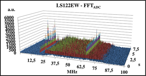
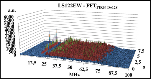
VII Data from pampas
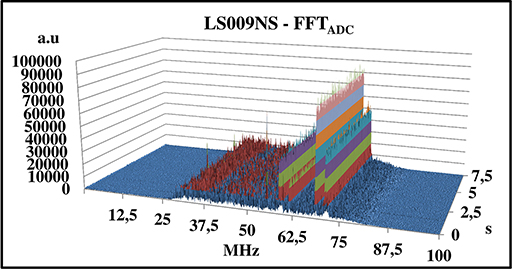
We have implemented the 32-stage LP filter (with D=128) in the AERA radio station LS009. Fig. 16 show a suppression of the RFI in the higher frequency range. In comparison to Fig. 4b the suppression efficiency is lower, however, in current environment the huge contribution of non-stationary RFI was observed. In a presence of variable RFI the efficiency of the LP filter is not so high as for mono-carriers contamination. Fig. 16 shows that the noise suppression for the EW polarization is almost negligible.
VIII Conclusions
Analytical calculations (Fig. 4-5) show that a very high efficiency of the LP filter can be obtained. The laboratory measurements confirmed that when the data is contaminated by mono-carriers, the suppression factor is very high. However, the environmental RFI as encountered in the Pierre Auger Observatory has a much more sophisticated structure. Therefore, the efficiency of the LP-filter significantly decreases.
Nevertheless, in each radio station the filter setup can be calculated, thereby optimizing the suppression factor, depending on the location of each station and the type of RFI contamination.
In AERA the Cyclone® IV FPGA EP4CE75F29I7 is currently in use. The laboratory tests provide input for an optimization of the RFI cleaning for the next generation of the AERA Front-End based on Cyclone® V with Hardcore Processor System (HPS) and System on Chip (SoC).
Acknowledgment
This work was supported by the Polish National Center for Research and Development under NCBiR Grant No. ERA/NET/ASPERA/02/11, by the National Science Centre (Poland) under NCN Grant No. 2013/08/M/ST9/00322, , and by the Ministerie van Onderwijs, Cultuur en Wetenschap, Nederlandse Organisatie voor Wetenschappelijk Onderzoek (NWO), Stichting voor Fundamenteel Onderzoek der Materie (FOM), the Netherlands.
References
- [1] H. Falcke,W. D. Apel, A. F. Badea, et al., ”Detection and imaging of atmospheric radio flashes from cosmic ray air showers”, Nature, vol. 435, pp. 313-316, May 2005.
- [2] D. Ardouin, A. Bell´etoile, D. Charrier, et al., ”Radioelectric field features of extensive air showers observed with CODALEMA” Astropart. Phys., vol. 26, pp. 341-350, Dec. 2006.
- [3] S. Fliescher for the Pierre Auger Collaboration, ”Radio detection of cosmic ray induced air showers at the Pierre Auger Observatory”, Nucl. Instr. Meth., ser. A, vol. 662, pp. 124-129, Jan. 2012.
- [4] J. Abraham et al., [Pierre Auger Collaboration], “Properties and Performance of the Prototype Instrument for the Pierre Auger Observatory”, Nucl. Instr. Meth., ser. A, vol. 523, pp. 50-95, May 2004.
- [5] D. J. Fegan, ”Detection of elusive radio and optical emission from cosmic-ray showers in the 1960s”, Nucl. Instr. Meth., ser. A, vol. 662, pp. 2-11, Jan. 2012.
- [6] F. D. Kahn and I. Lerche, ”Radiation from Cosmic Ray Air Showers”, Proc. Roy. Soc. A, vol. 289, pp. 206-213, Jan. 1966.
- [7] G. A. Askaryan, Journal of Exp. and Theoretical Phys., vol. 14, pp. 441, 1962.
- [8] G. A. Askaryan, ”Coherent Radio Emission from Cosmic Showers in Air and in Dense Media”, Journal of Exp. and Theoretical Phys., vol. 21, pp. 658-659, Jan. 1965.
- [9] A. Aab et al., ”Probing the radio emission from air showers with polarization measurements”, Phys. Rev. D89, 052002, Mar. 2014.
- [10] G. A. Dulk, W. C. Erickson, R. Manning, and J.-L. Bougeret, ”Calibration of low-frequency radio telescopes using the galactic background radiation”, A&A, vol. 365, pp. 294-300, Jan. 2001
- [11] K. K. Parhi and D. G. Messerschmitt, IEEE Trans. on Acoustics, Speech, and Signal Processing, vol. 37, pp. 1099-1117, 1989.
- [12] J. Makhoul, “Linear prediction: A tutorial review” Proc. of the IEEE, vol. 63, no. 4, pp. 561-580, Apr. 1975.
- [13] D. Li, D. O’Shaughnessy, ”Speech processing: a dynamic and optimization-oriented approach”, pp. 41–48. ISBN 0-8247-4040-8 (2003)
- [14] Z. Szadkowski, E.D. Fraenkel, A. M. van den Berg, ”FPGA/NIOS Implementation of an Adaptive FIR Filter Using Linear Prediction to Reduce Narrow-Band RFI for Radio Detection of Cosmic Rays”, IEEE Trans. on Nucl. Science, vol. 60, pp. 3483-3490, Oct. 2013.
- [15] Z. Szadkowski, E.D. Fraenkel, D. Głas, R. Legumina, ”An optimization of the FPGA/NIOS adaptive FIR filter using linear prediction to reduce narrow band RFI for the next generation ground-based ultra-high energy cosmic-ray experiment”, Nucl. Instr. Meth., ser. A, vol. 732, pp. 535-539, June 2013.
- [16] Z. Szadkowski, Ad M. van den Berg, E.D. Fraenkel, D. Głas, J. Kelley, C. Timmermans, T. Wijnen, ”Analysis of the efficiency of the filters suppressing the RFI being developed for the extension of AERA”, 33nd International Cosmic Ray Conference - July 2013 - Rio de Janeiro, Brazil.