New Electrochemical Characterization Methods for Nanocomposite Supercapacitor Electrodes
Abstract
Supercapacitor electrodes fabricated from a nanocomposite consisting of multiwall carbon nanotubes and titanium oxide nanoparticles were characterized electrochemically. Conventional electrochemical characterizations cyclic voltammetry and galvanostatic charge-discharge in a lithium-based electrolyte gave a specific capacitance of 345 F/g at a current density of 0.1 A/g. New electrochemical characterization techniques that allow one to obtain the peak capacitance associated with intercalation and to distinguish between electrostatic and faradaic charge storage are described and applied to the electrode measurements. Finally, the maximum energy density obtained was 31 Wh/kg.
I. Introduction
Supercapacitors, also called ultracapacitors or electrochemical double layer capacitors (EDLCs), bridge the gap between batteries and conventional dielectric capacitors Pandolfo2006 ; G.A.Snook2011 . The most common electrode material is carbon-based and include activated carbon Pandolfo2006 ; Frackowiak2001 ; Zhang2009 , carbon nanotubes M.Kaempgen2007 ; C.Liu1999 ; C.Du2005 ; M.Kaempgen2009 ; E.Frackowiak2000 ; Frackowiak2000 ; Meyyapp2013 , and graphene Biswas2010 ; Y.Wang2009 . To go beyond electrostatic charge storage in the double layer, pseudocapacitive and faradaic components (“faradaic components” henceforth) such as conducting polymers and metal oxides were incorporated into supercapacitors Frackowiak2001 ; R.A.Fisher2013 ; Conway2003 ; Cericola2012 . Two ways of incorporating the faradaic material have been employed, both in an asymmetric (or hybrid) configuration where: (1) a carbon electrode and a faradaic electrode form the two electrodes of a supercapacitor Zheng2003 ; Simon2008 ; Q.Wang2006 ; G.Wang2012 ; Y.Xue2008 ; (2) at least one of the electrodes is a composite material that combines advantages of electrochemical double layer charge storage as well as surface redox or intercalation charge storage V.Khomenko2006 ; Z.Chen2009 ; T.Wang2011 ; K.Zhang2010 ; J.Yan2010 .
Carbon nanotubes (CNT) have a high aspect ratio and form porous networks with good conductivity. As such, they have been implemented as supercapacitor electrodes in many instances in the literature Pandolfo2006 ; Frackowiak2001 ; M.Kaempgen2007 ; C.Du2005 ; M.Kaempgen2009 ; E.Frackowiak2000 ; Frackowiak2000 ; Meyyapp2013 ; C.Niu1997 ; K.H.An2001 . Titanium oxide is a versatile compound and can be found in several energy harvesting and energy storage applications, namely photocatalysis, secondary batteries, and supercapacitors D.V.Bavykin2006 . Among the three polymorphs of TiO2, the crystal structure of anatase can accommodate the most Li+ per TiO2 unit and is an attractive energy storage material due to its Li-intercalation capabilities and cycle life Z.Yang2009 . TiO2 nanowires have been synthesized by hydrothermal methods, functioning as the anode of a supercapacitor with carbon nanotubes acting as the cathode Q.Wang2006 ; G.Wang2012 . These are type (1) asymmetric supercapacitors.
In this study, the application of a nanocomposite containing TiO2 nanoparticles and multiwall carbon nanotubes in a single supercapacitor electrode is reported. Results from conventional as well as new electrochemical characterization methods show not only the various aspects of the energy storage mechanism in the electrode but also the combination of double layer and faradaic capacitance as a synergy that leads to high energy density and good power density in a single electrode.
II. Experimental Section
.1 Conventional Electrochemical Characterization
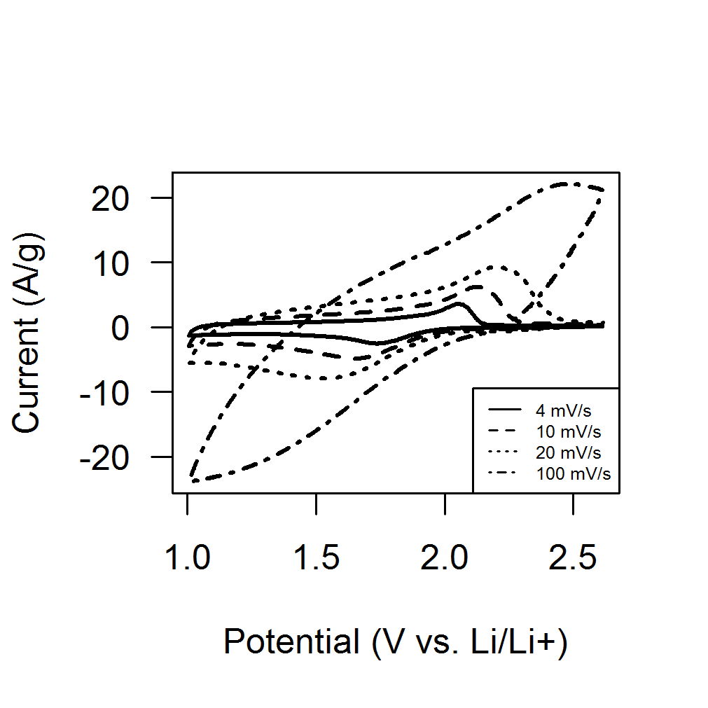
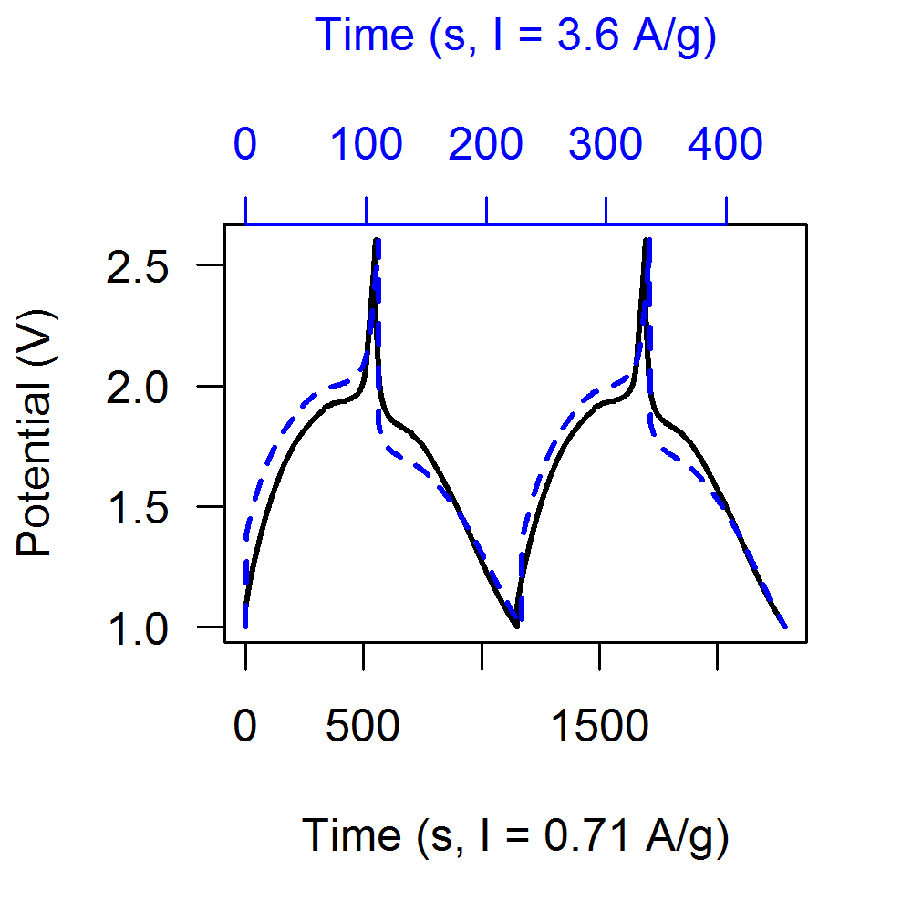
Cyclic voltammetry (CV) as well as galvanostatic cycling (GC) were performed on the CNT-TiO2 composite electrodes. Cyclic voltammetry of the composite electrode at various scan rates was measured in 1 M LiClO4 in propylene carbonate with lithium metal sheets as the reference electrode and counter electrode, shown in Figure 1. The voltage window was 1 V to 2.6 V vs. Li/Li+. A series of galvanostatic measurements were also performed, two of which are shown in Figure 2.
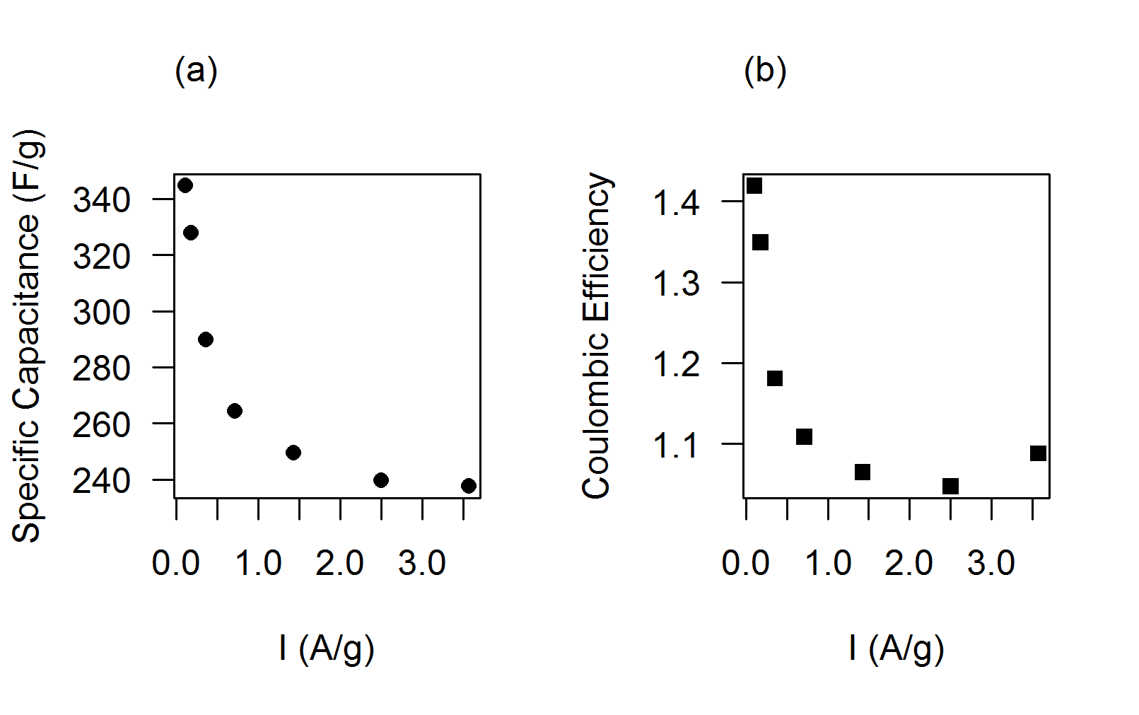
The electrode capacitance is given by and the specific capacitance by . The storage capacity of the composite electrode decreases with increasing current but approaches a constant value, shown in Figure 3 along with the coulombic efficiency.
.2 New Electrochemical Characterization Methods
The galvanostatic charging for a given current is described by
| (1) |
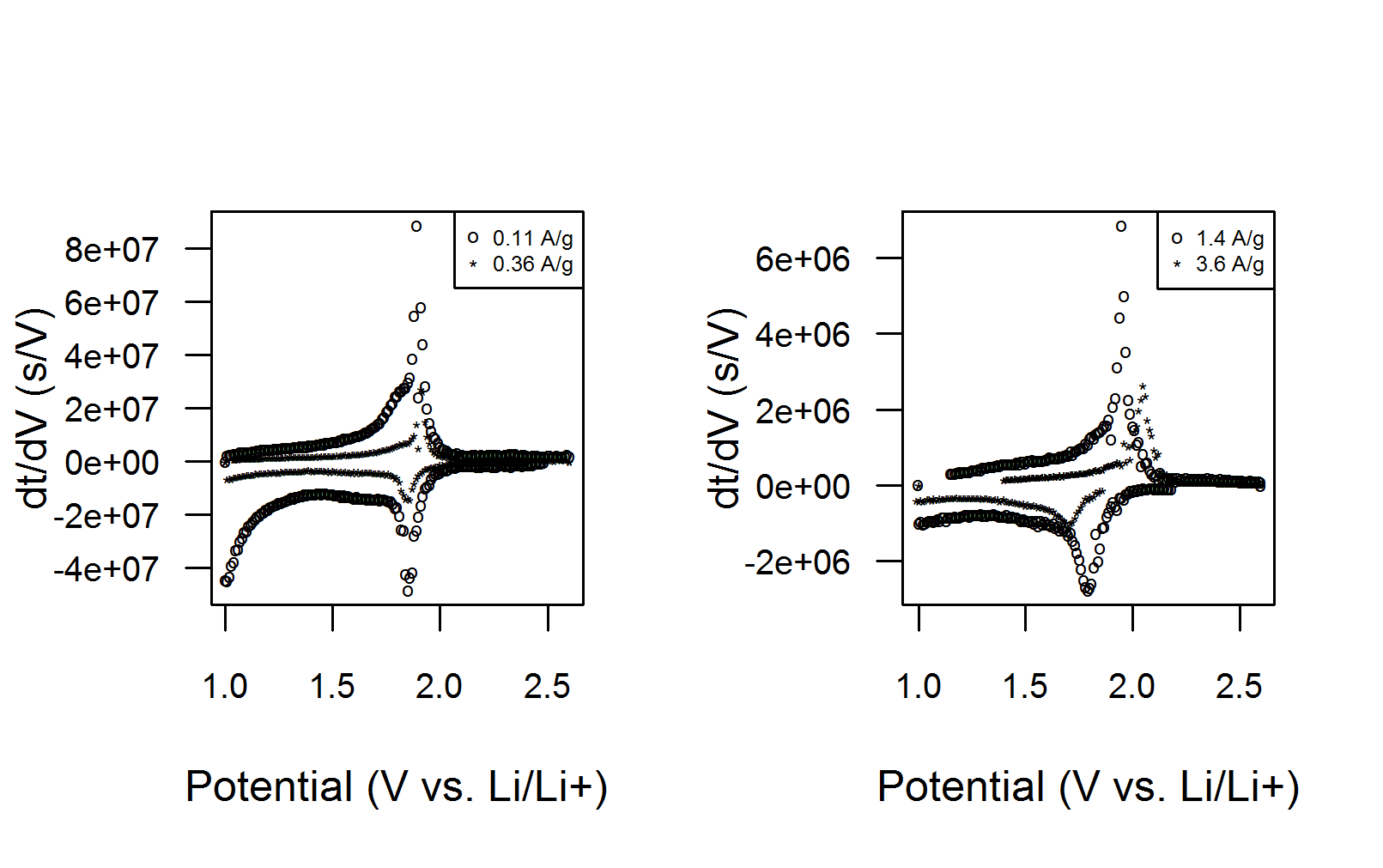
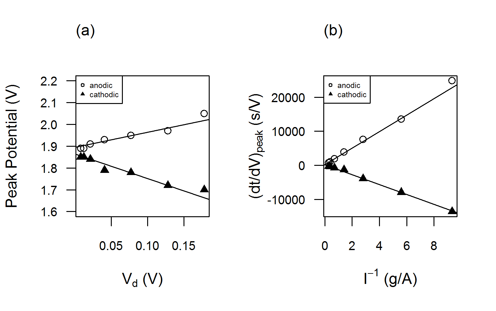
where is the capacitance of the electrode and is the internal resistance. The quantity , denoted by , is the voltage drop at the beginning of charging and discharging cycles. The temporal slope plotted as a function of the potential is shown in Figure 4. These plots will be called temporal slope voltammograms (TSVs) in this article. Similar to CVs, the anodic peaks and cathodic peaks shift as the applied current increases. However, whereas the faradaic/intercalation peaks flatten as the scan rates increase in CVs, the temporal slope peaks remain sharp even for large current densities.
As shown in Figure 5a, as vanishes, both anodic and cathodic peak potentials approach the same value, the standard potential for the intercalation reaction. A plot of the temporal slope peaks versus shows a linear relationship (Figure 5b). Linear regression gives the peak capacitances at , 2410 F/g for Li extraction and 1450 F/g for Li insertion. As a point of reference, the theoretical specific capacitance of TiO2 assuming one Li+ ion per TiO2 molecule is 2295 F/g, calculated using the formula , where is the faraday constant and is the TiO2 molar mass. The peak capacitance at the standard potential of the faradaic reaction could be an important figure of merit in characterizing and optimizing nanocomposites as the mass normalized quantity is nearly independent of the double layer contributions.
In addition to temporal slope voltammograms, a new method to distinguish between electrostatic and faradaic contributions to the energy storage capacity warrants discussion. The distinction is important because one is often interested in the effect of nanoparticle size on the faradaic reactions and whether the faradaic process involves only surface sites or the bulk J.Wang2007 . The differential form of the capacitor equation
| (2) |
includes both capacitor behavior, where the capacitance is a constant that depends only on the capacitorfls geometry and dielectric material, and battery behavior, where the potential is ideally constant and the storage capacity varies linearly with the state of charge. In the case where the potential is the experimentally tunable parameter, charge conservation requires
| (3) |
The current associated with changes in the double layer is given by and the current due to reversible charge transfer reactions at the electrode surface is described by Bard2000
| (4) |
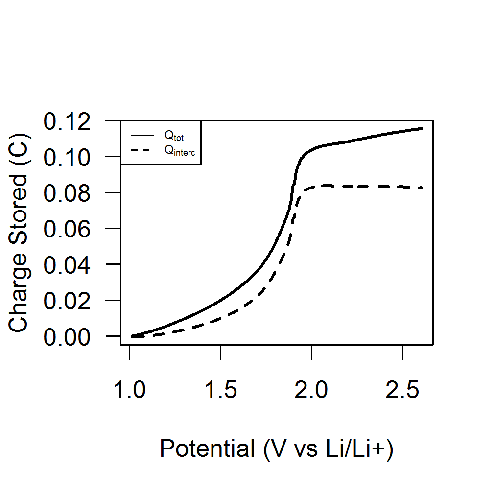
where , is the starting ion concentration at the electrode-electrolyte interface, is the width of the diffusion layer, is the area of the TiO2 nanoparticles, and is the standard potential of the reaction. It follows that the charge stored is
| (5) |
The charge accumulation as a function of potential can be obtained from galvanostatic measurements, as shown in Figure 6. The double layer capacitance can be obtained from the slope of for sufficiently large potentials, after available TiO2 lattice sites are fully intercalated.
III. Results and Discussion
Dielectric capacitors experience changes in potential at a constant storage capacity, whereas batteries experience changes in the storage capacity at a constant potential. The methods outlined in this article enable researchers to electrochemically characterize nanocomposites that exhibit both capacitor-like and battery-like behaviors.
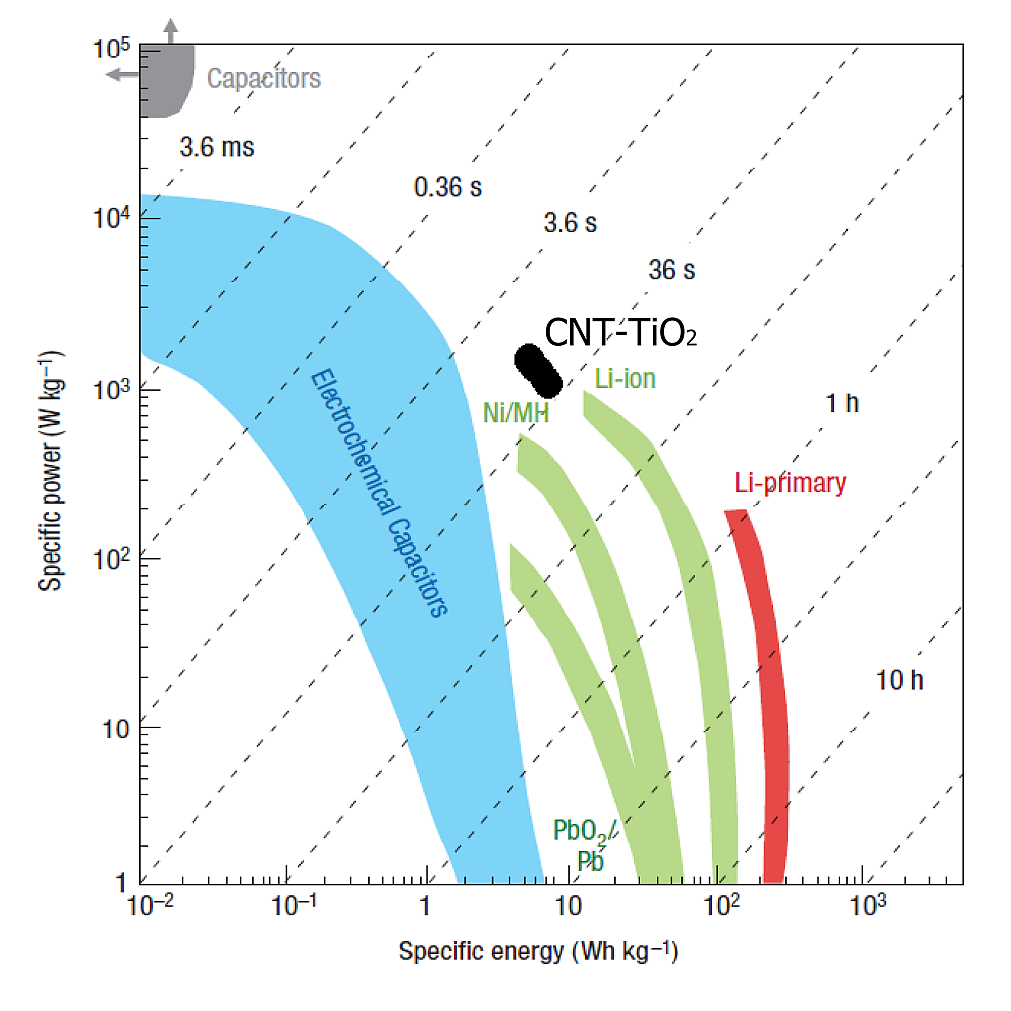
The performance of the CNT-TiO2 electrode can be compared to lithium-ion batteries and other electrochemical capacitors in the form of a ragone chart, shown in Figure 7. The storage capacity and the voltage range can be converted to energy density and power density with the formulas
The synergy between the two materials gives rise to high energy and good power. From the perspective of the high energy density Li-intercalation material, namely the TiO2 nanoparticles, the addition of carbon nanotubes led to a significant increase in power density.
IV. Conclusion
A supercapacitor electrode was fabricated from a nanocomposite consisting of multiwall carbon nanotubes and titanium oxide nanoparticles. Conventional electrochemical characterizations cyclic voltammetry and galvanostatic cycling gave a specific capacitance of 345 F/g at a current density of 0.1 A/g. New electrochemical characterization techniques derived from galvanostatic measurements allow one to obtain the peak capacitance associated with intercalation and to distinguish between electrostatic and faradaic contributions to the total charge stored. The new techniques show that most of the charge is stored faradaically, via the intercalation mechanism. The double layer charge storage mainly attributed to carbon nanotubes brought significant improvement in power density to the faradaic material. As a nanocomposite, CNT-TiO2 achieved a maximum energy density of 31 Wh/kg.
Acknowledgement
Helpful discussions from George Grüner, Bruce Dunn, Ryan Maloney, Veronica Augustyn as well as measurement support and TiO2 nanoparticles from Veronica and Jesse Ko are acknowledged and appreciated.
References
- (1) A.G. Pandolfo and A.F. Hollenkamp. J. Power Sources, 157:11, 2006.
- (2) G.A. Snook, P. Kao and A.S. Best. J. Power Sources, 196:1, 2011.
- (3) E. Frackowiak and F. Beguin. Carbon, 39:937, 2001.
- (4) L.L. Zhang and X.S. Zhao. Chem. Soc. Rev., 38:2520, 2009.
- (5) G. Grüner, G. Wee, M. Kaempgen, J. Ma and S.G. Mhaisalkar. Appl. Phys. Lett., 90:264104, 2007.
- (6) F. Wudl, I. Weitz, C. Liu, A.J. Bard and J.R. Heath. Electrochem. Solid-State Lett., 2:577, 1999.
- (7) J. Yeh, C. Du and N. Pan. Nanotechnology, 16:350, 2005.
- (8) M. Kaempgen, C.K. Chan, J. Ma, Y. Cui and G. Grüner. Nano Letters, 9:1872, 2009.
- (9) V. Bertagna, E. Frackowiak, K. Metenier and F. Béguin. Appl. Phys. Lett., 77:2421, 2000.
- (10) S. Delpeux V. Bertagna S. Bonnamy Frackowiak, K. Jurewicz and F. Béguin. Aip conference proceedings. volume 544, pages 533–536. AIP Publishing, 2000.
- (11) M. Meyyappan. J. Vac. Sci. Technol. A, 31:050803, 2013.
- (12) S. Biswas and L.T. Drzal. Chemistry of Materials, 22:5667, 2010.
- (13) Y. Huang, Y. Ma, C. Wang, M. Chen, Y. Wang, Z. Shi and Y. Chen. J. Phys. Chem. C, 113:13103, 2009.
- (14) M.R. Watt, R.A. Fisher and W.J. Ready. ECS J. Solid State Sci. Technol., 2:M3170, 2013.
- (15) B.E. Conway and W.G. Pell. J. Solid State Electrochem., 7:637, 2003.
- (16) D. Cericola and R. Kötz. Electrochim. Acta, 72:1, 2012.
- (17) J.P. Zheng. J. Electrochem. Soc., 150:A484, 2003.
- (18) P. Simon and Y. Gogotsi. Nat. Mater., 7:845, 2008.
- (19) Z.H. Wen, Q. Wang and J.H. Li. Adv. Funct. Mater., 16:2141, 2006.
- (20) J.N. Wu, G. Wang, Z.Y. Liu and Q. Lu. Mater. Lett., 71:120, 2012.
- (21) M.-L. Zhang, Y. Xue, Y. Chen and Y.-D. Yan. Mater. Lett., 62:3884, 2008.
- (22) E. Frackowiak, V. Khomenko, E. Raymundo-Piñero and F. Béguin. Appl. Phys. A, 82:567, 2006.
- (23) D. Weng, Q. Xiao, Y. Peng, X. Wang, H. Li, F. Wei Z. Chen, Y. Qin and Y. Lu. Adv. Funct. Mater., 19:3420, 2009.
- (24) T. Wang, A. Kiebele, J. Ma, S. Mhaisalkar and G. Grüner. J. Electrochem. Soc., 158:A1, 2011.
- (25) X.S. Zhao K. Zhang, L.L. Zhang and J. Wu. Chem. Mater., 22:1392, 2010.
- (26) B. Shao, Z. Fan, W. Qian, M. Zhang, J. Yan, T. Wei and F. Wei. Carbon, 48:487, 2010.
- (27) R. Hoch, D. Moy, C. Niu, E.K. Sichel and H. Tennent. Appl. Phys. Lett., 70:1480, 1997.
- (28) Y.S. Park, Y.C. Choi, S.M. Lee, D.C. Chung, D.J. Bae, S.C. Lim K.H. An, W.S. Kim and Y.H. Lee. Adv. Mater., 13:497, 2001.
- (29) J.M. Friedrich, D.V. Bavykin and F.C. Walsh. Adv. Mater., 18:2807, 2006.
- (30) S. Kerisit, K.M. Rosso D. Wang, J. Zhang, G. Graff, Z. Yang, D. Choi and J. Liu. J. Power Sources, 192:588, 2009.
- (31) J. Lim, J. Wang, J. Polleux and B. Dunn. J. Phys. Chem. C, 111:14925, 2007.
- (32) A.J. Bard and L.R. Faulkner. Electrochemical Methods: Fundamentals and Applications. Wiley, 2000.