Strongly coupled magnons and cavity microwave photons
Abstract
We realize a cavity magnon-microwave photon system in which magnetic dipole interaction mediates strong coupling between collective motion of large number of spins in a ferrimagnet and the microwave field in a three-dimensional cavity. By scaling down the cavity size and increasing number of spins, an ultrastrong coupling regime is achieved with a cooperativity reaching 12600. Interesting dynamic features including classical Rabi oscillation, magnetically induced transparency, and Purcell effect are demonstrated in this highly versatile platform, highlighting its great potential for coherent information processing.
pacs:
71.36.+c, 76.50.+g, 75.30.Ds, 42.50.PqIntroduction.— Systems with strong light-matter interaction have played crucial roles in quantum Kimble2008 ; Wallquist2009 and classical information processing Spreeuw1990 ; Aspelmeyer2013 as they enable coherent information transfer between distinct physical platforms. It is well known that systems with large electric dipole moment can couple strongly with the optical fields. However, the possibility of strong light-matter interaction via magnetic dipoles is mostly ignored. It is only recently that Imamoglu Imamoglu2009 has pointed out the direction to achieve strong light-matter interaction using collective excitations of spin ensembles, and visioned the promise of quantum information processing in these systems. Since then, various implementations have been proposed and experimentally investigated. Ensembles including ultracold atomic clouds Verdu2009PRL_atom , molecules Eddins2014PRL_Molecule , nitrogen vacancy centers in diamond ZhuNature2011 ; KuboPRL2010_CPW ; AmsussPRL2011 ; Kubo2011PRL_qubit ; Marcos2010PRL ; Ranjan2013PRL , and ion doped crystals SchusterPRL2010_Ruby ; Probst2013PRL_RE ; Tkalcec2014Arxiv_RE have been used to couple to microwave resonators or even superconducting qubits.
Magnetic materials provide a promising alternative to achieve strong light-matter interaction, because they have spin density many orders of magnitude higher than dilute spin ensembles investigated previously. For example, Soykal et al. Soykal2010_PRL ; Soykal2010PRB predicted that the nanomagnet-photon cavity can achieve strong light-matter interaction assisted by an extremely large number of spins in nanomagnets. In this Letter, we realize such a hybrid system which consists of a sphere of yttrium iron garnet (YIG, Y3Fe5O12) and a three-dimensional (3D) microwave cavity. This new system possesses several distinguishing advantages. Firstly, YIG has a high spin density () exceeding previous spin ensembles by orders of magnitudes. Secondly, spin excitations in single crystal and highly purified YIG possess very low damping rate. Thirdly, the spin-spin interactions through either exchange or dipolar interaction give rise to dispersions of spin excitations (defined modes) in YIG, which can be used for spatial multiplexing. It is also intriguing that there is nonlinear interaction between excitations in the YIG, which enable nonlinear amplification and control of magnons. For instance, Bose-Einstein condensates of quasi-equilibrium magnons have been realized at room temperature Demokritov2006_BEC .
With the proposed hybrid system, we experimentally demonstrate the coherent coupling between magnons (the collective spin excitation in YIG) and microwave photons. Because of the large spin number in YIG, strong coupling can be achieved. Experimental demonstration has been previously reported using a YIG thin film on a planar superconducting microwave cavity, and a high cooperativity of 1350 has been achieved Huebl2013PRL_YIG . Here, we show that by utilizing a spherical YIG geometry and 3D microwave cavity, our system obtains additional advantages such as higher quality () factors and more uniform coupling Paik2011PRL_3Dcavity ; Riste2013Nature_3Dcavity ; Kirchmair2013Nature_3Dcavity . Furthermore, our 3D system is highly tunable in various parameters, which allows us to observe characteristic phenomena associated with distinct parameter regimes, including the magnetically induced transparency (MIT, the magnetic analog of EIT, the electromagnetically induced transparency) and the Purcell effect. Moreover, by scaling the device dimensions, our 3D system can enter the so-called “ultra-strong coupling” (USC) regime, where the coupling rate reaches a large fraction of the oscillation frequency, sufficient to violate the rotating-wave approximation (RWA) Niemczyk2010 ; Fuchs09 ; Anappara2009_USC . Although these important features are measured in the classical regime, our results suggest important prospects of operating the coupled system in quantum regime at millikelvins where the ferromagnetic resonance (FMR) linewidth of YIG can go down to T Spencer1961PR_YIGLoss with magnon lifetime extended to as long as about 4 microseconds.
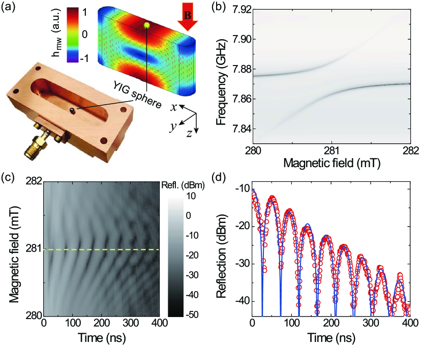
Experimental Setup.— The image of our device is shown in the bottom of Fig. 1(a), consisting of a 3D microwave cavity (only the bottom half is shown) and a highly polished YIG sphere which serves as the magnon cavity. The microwave cavity is a box machined from high conductivity copper to obtain high factor at room temperature. For example, the box with inner dimension of mm3 gives a TE101 mode at GHz with a linewidth of a few MHz. The simulated mode distribution (using COMSOL 3.5) of the cavity mode is given in the top of Fig. 1(a), where the arrows and colors indicate the magnetic field directions and their amplitudes. Spectroscopic measurement is carried out with a vector network analyzer (VNA) by probing the reflection of the microwave cavity through a coaxial cable antenna.
The YIG sphere is placed inside the microwave cavity and biased with a static magnetic field . The magnetic components of the microwave field perpendicular to the bias field induce the spin flip, and thus excite the magnon mode in YIG. Here, we are only interested in the lowest order FMR mode, which is a uniform collective mode that all the spins precess in phase. This mode has the highest coupling strength given that the microwave magnetic field around the YIG sphere is approximately uniform [Fig. 1(a)] as the wavelength with is the radius of the YIG sphere. The frequency of the uniform magnon mode linearly depends on the bias field where , with GHz/T is the gyromagnetic ratio and is determined by the anisotropy field. The bias magnetic field is tunable in the range of T, corresponding to a magnon frequency from few hundreds of MHz to about GHz.
Strong Coupling.— To study the microwave photon-magnon interaction, we adjust the bias field so that magnon is near-resonance with the cavity’s TE101 mode. The strongest coupling strength is obtained by placing the YIG sphere (0.36 mm in diameter) at the position with the maximum microwave magnetic field. The measured microwave reflection spectra with respect to the bias magnetic field is plotted in Fig. 1(b), which exhibits an avoided crossing at mT. The interaction between microwave photon and magnon can be described by the Hamiltonian with RWA:
| (1) |
where () is the creation (annihilation) operator for the microwave photon at frequency . For the magnon, the collective spin excitations are approximately represented by the Boson operator with Holstein–Primakoff approximation Holstein1940 . The coupling strength between the two systems is:
| (2) |
where is the resonance frequency and is the modal volume of the microwave cavity resonance, is the vacuum permeability, is the total number of spins, and is the spin number of the ground state Fe3+ ion in YIG. The coefficient describes the spatial overlap and polarization matching conditions between the microwave field and the magnon mode SM .
As shown in Fig. 1(b), the avoided crossing indicates the strong coupling between the microwave photon and the magnon, with the coupling strength . We can also extract the dissipation rates of both the microwave photon ( MHz) and the magnon ( MHz). The measured spectrum agrees well with the theoretical prediction of the reflection from the microwave cavity:
| (3) |
where is the external coupling to the cavity. For the coupled oscillator model described by the Hamiltonian in Eq. (1), hybridized photon-magnon quasi-particles appear for , with energies being . When the coupling strength exceeds the dissipation rates (), the system reaches the classical strong coupling regime. With the experiment parameters, we obtain a cooperativity of .
The strong coupling implies coherent dynamics between the photon and the magnon, such as Rabi oscillations. Hence, we investigated the temporary dynamics of photons in the strongly coupled system. Experimentally, by monitoring the time evolution of the cavity output after a short pulse excitation, we obtain the time traces that agree well with the theoretical prediction of Rabi oscillations [Fig. 1(c)]. The slight asymmetry about the bias magnetic field is due to the nonzero duration of the excitation pulse. Clearly, the cavity energy experiences periodic oscillation aside from the exponential decay, demonstrating the coherent energy exchange between photon and magnon. At mT where the magnon is on resonance with the microwave photon, we have the highest signal extinction, indicating complete energy exchange between the two systems. Also at this bias magnetic field, the oscillation period is the longest, corresponding to the narrowest gap () in the avoided crossing regime of the reflection spectrum. The time trace for mT is plotted in Fig. 1(d), showing a extinction ratio of more than 20 dB, and a period of ns which agrees well with the coupling strength ns. The calculated oscillation signal (solid line) using the coupling strength and the decay rate obtained from the frequency spectrum shows excellent agreement with the measured time trace (circles).
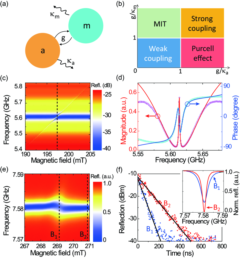
MIT and Purcell Effects.— Besides strong coupling, the tunability of our proposed system enables us to access other characteristic effects of the coherent photon-magnon interaction. Depending on the relative value of the coupling strength and the dissipation rates, there are different coupling regimes [Fig. 2(b)]. We will focus on coherent interactions with .
When the dissipation of the microwave cavity becomes dominant in the coupled system [Fig. 2(a), ], the avoided crossing feature in the measured spectrum will disappear. Indeed, as we tune the bias magnetic field, an MIT window passes through the broad microwave cavity resonance [Fig. 2(c)]. Depending on the detuning of the magnon frequency, the transparency window shows up as an asymmetric Fano-shape or symmetric peak. When the impedance matching [ in Eq. (3)] and on-resonance conditions are satisfied, the MIT window height is and linewidth is . When the magnon is tuned on resonance with the microwave photon [at mT, indicated by the dashed line in Fig. 2(c)], we have maximum extinction with a Lorentzian-shaped transparency window that replicates the magnon resonance [Fig. 2(d)]. The measured transparency window has a peak height of half unity with a maximum group delay of 110 ns. From the measured data, the corresponding dissipation rates and the coupling strength are fitted using Eq. (3) as MHz, MHz and MHz, corresponding to a cooperativity value of for this specific device configuration.
On the other hand, when the magnon decay dominates [Fig. 2(a), ], we enter the Purcell regime, with an enhanced decay of the microwave cavity photon due to its coupling to the lossy magnon. According to Eq. (3), the effective dissipation rate of the cavity is , enhanced by a Purcell factor () as a result of the photon-magnon interaction. Such linewidth broadening is confirmed by the measured reflection spectra at various bias magnetic fields [Fig. 2(e)]. Although the magnon resonance cannot be resolved due to its large linewidth, its magnetic dependence is inherited by the coupled mode and shows up as a small bend. For a clear comparison, the resonance spectra of the microwave cavity with (at mT) and without (at mT) the coupling to the magnon are plotted in the inset of Fig. 2(f). Due to the Purcell effect, the dissipation rate of the microwave resonance () increases from MHz to MHz, and the extinction ratio is reduced by 25%. Thus, we have and . From the experiment results, we can extract the coupling strength MHz and the magnon decay rate MHz that indeed fall inside the Purcell regime.
A more direct characterization of such Purcell effect is obtained by measuring the cavity photon lifetime. Since now the magnon dissipates very quickly, an accelerated exponential decay instead of a Rabi oscillation is expected after a pulsed excitation. The decay curves at bias magnetic fields and are plotted in Fig. 2(f), which gives a lifetime of ns and ns, respectively. These time domain measurements perfectly match the dissipation rates measured above in the frequency domain. Both the time and frequency domain measurements give a Purcell factor of about .
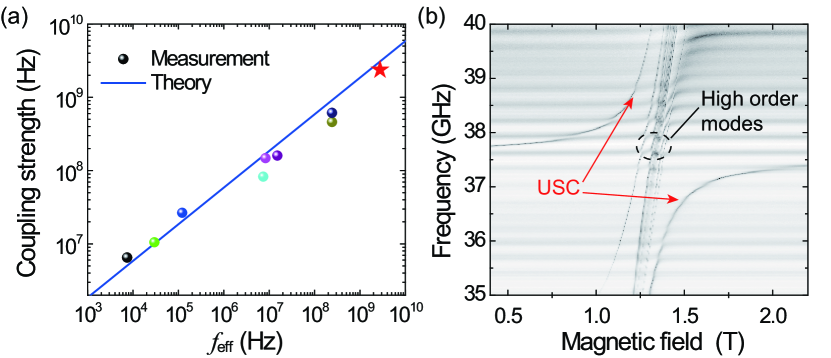
Ultrastrong Coupling.— Beyond the four coupling regimes discussed above determined by the ratio of coupling strength and dissipation rates, there exists a USC regime where the coupling strength becomes considerably comparable with the magnon frequency. In the USC regime, the RWA used in the Hamiltonian given by Eq. (1) is no longer valid. The USC has attracted intensive interests being a potential playground for ultra-fast coherent controlling and exploring new physics beyond RWA. It is notable that in our experiments by engineering the microwave cavity and the YIG sphere, we can tune the coupling strength and eventually extend our coupled system to the USC regime. From Eq. (2) we can see that the coupling strength , where is the volume of the YIG sphere which determines the spin number (). By increasing the resonance frequency and the YIG sphere size while reducing the microwave cavity size we can increase and consequently the coupling strength . The coupling strengths measured in nine devices of varying cavity and sphere dimensions are displayed in Fig. 3(a) as a function of . Good agreement is obtained in comparison with the theoretical prediction (solid line). During the experiments, different resonance frequencies ranging from the X band to the Ka band ( GHz to GHz) are tested, showing the great tunability of the magnon.
An ultra-strong coupling strength of GHz (represented by the star) has been achieved at a resonance frequency of GHz, where the microwave cavity size is dramatically reduced to mm3, and the YIG sphere diameter is increased to mm (corresponding to 3.5 spins). This coupled system yields a ratio of and reaches the USC regime. Figure 3(b) plots the reflection spectrum of the USC. Due to the large YIG sphere size which is now comparable with the microwave cavity, the microwave fields penetrating the YIG sphere is no longer as uniform and therefore excites non-uniform magnon modes, as labeled in Fig. 3(b). These non-uniform modes have higher frequency, and mostly couple weakly with the microwave cavity. Also at such high frequencies, the cavity resonance experiences higher losses. Nevertheless, due to the ultrahigh coupling rate, an ultra high cooperativity of is realized with the extracted dissipation rates of the microwave photon and the magnon resonance are MHz and MHz, respectively.
Conclusion.— We have experimentally realized coherent coupling between microwave photon and magnon at room temperature, and demonstrated the great potential of magnon as an information carrier. Strong coupling with high cooperativity has been achieved using spectroscopic measurement, and the coherent energy exchange has been illustrated with the Rabi oscillation measurement in the time domain. Both the MIT and Purcell effects have been observed, providing various possible applications for our proposed system. The coherent coupling can be further extended into the USC regime with a coupling strength of 2.5 GHz measured at 37.5 GHz carrier frequency, which is a new regime where the RWA approximation may be invalidated. Compared with previous systems, our system possesses a range of advantages thanks to the collective motion of large number of spins and uniform magnetic coupling. The excellent tunability properties of magnon system, together with its extended lifetime, reduced thermal excitation and the ability of coupling to microwave qubits, makes it a very promising candidate as a transducer that can interconnect different systems such as photonics, mechanics and microwave circuits.
Note added.—While we are preparing the manuscript, another interesting work by Tabuchi et al. on strongly coupled YIG-microwave cavity has appeared on arxiv Tabuchi2014 .
Acknowledgements.
This work is supported by DARPA/MTO MESO program. H. X. T. acknowledges support from a Packard Fellowship in Science and Engineering. LJ acknowledges support from the Alfred P Sloan Foundation, the Packard Foundation, and the DARPA Quiness program. The authors thank Dr. Michel H. Devoret for providing a prototype 3D microwave cavity.Appendix A Appendix A: Coupling strength and its dependence on the sphere location
The overlapping coefficient in Eq. (2) in the main text can be explicitly written as:
| (4) |
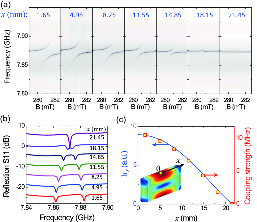
where is the maximum magnetic field intensity of the cavity mode, and is the magnetic field amplitude at the location of the YIG sphere, with are unit vectors and is along the bias field direction. In our experiment, the YIG sphere is attached to the cavity wall and moved only along the direction ( mm at the cavity boundary), as shown in the inset of Fig. 4(c). Due to the -dependent spatial distribution of the ac magnetic field within the microwave cavity, the coupling strength between the magnon and the microwave photon () can be adjusted by placing the YIG sphere at different position . In addition, the fields near the wall is polarized along -direction, thus we have
| (5) |
Figure 4(a) shows the reflection spectra at various position as a function of frequency and the bias magnetic field. The gap of the avoid crossing becomes smaller as we move the YIG sphere away from the magnetic field maximum (). The spectra at zero detuning magnetic field, where the magnon is on resonance with the microwave photon, is plotted in Fig. 4(b). From these spectra, the coupling strength is extracted as the half of the frequency split. Figure 4(c) shows the extracted coupling strength as a function of (red squares), and is in good agreement to the distribution of the microwave magnetic field (obtained by numerical simulation using COMSOL 3.5) according to Eq. (5) (solid blue line).
Appendix B Appendix B: Linewidth engineering
In order to reach different coupling regimes, the linewidths of both the microwave and the magnon cavities are adjusted. The highest quality () factors for both cavities are determined by the absorption of the material, thus it is impractical to further increase the them. To adjust the factor of the microwave resonance, we use a piece of microwave absorber to increase the absorption loss. To adjust the factor of the magnon, iron filings are glued on the YIG sphere surface to increase the absorption and scattering losses. In both cases, the factors can be varied from the intrinsic value (several thousands) to below 100, allowing us to explore different coupling regimes.
References
- (1) H. J. Kimble, Nature 453, 1023 (2008).
- (2) M. Wallquist, K. Hammerer, P. Rabl, M. Lukin, and P. Zoller, Phys. Scr. T137, 014001 (2009).
- (3) R. J. C. Spreeuw, N. J. van Druten, M. W. Beijersbergen, E. R. Eliel, and J. P. Woerdman, Phys. Rev. Lett. 65, 2642 (1990).
- (4) M. Aspelmeyer, T. J. Kippenberg, and F. Marquardt, arxiv:1303.0733 (2013).
- (5) A. Imamoglu, Phys. Rev. Lett. 102, 083602 (2009).
- (6) J. Verdú, H. Zoubi, C. Koller, J. Majer, H. Ritsch, and J. Schmiedmayer, Phys. Rev. Lett. 103, 043603 (2009).
- (7) A. W. Eddins, C. C. Beedle, D. N. Hendrickson, and J. R. Friedman, Phys. Rev. Lett. 112, 120501 (2014).
- (8) X. Zhu et al., Nature 478, 221 (2011).
- (9) Y. Kubo et al., Phys. Rev. Lett. 105, 140502 (2010).
- (10) R. Amsüss et al., Phys. Rev. Lett. 107, 060502 (2011).
- (11) Y. Kubo et al., Phys. Rev. Lett. 107, 220501 (2011).
- (12) D. Marcos, M. Wubs, J. M. Taylor, R. Aguado, M. D. Lukin, and A. S. Sø rensen, Phys. Rev. Lett. 105, 210501 (2010).
- (13) V. Ranjan et al., Phys. Rev. Lett. 110, 067004 (2013).
- (14) D. I. Schuster et al., Phys. Rev. Lett. 105, 140501 (2010).
- (15) S. Probst, H. Rotzinger, S. Wünsch, P. Jung, M. Jerger, M. Siegel, A. Ustinov, and P. Bushev, Phys. Rev. Lett. 110, 157001 (2013).
- (16) A. Tkalcec et al., arXiv:1402.5242v1 (2014).
- (17) O. O. Soykal and M. E. Flatté, Phys. Rev. Lett. 104, 077202 (2010).
- (18) O. O. Soykal and M. E. Flatté, Phys. Rev. B 82, 104413 (2010).
- (19) S. O. Demokritov, V. E. Demidov, O. Dzyapko, G. A. Melkov, A. A. Serga, B. Hillebrands, and A. N. Slavin, Nature 443, 430 (2006).
- (20) H. Huebl, C. W. Zollitsch, J. Lotze, F. Hocke, M. Greifenstein, A. Marx, R. Gross, and S. T. B. Goennenwein, Phys. Rev. Lett. 111, 127003 (2013).
- (21) H. Paik et al., Phys. Rev. Lett. 107, 240501 (2011).
- (22) D. Ristè et al., Nature 502, 350 (2013).
- (23) G. Kirchmair et al., Nature 495, 205 (2013).
- (24) T. Niemczyk et al., Nat. Phys. 6, 772 (2010).
- (25) G. D. Fuchs, V. V. Dobrovitski, D. M. Toyli, F. J. Heremans, and D. D. Awschalom, Science 326, 1520 (2009).
- (26) A. A. Anappara, S. De Liberato, A. Tredicucci, C. Ciuti, G. Biasiol, L. Sorba, and F. Beltram, Physical Review B 79, 201303 (2009).
- (27) E. G. Spencer, R. C. LeCraw, and R. C. Linares, Phys. Rev. 123, 1937 (1961).
- (28) T. Holstein and H. Primakoff, Phys. Rev. 58, 1098 (1940).
- (29) See Supplementary Material.
- (30) Y. Tabuch, S. Ishino, T. Ishikawa, R. Yamazaki, K. Usami, and Y. Nakamura, arxiv:1405.1913 (2014).