Breaking of symmetry in graphene growth on metal substrates
Abstract
In graphene growth, island symmetry can become lower than the intrinsic symmetries of both graphene and the substrate. First-principles calculations and Monte Carlo modeling explain the shapes observed in our experiments and earlier studies for various metal surface symmetries. For equilibrium shape, edge energy variations manifest in distorted hexagons with different ground-state edge structures. In growth or nucleation, energy variation enters exponentially as , strongly amplifying the symmetry breaking, up to completely changing the shapes to triangular, ribbon-like, or rhombic.
While exfoliation techniques can produce monolayers of graphene 2004novoselovelectric and other two-dimensional (2D) materials 2011colemantwodimensional of extraordinary quality 2008bolotinultrahigh , their lack of scalability hampers their use in applications. Chemical vapor deposition (CVD) synthesis 2014tetlowgrowthof can address the scalability concern. However it is difficult to produce graphene samples of quality comparable to exfoliated layers 2014yazyevpolycrystalline , motivating both empirical and theoretical effort to understand and improve graphene growth.
Because CVD involves a solid substrate in contact with graphene, their interaction alters the latter’s properties. This influence cannot be described simply as the interaction of complete graphene crystal with the support. Instead, the relevant processes occur as graphene assembles. Due to the inherent difficulty of observing growth in situ, theoretical understanding is indispensable.
Previous study of the morphology of graphene under kinetic or thermodynamic control from atomistic level 2012artyukhovequilibrium was able to predict many observed shapes such as zigzag-edged (slowest-growing) hexagons 2011yucontrol ; 2012genguniform ; 2013haotherole or dodecagons with (fastest-etching) 2013maedgecontrolled and (equilibrium shape) angles 2014chennearequilibrium . All these shapes inherit the hexagonal symmetry of graphene. Yet, recurring observations of less symmetric shapes call for a deeper study of the effects of the substrate on the growth of graphene. In this work we reveal how symmetry breaking manifests in graphene growth and results in shapes with lowered (threefold, twofold) symmetry, using Ni and Cu substrates as examples. For the equilibrium shape of graphene on the Ni(111) surface, we show using first principles calculations how tangential ‘sliding’ breaks inversion symmetry and leads to different atomistic structures at opposite edges of graphene islands, yet the effect on the Wulff shape is rather weak. However, since the growth rates contain the energy terms affected by symmetry in the exponent, we find that under kinetic control, the asymmetry is amplified, causing a qualitative transition from hexagonal (equilibrium) to triangular (growth) shapes. Nucleation statistics, also exponential in the symmetry-breaking strength, can cause strong selection of just one of the two near-degenerate stacking ‘phases’ of graphene. Casting the atomistic insight into a coarse-grained Monte Carlo (MC) model of growth, we explain our observations of broken-symmetry islands on different surfaces of polycrystalline Cu foil.
Typically, graphene is incommensurate with substrates used for CVD growth. Without translational invariance even the most basic concepts such as interface energy and Wulff construction cease to be a reliable foothold. Therefore we first focus on the important special case of Ni(111) substrate (with Co(0001) being essentially analogous) where graphene can stretch by ~1% to accommodate the lattice constant of metal surface, resulting in perfect epitaxial matching. Since both the (111) surface and graphene have a sixfold rotation axis, it is possible to form an interface that preserves this symmetry. However it turns out to be unstable with respect to tangential displacements that break the alignment of the axes producing other stacking phases which reduce the symmetry to threefold (or even twofold). Typically one sublattice of carbon atoms is on top of upper-layer Ni atoms, and the other either in fcc of hcp sites of the Ni lattice, forming two almost-degenerate structures (Fig. 1) that differ only in positioning with respect to the 2nd layer of Ni. Either way the overall symmetry is triangular rather than hexagonal and graphene sublattices become inequivalent—like in BN 2011liubnwhite . In particular, the six previously degenerate Z edges split up into two triplets, denoted as ‘’ and ‘’.
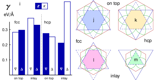
We begin with determining the substrate effect on the equilibrium shape of graphene on Ni(111). The edge energy for arbitrary orientation can be expressed analytically from basic armchair (A) and zigzag (Z) edge energies 2010liugraphene , accounting for inequivalent Z edges: . Here is the angle with respect to the closest direction, when mod , and otherwise. Since the A edge symmetry is not broken by the substrate, is known from previous work 2012artyukhovequilibrium , leaving us with just the two zigzag edge energies and to compute. As a consequence of inversion symmetry breaking, not only the energies of and edges can be different, but the edges can have different ground-state atomistic structures. Using density functional theory computations 1993kresseabinitio ; *1996kresseefficient; 1994blochlprojector ; *1999kressefromultrasoft; 1980ceperleygroundstate ; 1996perdewgeneralized ; *1997perdewgeneralized (details in Supplemental Material 111See Supplemental Material at http://prl.aps.org for for details of computations and edge energy fitting.), we screened a total of 12 possible combinations: 2 for stacking (fcc, hcp) × 2 for direction () × 3 structures (conventional hexagonal zigzag, Z; Klein, K 1994kleingraphitic ; pentagon-reconstructed Klein—e.g. 2013wagnerstablehydrogenated ). The pentagon–Klein reconstruction is always unfavorable. For both stackings, one of the ground-state edge structures is Z but the opposite side favors K (fcc: , hcp: ) as top C atoms cannot form in-plane bonds with Ni atoms and prefer to be three-coordinated. To determine edge energies in the absence of inversion symmetry, we used a series of increasingly larger triangular islands with only or only edges 2011liubnwhite , by fitting their energies as where is the number of atoms Note1 . We considered two scenarios, with graphene flakes on top of the Ni(111) surface or inlaid in the topmost Ni plane 2013paterainsitu . In all cases (Fig. 1i) the energies of and edges are close, except for the inlay-hcp case where the direction is impossible to interface with the Ni lattice without a large geometrical strain (hence the outstandingly high value).
By plotting in polar coordinates 1951herringsometheorems (green line in Fig. 1 (j–m)) we obtain the Wulff construction. We find that the equilibrium shapes are truncated triangles (lowered-symmetry hexagons), except for the case of inlay-hcp stacking. Truncated shapes were indeed observed on Ni(111) while this manuscript was in preparation 2014garcia-lekuespindependent , and according to our calculations these islands should have Klein edges in three out of six directions. Yet multiple other observations show sharp-cornered triangles on top of metal surface 2012olleyieldand ; 2013paterainsitu , impossible to explain thermodynamically (Fig. 1). This compels us to investigate growth kinetics.
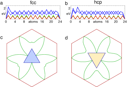
Our “nanoreactor” model of graphene growth 2012artyukhovequilibrium is naturally extendable to the case of inversion-inequivalent zigzag edges. We consider only the ground-state edge structures in the on-top scenario. Carbon atoms are added sequentially to the edges (Fig. S1 Note1 ) obtaining the free energy sequences shown in Fig. 2 for (a) fcc and (b) hcp stacking. The familiar ‘nucleation–kink flow’ picture is clearly observed in this plot 2012artyukhovequilibrium . In either stacking, the hexagonal Z edge (blue solid line) has a higher free energy barrier for the formation of a new atomic row than K (blue dashed line): 2.24 vs. 1.49 eV for fcc and 2.20 vs. 1.633 eV for hcp (difference eV). And because the rate of formation of new atomic rows at the edge depends on these energy barriers exponentially, K edges will grow much faster than Z and disappear from the growth shape. The closed-form expression for graphene edge growth velocity 2012artyukhovequilibrium can be used (with appropriate modifications to account for broken symmetry) to plot the kinematic Wulff constructions. As seen in Fig. 2 (c,d), the result is a triangle with Z edges, for fcc stacking and for hcp.
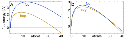
The essentially equal values of rate-limiting barriers for the hcp and fcc stackings predict similar growth rates. However, to assess their relative abundance one also needs to consider nucleation 2014artyukhovwhynanotubes . Based on the edge energies and difference between fcc and hcp 2D bulk energies ( eV/atom from the computations) the free energy of an island can be expressed as a function of its area (number of atoms), , where is the 2D ‘bulk’ energy of the respective graphene phase, is the chemical potential, is the edge energy, and is a form factor to discriminate between triangles and hexagons (which we approximate as perfect). Fig. 3 shows free energy plots for the two ‘phases’ at a chemical potential bias of eV for the (a) inlay and (b) on-top scenarios. In the former scenario (a), despite the triangular shape of hcp domains, low edge energy yields a much lower nucleation barrier—by 1.54 eV in this example. This leads to a nucleation rate difference in favor of the higher-energy hcp phase. Here again exponentiation greatly amplifies the symmetry-breaking effect (compared to the ratio of which is only ). While the growth shapes of the two phases are oppositely oriented (Fig. 2 (c,d)), selective nucleation eliminates one of the two possibilities. This explains the recent observations of co-oriented graphene triangles on Ni(111) 2013liequilibrium .
In contrast, for graphene islands on top of the surface the nucleation barrier difference is merely on the order of (b), implying weak if any selectivity (the hcp–fcc preference is reversed around eV). Indeed, both phases were identified via characteristic ‘translational grain boundary’ defects 2010lahirianextended and by direct observations 2014bianchiniatomicscale .
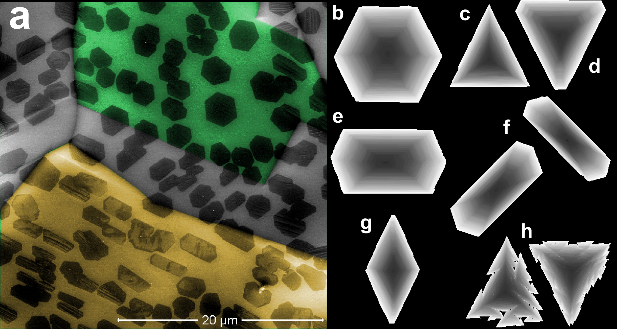
While Ni(111) provides a convenient system for atomistic analysis, symmetry-breaking effects are equally important for other substrates without perfect epitaxy with graphene, the foremost being copper. Fig. 4 (a) presents a scanning electron microscope image of graphene islands on a Cu foil. The growth was carried out in a tube furnace CVD system, similar to previous work 2013haotherole . For this sample we used an oxygen-free Cu substrate with 0.1 torr H2 pressure and torr methane pressure. The growth temperature was 1035 °C and the growth time was 20 min. Several Cu grains are seen, with many graphene islands (dark) on each. Even though all graphene islands grew simultaneously at the same conditions, we see two distinct shape classes. Nearly all islands are hexagonal, but some are almost perfect while others are elongated. All islands on a single Cu grain belong to the same class (except for cases with several islands colliding within the same grain or across the boundaries 222After a collision within the same Cu grain the shape of composite island will approach the original kinematic Wulff construction as it grows larger compared to the separation between the original two. Thus one could still grow large single-crystals with well-defined shape even starting from more than one nucleus.). Furthermore, graphene islands on each grain are aligned, which is especially noticeable for elongated islands. The density of islands and their size is similar between the grains. This suggests that the basic underlying mechanisms in their growth are the same, and the shape difference is determined by subtle differences between crystallographic surfaces of Cu. Indeed, electron back-scatter diffraction studies established that hexagonal domains form on Cu(111), while elongated domains grow on Cu (100) or (110) 2013haotherole ; 2013murdockcontrolling .
To understand the shapes in Fig. 4 (a) we consider the symmetry of the graphene+Cu system. Though the (111) surface is triangular, translational incommensurability of the lattices means that a growing edge will have a different positioning with respect to the underlying Cu atoms at different times, and on average, the symmetry-breaking effects will compensate. Interestingly, this precludes the sliding mode of symmetry breaking (as in Ni(111)) and restores the symmetry for the composite system. For rectangular (110) and square (100) surfaces, two parallel graphene edges should align with one of the orthogonal basic crystallographic directions of the surface, but the other four edges will remain misaligned with the substrate. Thus the six edges will be split in two sets of two and four (unlike three and three on Ni). During kink-flow growth, incommensurability of edges with the underlying substrate will again be averaged out, but this time the averaging will differ between the families. Again, the rotational symmetry of graphene islands is reduced to the common divisor of 6 and 2 or 4, respectively, i.e., .
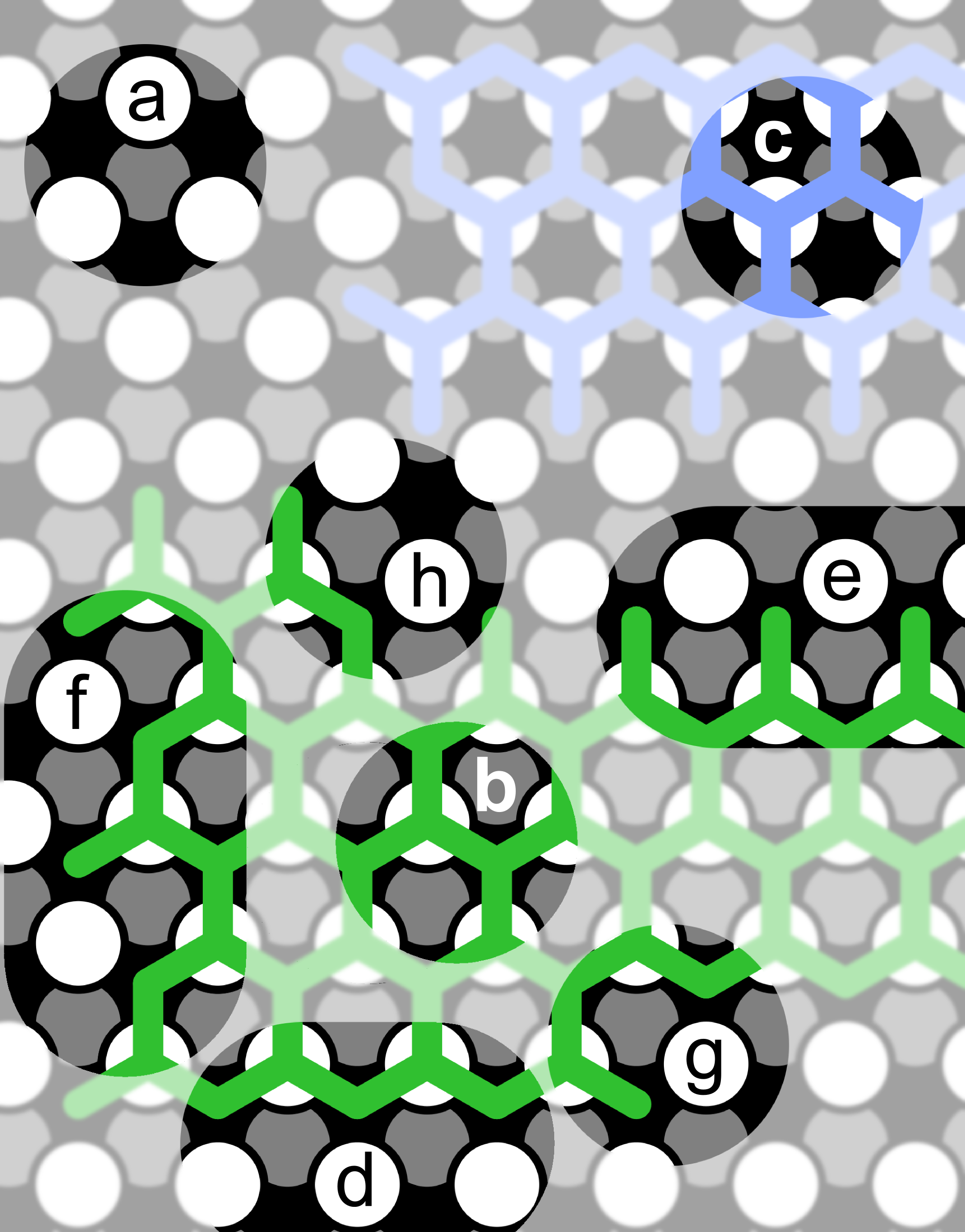
Building on the understanding of how the substrate modulates the growth velocities in different directions one can model this and other possibilities using coarse-grained MC simulation as follows. Graphene is represented by a triangular lattice (nodes are hexagon centers), starting with a single occupied point. At each time step, all vacant cells with occupied neighbors are classified either as Z sites (three occupied neighbors along a straight line) or k (kink; armchair edge is an ‘array of kinks’ 2009dingdislocation ). The relative probability of addition to a Z site (nucleation of a new atomic row, in the atomistic calculations) is the input parameter. Probabilities of all sites form a distribution which is sampled to determine the next site to be occupied, and the process is iterated. As a result we obtain the shape in Fig. 4 (b), which is the familiar graphene hexagon frequently observed on Cu(111) 2011yucontrol ; 2013haotherole , liquid Cu 2012genguniform , and in Fig. 4 (a), in agreement with the nanoreactor model predictions for isotropic substrates 2012artyukhovequilibrium .
Recalling our analysis of growth kinetics on Ni (Fig. 2), the essential physical insight that explains triangular growth shapes is the difference between probabilities to initiate a new row on Z vs. K edges. Our MC model can naturally capture this with two independent parameters for two inequivalent crystallographic orientations of Z edges, and . Fig. 4 (c) shows the sharp triangle from a run with , corresponding to our first-principles results for . Only edges are present, and it is in perfect agreement with the analytical kinematic Wulff shape of Fig. 1. Fig. 4 (d) shows the truncated triangle produced in a run with , barely showing any edge fragments. Thus, six-sided shapes are only possible when the growth barrier difference is small, , or no more than 0.2 eV for typical graphene CVD conditions, which is a rather close coincidence.
For rectangular surfaces such as Cu(110) or Ge(110) 2014leewaferscale , or twofold-symmetric stackings on Ni(111), two input probabilities are again needed, now for the two ‘horizontal’ and four ‘diagonal’ directions, and . Typically one would expect the edges that are aligned with close-packed surface ‘grooves’ to grow slower, resulting in . This produces elongated shapes such as Fig. 4 (e), closely resembling the high aspect ratio islands in Fig. 4 (a). Cu(100) is similar, but there are now two orthogonal close-packed directions for long graphene edges to align with. This will produce two rather than one preferred alignments at a 90°angle with each other within the same Cu grain (Fig. 4 (f)) as observed experimentally 2013murdockcontrolling ; 2011ogawadomainstructure . Finally, if , the shape shown in Fig. 4 (g) results.
It is remarkable how a simple MC model informed by atomistics allows a unified description of Ni(111), all surfaces of Cu (including liquid), and pretty much any metal surface without an epitaxial match with graphene just based on its symmetry. It can similarly be applied to model any other graphene-like material with inequivalent sublattices, such as BN 2012ismachtowardthe ; 2012kimsynthesis or transition metal dichalcogenides. By the same token, growth units larger than hexagons 2013dongkinetics can be treated. Going even further one can emulate diffusion in this model. This is achieved by making the growth probabilities depend not only on site type, but also on the number of unoccupied cells within some distance. Edges of protrusions have better access to feedstock supply at the free catalyst surface, producing diffusion instabilities. This refinement reproduces sawtooth patterns seen on the edges of metal chalcogenide islands 2013vanderzandegrainsand ; 2013zhangcontrolled with a characteristic dendritic but not finger-like morphology (Fig. 4 (h)), reminiscent of the Sierpinski fractal.
In summary, the symmetry of emergent carbon islands reflects not the symmetry of graphene per se but rather the combined symmetry of its stacking on a substrate surface, which generally is lower than either graphene (hexagonal) or the surface (hexagonal, square, rectangular…). On epitaxially matched surfaces such as Ni(111) or Co(0001) the symmetry breaking effect is particularly apparent at the edges, resulting in different ground-state structures (Z vs. Klein) for different directions (), and causing equilibrium shapes with a (typically, mild) violation of inversion symmetry. However, in kinetics, the symmetry-lowering interactions become exponentially amplified as , and Klein edges grow much faster than Z, resulting in triangular growth shapes with only Z edges. Similarly, exponentiation can make symmetry effects strongly pronounced in nucleation, so that edge energy differences can play a decisive role in selection of the graphene–Ni(111) stacking. We apply this insight to growth on Cu, where different graphene island morphologies are concurrently observed on different crystalline grains of the same foil, using a Monte Carlo growth model that draws upon our Ni(111) analysis but can be tuned to any substrate symmetry, commensurate or incommensurate with graphene, crystalline or liquid. Since crystal symmetry of the substrate dictates both the shape of islands and their alignment, single-crystalline substrates offer better control over both the morphology of graphene islands and grain boundaries in the resulting films. This improved understanding of the role of substrate symmetry in graphene growth is crucial for improving the quality 2014tetlowgrowthof or engineering grain boundaries 2014yazyevpolycrystalline in CVD graphene.
References
- (1) K. S. Novoselov et al., Science 306, 666 (2004).
- (2) J. Coleman et al., Science 331, 568 (2011).
- (3) K. Bolotin et al., Solid State Commun. 146, 351 (2008).
- (4) H. Tetlow et al., Phys. Rep. 542, 195 (2014).
- (5) O. V. Yazyev and Y. P. Chen, Nat. Nanotech. (2014).
- (6) V. I. Artyukhov, Y. Liu, and B. I. Yakobson, Proc. Natl. Acad. Sci. U.S.A. 109, 15136 (2012).
- (7) Q. Yu et al., Nat. Mater. 10, 443 (2011).
- (8) D. Geng et al., Proc. Natl. Acad. Sci. U.S.A. 109, 7992 (2012).
- (9) Y. Hao et al., Science 342, 720 (2013).
- (10) T. Ma et al., Proc. Natl. Acad. Sci. U.S.A. 110, 20386 (2013).
- (11) J. Chen et al., Adv. Mater. 26, 1348 (2014).
- (12) Y. Liu, S. Bhowmick, and B. I. Yakobson, Nano Lett. 11, 3113 (2011).
- (13) Y. Liu, A. Dobrinsky, and B. I. Yakobson, Phys. Rev. Lett. 105, 235502 (2010).
- (14) G. Kresse and J. Hafner, Phys. Rev. B 47, 558 (1993).
- (15) G. Kresse and J. Furthmüller, Phys. Rev. B 54, 11169 (1996).
- (16) P. E. Blöchl, Phys. Rev. B 50, 17953 (1994).
- (17) G. Kresse and D. Joubert, Phys. Rev. B 59, 1758 (1999).
- (18) D. M. Ceperley and B. J. Alder, Phys. Rev. Lett. 45, 566 (1980).
- (19) J. P. Perdew, K. Burke, and M. Ernzerhof, Phys. Rev. Lett. 77, 3865 (1996).
- (20) J. P. Perdew, K. Burke, and M. Ernzerhof, Phys. Rev. Lett. 78, 1396 (1997).
- (21) See Supplemental Material at http://prl.aps.org for for details of computations and edge energy fitting.
- (22) D. Klein, Chem. Phys. Lett. 217, 261 (1994).
- (23) P. Wagner et al., Phys. Rev. B 88, 094106 (2013).
- (24) L. L. Patera et al., ACS Nano 7, 7901 (2013).
- (25) C. Herring, Phys. Rev. 82, 87 (1951).
- (26) A. Garcia-Lekue et al., Phys. Rev. Lett. 112, 066802 (2014).
- (27) M. Olle, G. Ceballos, D. Serrate, and P. Gambardella, Nano Lett. 12, 4431 (2012).
- (28) V. I. Artyukhov, E. S. Penev, and B. I. Yakobson, Nat. Commun. 5, 4892 (2014).
- (29) M. Li et al., Phys. Rev. B 88, 041402 (2013).
- (30) J. Lahiri, Y. Lin, P. Bozkurt, I. Oleynik, and M. Batzill, Nat. Nanotech. 5, 326 (2010).
- (31) F. Bianchini, L. L. Patera, M. Peressi, C. Africh, and G. Comelli, J. Phys. Chem. Lett. , 467 (2014).
- (32) After a collision within the same Cu grain the shape of composite island will approach the original kinematic Wulff construction as it grows larger compared to the separation between the original two. Thus one could still grow large single-crystals with well-defined shape even starting from more than one nucleus.
- (33) A. T. Murdock et al., ACS Nano 7, 1351 (2013).
- (34) F. Ding, A. R. Harutyunyan, and B. I. Yakobson, Proc. Natl. Acad. Sci. U.S.A. 106, 2506 (2009).
- (35) J.-H. Lee et al., Science 344, 286 (2014).
- (36) Y. Ogawa et al., J. Phys. Chem. Lett. 3, 219 (2011).
- (37) A. Ismach et al., ACS Nano 6, 6378 (2012).
- (38) K. K. Kim et al., Nano Lett. 12, 161 (2012).
- (39) G. Dong and J. W. M. Frenken, ACS Nano 7, 7028 (2013).
- (40) A. M. van der Zande et al., Nat. Mater. 12, 554 (2013).
- (41) Y. Zhang et al., ACS Nano 7, 8963 (2013).