Symbol-Based Successive Cancellation List Decoder for Polar Codes
Abstract
Polar codes is promising because they can provably achieve the channel capacity while having an explicit construction method. Lots of work have been done for the bit-based decoding algorithm for polar codes. In this paper, generalized symbol-based successive cancellation (SC) and SC list decoding algorithms are discussed. A symbol-based recursive channel combination relationship is proposed to calculate the symbol-based channel transition probability. This proposed method needs less additions than the maximum-likelihood decoder used by the existing symbol-based polar decoding algorithm. In addition, a two-stage list pruning network is proposed to simplify the list pruning network for the symbol-based SC list decoding algorithm.
Index Terms:
Error control codes, polar codes, successive cancellation decoding, list decodingI Introduction
Since polar codes were introduced by Arikan [1], they have attracted lots of interest in the fields of communication and coding theory, because they can provably achieve the channel capacity not only for arbitrary discrete memoryless channels, but also for any continuous memoryless channel [2]. However, their capacity approaching can be achieved only when the code length is large enough ( [3]) under the SC decoding algorithm. For short or moderate code length, in terms of the error performance, polar codes with the SC decoding algorithm is worse than turbo codes or low-density parity-check codes [4, 5].
To improve the error performance of polar codes, lots of work have been done. Systematic polar codes [6] was proposed to reduce the bit error rate while guaranteeing the same frame error rate (FER) compared with their non-systematic counterparts. An SC list decoding algorithm for polar codes was proposed in [7]. The SC list decoding algorithm outperforms the SC decoding algorithm and achieves the error performance close to that of the ML decoding algorithm at the cost of complexity of , where is the list size. Moreover, the concatenation of polar codes with cyclic redundancy check (CRC) codes was introduced in [4, 8]. To decode the CRC-concatenated polar codes, a CRC detector is used in the SCL decoding algorithm to help the codeword determination. The combination of an SCL decoding algorithm and a CRC detector is called CRC-aided SCL (CA-SCL) decoding algorithm. [8] shows that with the CA-SCL decoding algorithm, the error performance of a (2048, 1024) CRC-concatenated polar code is better that of a (2304, 1152) LDPC code, which is used in the WiMax standard [9].
To implement decoders for polar codes, several works have been done for the SC decoding algorithm. Arikan [1] showed that a fully parallel SC decoder has a latency of clock cycles. This decoder has complexity of . A tree SC decoder and a line SC decoder with complexity of were proposed in [10]. These two decoders have the same latency as the fully parallel SC decoder. To reduce complexity further, Leroux [3] proposed a semi-parallel SC decoder for polar codes by taking advantage of the recursive structure of polar codes to reuse processing resources. To reduce the latency, a simplified SC (SSC) polar decoder was introduced in [11] and it was further analyzed in [12]. In the SSC polar decoder, a polar code is converted to a binary tree including three types of nodes: rate-one, rate-zero and rate- nodes. Based on the SSC polar decoder, the ML SSC decoder makes use of the ML decoding algorithm to deal with rate- nodes in [13, 14]. However, SSC and ML-SSC polar decoders depend on positions of information bits and frozen bits, and are code-specific consequently. In [15], a pre-computation look-ahead technique was proposed to help the tree SC decoder shorten the latency by half. An efficient SCL decoder architecture was proposed in[16]. Recently, parallel decoders of polar codes were proposed in[17]. To avoid ambiguity between the aforementioned fully parallel SC decoder in [1] and parallel decoders in [17], we call the latter as symbol-based polar decoders in this paper because an -bit symbol-based polar decoder decodes bits at a time instead of only one bit. However, [17] is focused on some specific case and does not provide a general discussion. Meanwhile, it uses the ML decoder to calculate the symbol-based channel transition probability, which is not complexity-efficient enough.
The main contributions of this paper are:
-
•
Generalized symbol-based polar decoding algorithms are discussed. Furthermore, a symbol-based recursive channel combination relationship is derived to calculate the symbol-based channel transition probability. The proposed method needs less additions than the ML detector used in [17].
-
•
An -bit symbol-based SCL polar decoder needs to find most-reliable lists among list candidates. A two-stage list pruning network are proposed to perform this list pruning function. list candidates are divided into groups. Each group has list candidates. In the first stage, most-reliable lists for each group are found. Then, most-reliable list candidates are sorted out from list candidates generated by the first stage. If , the two-stage list pruning network can achieve lower complexity and a shorter critical path delay than the list pruning network with .
The rest of our paper is organized as follows. Section II briefly reviews polar codes and existing decoding algorithms. In Section III, the generalized -bit symbol-based SC and SCL decoding algorithms for polar codes are discussed. Based on the Arikan’s recursive channel transformations, we derive the symbol-based recursive channel combination relationship to calculate the symbol-based channel transition probability. To simplify the selection of the list candidates, a two-stage list pruning network is proposed in Section IV. Some conclusions are given in Section V.
II Polar Codes and Existing Decoding Algorithms
II-A Polar Codes
Polar codes are linear block codes. The block length of polar codes is restricted to a power of two, for . We follow the notation for vectors in [1], namely . Assume is the encoding bit sequence. Let . The corresponding encoded bit sequence is generated by
| (1) |
where is an bit-reversal permutation matrix and denotes the -th Kronecker power of .
For any index set , let denote the sub-sequence of defined by . Denote the complement of in as . Let . For an polar code, the encoding bit sequence is grouped into two parts: a -element part which carries information bits, and whose elements are predefined frozen bits. For the sake of convenience, frozen bits are set to be zero.
II-B SC Decoding Algorithm for Polar Codes
Given a transmitted codeword and the corresponding received word , the SC decoding algorithm for an polar code decodes the encoding bit sequence from to successively one by one as shown in Alg. 1. Here, represents the estimated value for . is the probability that is received and the previously decoded bits are given is zero or one.
To calculate , the following Arikan’s recursive channel transformations [1] are used:
| (2) |
and
| (3) |
where , and .
II-C SCL Decoding Algorithm for Polar Codes
Instead of making decision for each information bit of in an SC decoding algorithm, the SCL decoding algorithm [7] creates two paths in which the bit is assumed to be 0 and 1, respectively. If the number of paths is greater than the list size , the most-reliable paths are selected out. At the end of the decoding procedure, the most reliable path is chosen as . The SCL decoding algorithm is described in Alg. 2. Without loss of generality, assume to be a power of two, i.e. . Let represent the -th list vector, where .
Here, S is a structure type array with the size of . Each element of S has three members: P, L, and U. The function sortPDecrement sorts the array S by the decreasing order of P.
II-D CA-SCL Decoding Algorithm for Polar Codes
The CA-SCL decoding algorithm is used for the CRC-concatenated polar codes. The difference between the CA-SCL [8] and the SCL decoding algorithms is how to make the final decision for . If there is at least one path satisfying the CRC constraint, the most-reliable CRC-valid path is chosen for . Otherwise, the decision rule of the SCL decoding algorithm is used for the CA-SCL decoding algorithm. Since now, without being specified, polar codes mentioned in the following sections are CRC-concatenated polar codes.
III -bit Symbol-based Decoding Algorithm for Polar Codes
III-A Generalized Symbol-based SC Decoding Algorithm for Polar Codes
In [17], only two-bit, four-bit, eight-bit symbol-based decoding algorithm for polar codes are discussed. Here, a generalized -bit symbol-based decoding algorithm for polar codes is discussed. Without loss of generality, assume is a power of two, i.e. . Define , for . and are defined as:
| (4) |
Then the decision rule of the -bit symbol-based SC decoding algorithm can be described as,
| (5) |
where represents the cardinality of . If , this decoding algorithm is a maximum-likelihood sequence decoding algorithm.
If all bits of are independent and each bit has an equal probability of being a 0 or 1, the following symbol-based recursive channel combination relationship can be used to calculate the symbol-based channel transition probability :
Proposition 1.
For any , , , , assume and , then
| (6) |
Proof.
According to Bayes’ theorem,
| (7) |
Because all bits of are independent and each bit has an equal probability of being a 0 or 1,
Therefore,
| (8) |
According to Eq. (3),
| (9) |
Similar to the SC decoding algorithm, an -bit symbol-based SC decoding algorithm can be represented by using a message flow graph (MFG) as well, where a channel transition probability is referred as a message for the sake of convenience. If the code length of a polar code is , the MFG can be divided into stages : one initial stage and calculation stages. For the SC decoding algorithm, all calculation stages carry out the calculation of Eq. (2) and (3). However, for the -bit symbol-based SC decoding algorithm, the Arikan’s recursive transformations are performed in the first calculation stages, called channel transformation stages. In the last calculation stages, called channel combination stages, Eq. (6) is used to compute messages. Therefore, an -bit symbol-based SC decoding algorithm contains two parts. The first part contains calculations of the first stages and consists of SC decoders for polar codes of length . These SC decoders are called as component decoders. There are no message exchange between these component decoders. Channel combination stages use outputs of channel transformation stages to calculate symbol-based messages and feed the estimated symbol back to component decoders to update partial-sums.
For example, as shown inFig. 1, the MFG of a four-bit symbol-based SC decoding algorithm for a polar code with has four stages. Messages of the initial stage (S0) come from the channel directly. Messages of the first stage (S1) are calculated with Arikan’s recursive transformations. Messages of the second and third stages (S2 and S3) are calculated with Eq. (6). The four small gray boxes on the right are four component SC decoders. And stages in the big gray box on the left are channel combination stages. Here,
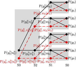
We can take advantage of the symbol-based channel combination to reduce complexity of calculating the symbol-based channel transition probability. In [17], an ML decoder is use to calculate the symbol-based message of stage from output of component decoders directly. There are possible values for an -bit symbol. [13] shows that additions are needed to calculate the log-likelihood (LL) message corresponding to each value. Therefore, an ML decoder needs additions in total. In channel combination stages, there are nodes in the -th stage and each node contains messages. One addition is needed to compute each LL message according to Eq. (6). Hence, channel combination stages need additions in total. For the example shown in Fig. 1, the ML decoder needs additions. The channel combination stages need only additions, which is only a half of those needed by the ML decoder.
In terms of the error performance, simulations of [17] show that there is no observed performance loss for the the -bit symbol-based SC decoding algorithm using the ML decoder to calculate the symbol-based message, compared with the SC polar decoding algorithm. Since our channel combination relationship can be used to provide the same calculation results as the ML decoder used in [17] does, the -bit symbol-based SC decoding algorithm using the symbol-based channel combination relationship does not have any observed performance degradation compared with the SC decoding algorithm.
III-B Generalized Symbol-based SCL Decoding Algorithm for Polar Codes
The symbol-based SCL decoding algorithm is more complex than the SCL algorithm, since the path expansion coefficient is not a constant any more. In the SCL algorithm, for each information bit, the path expansion coefficient is two. But for the -bit symbol-based SCL decoding algorithm, the path expansion coefficient is , which depends on the number of information bits in an -bit symbol. The -bit symbol-based SCL decoding algorithm is described in Alg. 3.
Here, without any ambiguity, represents a zero vector whose bit-width is determined by the left-hand operator. The function dec2bin converts a decimal number to a -bit binary vector. Eq. (6) can also be used to calculate the symbol-based channel transition probability corresponding to each list, i.e. .
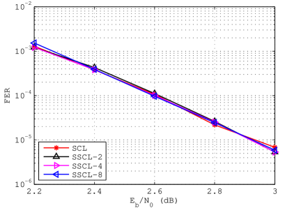
Fig. 2 shows FERs of symbol-based SCL decoding algorithms for a (1024,512) polar code with . Performance differences between these curves are very minor. Therefore, by applying Eq. (6) the symbol-based SCL algorithm does not introduce the obvious performance loss compared with the SCL decoding algorithm. Even with different s, these performance curves are very close. Here, SSCL- denotes the -bit symbol-based SCL decoding algorithm.
IV Two-Stage List Pruning Network
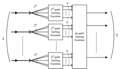
For the -bit symbol-based SCL decoding algorithm, the maximum path expansion coefficient is , i.e. each existing list generates list candidates. Therefore, in the worst-case scenario, most-reliable lists should be sorted out of list candidates. To facilitate this sorting network, we propose a two-stage list pruning network. In the first stage, most-reliable lists are found out among list candidates of each existing list. Therefore, there are list candidates left. In the second stage, the most-reliable lists are sorted out from the list candidates generate by the first stage. The message flow of a two-stage list pruning network is illustrated in Fig. 3.
It is easy to prove that if and , the lists found by the two-stage list pruning network are exactly the most-reliable lists among the list candidates. Therefore, we only consider . In terms of complexity, a smaller leads to a two-stage list pruning network with lower complexity but the probability that the lists found by the two-stage list pruning network are exactly the most-reliable lists among the list candidates decreases as well. This may cause some performance loss.
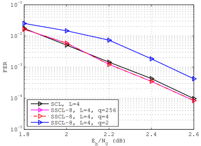
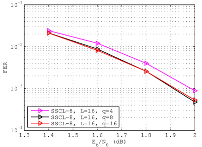
Fig. 4 and 5 show how different s affect FERs of an SSCL-8 decoding algorithm for a (1024, 512) polar code with and , respectively. When and , the SSCL-8 decoding algorithm shows an FER performance loss of about 0.2 dB. When , compared with the FER performance with , there is no observed performance degradation when . The performance loss due to is about 0.08 dB. Therefore, for , to reduce complexity and the latency of the two-stage list pruning network, can be . If the 0.08 dB performance loss is tolerated, can be reduced further to four.
Similarly, as shown in Fig. 6, for a (2048,1433) polar code, the two stage list-pruning network of helps to reduce the complexity of SSCL-8 decoder without the obvious performance loss.
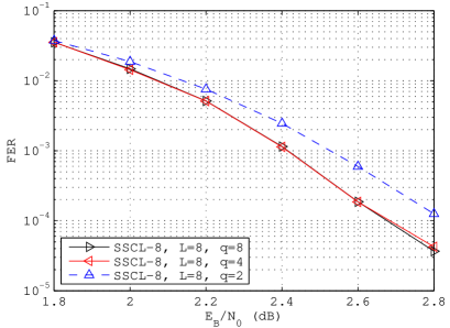
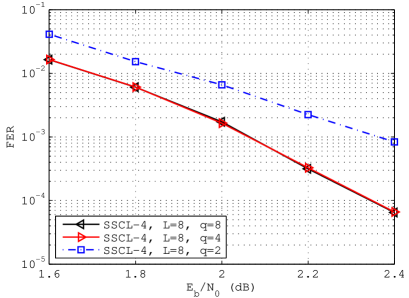
Fig. 7 shows FERs of an SSCL-4 decoder for a (1024,512) polar code with while different s are used. Compared with the case of , there is no obvious FER performance loss when . However, incurs an FER performance loss of about 0.3 dB when the FER is .
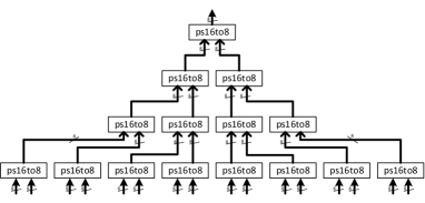
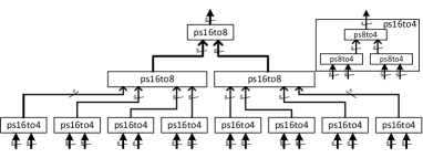
To illustrate advantages of two-stage list pruning network, two tree sorting networks are designed to find the 8 maximal values out of 128 values which can be used in the SSCL-4 decoder with . One is a conventional tree sorting network, shown in Fig. 8, refered to as CTSN. The other is a two-stage tree sorting network with , shown in Fig. 9, refered to as TSTSN. Here, the ”ps16to8” block is a bitonic sorter which finds the maximal 8 values out of 16 values. The bitonic sorter, ”ps8to4”, finds the maximal 4 values out of 8 values.
We implement these two sorting networks and use the RTL compiler to synthesize them with a TSMC 90-nm CMOS technology. The TSTSN has a smaller area and a shorter critical path than the CTSN, as shown in Table I. Besides, the TSTSN does not introduce any obvious performance degradation as shown in Fig. 7.
| Design | area () | Critical Path Delay (ns) |
|---|---|---|
| CTSN | 0.206 | 7.463 |
| TSTSN | 0.134 | 5.861 |
V Conclusion
In this paper, we discuss the generalized symbol-based SC and SCL decoding algorithm for polar codes and derive the recursive procedure to calculate the symbol-based channel transition probability. This recursive procedure needs less additions than the ML scheme used in [17]. A two-stage list pruning network is also proposed to simplify the -list finding network.
References
- [1] E. Arikan, “Channel polarization: A method for constructing capacity-achieving codes for symmetric binary-input memoryless channels,” IEEE Trans. Inf. Theory, vol. 55, no. 7, pp. 3051–3073, July 2009.
- [2] E. Sasoglu, I. Telatar, and E. Arikan, “Polarization for arbitrary discrete memoryless channels,” in ITW, Oct 2009, pp. 144–148.
- [3] C. Leroux, A. Raymond, G. Sarkis, and W. Gross, “A semi-parallel successive-cancellation decoder for polar codes,” IEEE Trans. Signal Process., vol. 61, no. 2, pp. 289–299, Jan 2013.
- [4] K. Niu and K. Chen, “CRC-aided decoding of polar codes,” IEEE Commun. Lett., vol. 16, no. 10, pp. 1668–1671, October 2012.
- [5] A. Eslami and H. Pishro-Nik, “A practical approach to polar codes,” in ISIT, Jul. 2011, pp. 16–20.
- [6] E. Arikan, “Systematic polar coding,” IEEE Commun. Lett., vol. 15, no. 8, pp. 860–862, August 2011.
- [7] I. Tal and A. Vardy, “List decoding of polar codes,” in ISIT, July 2011, pp. 1–5.
- [8] ——, “List decoding of polar codes,” arXiv:1206.0050, Jun. 2012.
- [9] IEEE Standard for Local and Metropolitan Area Networks Part 16: Air Interface for Fixed and Mobile Broadband Wireless Access Systems Amendment 2: Physical and Medium Access Control Layers for Combined Fixed and Mobile Operation in Licensed Bands and Corrigendum 1, IEEE Std. 802.16e-2005, Mar. 2006.
- [10] C. Leroux, I. Tal, A. Vardy, and W. Gross, “Hardware architectures for successive cancellation decoding of polar codes,” in ICASSP, May 2011, pp. 1665–1668.
- [11] A. Alamdar-Yazdi and F. Kschischang, “A simplified successive-cancellation decoder for polar codes,” IEEE Commun. Lett., vol. 15, no. 12, pp. 1378–1380, Dec. 2011.
- [12] C. Zhang and K. Parhi, “Latency analysis and architecture design of simplified sc polar decoders,” IEEE Trans. Circuits Syst. II, vol. 61, no. 2, pp. 115–119, Feb. 2014.
- [13] G. Sarkis and W. Gross, “Increasing the throughput of polar decoders,” IEEE Commun. Lett., vol. 17, no. 4, pp. 725–728, Apr. 2013.
- [14] G. Sarkis, P. Giard, A. Vardy, C. Thibeault, and W. Gross, “Fast polar decoders: Algorithm and implementation,” IEEE Journal on Selected Areas in Communications, vol. 32, no. 5, pp. 946–957, May 2014.
- [15] C. Zhang and K. Parhi, “Low-latency sequential and overlapped architectures for successive cancellation polar decoder,” IEEE Trans. Signal Process., vol. 61, no. 10, pp. 2429–2441, May 2013.
- [16] J. Lin and Z. Yan, “Efficient list decoder architecture for polar codes,” in ISCAS, 2014, to appear.
- [17] B. Li, H. Shen, and D. Tse, “Parallel decoders of polar codes,” arXiv:1309.1026, September 2013.