Spin-orbit coupled Bose-Einstein condensates in a one-dimensional optical lattice
Abstract
The realization of artificial gauge fields and spin-orbit coupling for ultra-cold quantum gases promises new insight into paradigm solid state systems. Here we experimentally probe the dispersion relation of a spin-orbit coupled Bose-Einstein condensate loaded into a translating optical lattice by observing its dynamical stability, and develop an effective band structure that provides a theoretical understanding of the locations of the band edges. This system presents exciting new opportunities for engineering condensed-matter analogs using the flexible toolbox of ultra-cold quantum gases.
pacs:
03.75.Kk, 03.75.Mn, 03.75.LmSpin-orbit coupling — the interaction between a particle’s spin and its mechanical motion — plays a prominent role in condensed matter physics Nagaosa et al. (2010). Even though the spin-orbit interaction is usually relatively weak, it can be important for bands close to the Fermi level Haverkort et al. (2008). The combination of spin-orbit coupling with a periodic potential resulted in the prediction and discovery of topological insulators Kane and Mele (2005); Fu et al. (2007). Such spin-orbit coupled lattice systems, with the addition of strongly correlated many-body effects, can exhibit novel phases Chen et al. (2010). These systems have transformed our understanding and classification of insulators and have become a significant focus of recent research Hasan and Kane (2010); Qi and Zhang (2011). They afford the possibility of studying new phase transitions and realizing exotic spin models Jackeli and Khaliullin (2009).
Simulating model Hamiltonians relevant to condensed matter physics has developed into a major area of research for experiments with dilute gas Bose-Einstein condensates and degenerate Fermi gases Lewenstein et al. (2007); Bloch et al. (2012). Quantum gases in optical lattices are nearly disorder free and often exhibit long coherence times Lewenstein et al. (2007); Bloch et al. (2012). Additionally, quantum gases allow the modification of the interparticle interactions, e.g. by tuning the two-body scattering length Donley et al. (2001) or engineering long range dipolar interactions Müller et al. (2011), creating great flexibility for implementing model Hamiltonians. While many electronic condensed-matter systems naturally exhibit a band structure due the periodicity of an underlying crystal lattice, in ultra-cold quantum gases band structures can be engineered by loading the system into an optical lattice. Both an optical lattice potential Fallani et al. (2004) and spin-orbit coupling Higbie and Stamper-Kurn (2002) can strongly modify the single-particle dispersion relation of a quantum gas, resulting in novel band structures.
In this letter we perform a detailed study of a Bose-Einstein condensate (BEC) with spin-orbit coupling Higbie and Stamper-Kurn (2002); Lin et al. (2011); Fu et al. (2011); Zhang et al. (2012); Qu et al. (2013) loaded into a shallow, translating one-dimensional optical lattice. We find that the system exhibits a number of dynamical instabilities induced by the periodic dispersion relation of the lattice Zhang and Zhang (2013). The instabilities are marked by an initial exponential growth of excitations in the BEC, and are most significant in the vicinity of a band gap. We characterize the strengths of the instabilities by the loss rate of condensate atoms and find that a dynamical instability is present for lattice velocities exceeding a critical velocity within the first Brillouin zone Wu and Niu (2001); Fallani et al. (2004). The strength of the instability depends on both the lattice speed and direction of motion. This is an indicator of the lack of Galilean invariance in the presence of the spin-orbit coupling Zhu et al. (2012). We compare our results with a Bogoliubov analysis of the system, finding good agreement.
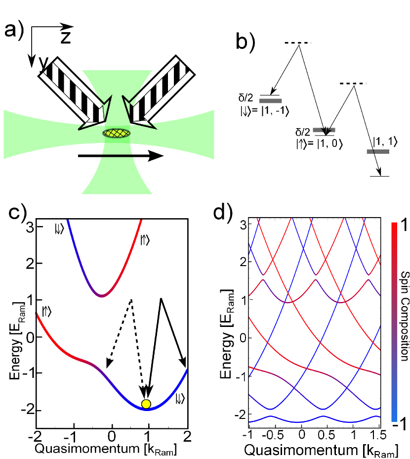
We begin by providing a brief description of our experimental setup — full details can be found in the Supplementary Material Sup . Spin-orbit coupling in BECs can be induced by Raman dressing schemes Lin et al. (2011); Dalibard et al. (2011); Galitski and Spielman (2013), and the geometry of our experiment is shown schematically in Fig. 1(a). The Raman lasers couple the and states of a 87Rb BEC in the F=1 hyperfine manifold. A 10 G bias magnetic field causes a sufficiently large quadratic Zeeman splitting such that the state is far from resonance and can be eliminated, hence realizing an effective spin- system. The system without the one-dimensional lattice is modeled by the single-particle Hamiltonian Lin et al. (2011). Here is the atomic mass, is the quasimomentum in the spin-orbit direction and are the Pauli matrices. The spin-orbit coupling strength is , where is the wavevector of the Raman beams in the -direction, is the detuning, and is the Rabi frequency. A typical band structure for our parameters is shown in Fig. 1(c), where the band energies are .
Two additional laser beams with nm and small frequency difference generate the translating optical lattice. The lattice beams are collinear with the Raman lasers such that . The single-particle Hamiltonian of the spin-orbit coupled lattice system is . The lattice velocity can be adjusted by varying the frequency difference between the two lattice beams. For the experiments presented in this manuscript, , where . The presence of the optical lattice extends the spin-orbit coupled bands in Fig. 1(c) to the Bloch spectrum in Fig. 1(d). In the repeated zone scheme the Bloch spectrum is constructed through copies of the spin-orbit bands shifted by integers of the reciprocal lattice vector in quasimomentum and in energy, where . Gaps open in the Bloch spectrum wherever intersections between and occur. The width of the gap depends on the lattice depth and the overlap between the spin composition of the states coupled by the lattice beams. Typically the gap width corresponding to is larger than that corresponding to . This is evident in Fig. 1(d), where the energy gaps are largest for in both the lower as well as the upper dressed bands. Physically, the band gaps can be understood from multi-photon resonances in which the momentum of the atoms can be changed coherently by multiples of the reciprocal lattice vector .
Before describing the experimental results, it is instructive to introduce an effective band structure picture. As the translating optical lattice potential is time dependent in the lab frame, it is convenient to go into the frame in which the optical lattice is stationary. This results in the Hamiltonian . With a simple Galilean substitution, , one obtains (where we have left out a constant energy term .) In addition to the lattice potential, is non-trivially different from as the term , which can be interpreted as an effective detuning of the Raman beams, is dependent on the frame velocity . This is due to the broken Galilean invariance of the spin-orbit coupled BEC. Physically this arises because the Raman lasers generating the spin-orbit coupling provide a fixed frame of reference.
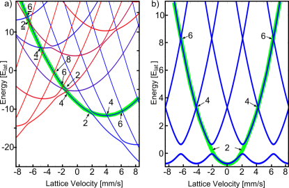
To understand the band structure, we trace the location of the BEC in the single-particle band spectra as a function of the lattice velocity. The BEC is initially assumed to be in the ground state of the spin-orbit coupled band with a finite quasimomentum, , which is approximately conserved when the optical lattice is introduced Cladé et al. (2009). The energies , taken from the Bloch spectrum of at , are shown as a function of lattice velocity in Fig. 2(a) for , , and , where . We label the avoided crossings within these effective band structures by integers that indicate the photon processes involved, . Resonances occurring between the lower and upper spin-orbit bands [] are denoted by an underlined number . When the spin-orbit coupled BEC is adiabatically loaded into the translating lattice, it occupies a state near the free particle dispersion (thick green line). It is interesting to note that the ordering of the band edges is not straightforward, and the positions of the band edges are not equally spaced. The exact ordering and position strongly depend on the chosen parameters , , and the ratio . For comparison, Fig. 2(b) presents the analogous band structure for a BEC in a translating lattice but without spin-orbit coupling. As is well-known in this case, the effective band structure and the BEC location (thick green line) are symmetric about the direction of motion, the band edges are equally spaced, and the effective dispersion relation recovers the Bloch spectrum.
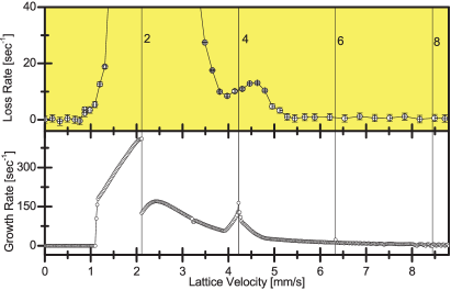
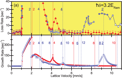
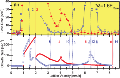
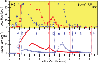
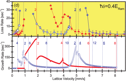
To experimentally probe the dynamical instability we measure the loss spectra for the system as a function of the velocity of the optical lattice. Our experiments begin with a nearly pure 87Rb BEC in the ground state in the presence of spin-orbit coupling with before ramping up a translating optical lattice with Sup . We hold the BEC in the lattice potential for 100 ms, during which excitations caused by instabilities can grow and population is lost from the BEC. The experimental results for the loss rate as a function of the lattice velocity, for four different values of the Raman detuning , are plotted in the upper panels of Fig. 3(a–d). In the absence of Galilean invariance, we must differentiate between the two translating directions for the optical lattice. In Fig. 3 we plot negative (positive) velocities in dashed open blue circles (solid red triangles), corresponding to the dashed (solid) arrows in Fig. 1(c). With this convention a lattice translating in the positive direction couples to states that resemble free particles, while a lattice translating in the negative direction couples to states that are strongly modified by the spin-orbit coupling. For comparison, we have also performed these measurements without spin-orbit coupling (see Fig. 4) and for this case find agreement with prior experimental work Fallani et al. (2004).
We model our experiment using the Bogoliubov-de Gennes (BdG) equations based on a one-dimensional mean-field description of a homogeneous BEC Sup . We identify the quasi-particle mode with the largest imaginary part of the energy, corresponding to the largest initial growth rate, and plot this rate as a function of velocity in the lower panels of Fig. 3(a–d). The theoretical results provide a good understanding of the experimental measurements. While the theoretically calculated growth rates are not identical to the experimental loss rates presented in the upper panels of Fig. 3, they have previously been found to be a reasonable indication of the strength of dynamical instability Fallani et al. (2004). Both the experimental data and the numerical results demonstrate that the critical speed for the onset of the dynamical instability is different for the two directions of motions. This is particularly evident in the experimental and numerical results for the smaller detunings of and in Fig. 3(c,d) near mm/s, where the critical velocity is smaller for the negative direction. Above the critical velocity the dynamical instability is most significant in the vicinity of the band edges. Loss occurs in all higher bands as well, but the loss rate in higher bands is significantly reduced.
The dynamical stability of the BEC is quite different for the two directions of motion. In Fig. 3(a–d) the behavior of the loss and growth rates for the positive direction of motion (red solid triangles) is very similar to that of the case without spin-orbit coupling shown in Fig. 4. However, in the negative direction of motion (blue open circles) the behavior is strongly modified. For example in Fig. 3(a) for , a pronounced additional loss feature appears centered around mm/s, shifting to smaller velocities for smaller in Fig. 3(b–d). This feature is caused by the two photon resonance between and (i.e. the lattice resonance between the lower and upper spin-orbit bands). For comparison, the large loss feature near mm/s is due to the photon resonance within the lowest spin-orbit band. Even though both of these loss features arise from two photon couplings, the feature is weaker. This is in part due to the reduced overlap of the spin composition between and . For the positive direction of motion of the lattice in Fig. 3(a–d) the resonance between and occurring at large velocity is suppressed by the small overlap in spin composition for our chosen parameters. For example, with , such a resonance occurs at mm/s but the modification to the Bloch spectrum is negligible. Another loss feature near mm/s in Fig. 3(a) in the positive direction corresponds to the photon resonance, and is shifted to smaller velocities in the negative direction. In the experimental results for the negative direction it cannot be differentiated from the dominant band edge, and is diminished due to the smaller overlap of the spin compositions.
In conclusion, we have studied the rich dispersion relation of a spin-orbit coupled BEC in a weak optical lattice by probing the losses of the system as a function of lattice velocity. Our study opens the door to investigations on the effect of spin-orbit coupling for the superfluid-to-Mott insulator transition Cole et al. (2012) and the physics of strong spin-orbit correlated Mott insulators Radić et al. (2012). Our methods have a potential application for the realization of the fractional quantum Hall affect without Landau levels using a spin-orbit coupled lattice Cooper and Dalibard (2011).
Acknowledgements: PE, MAK, and CH acknowledge funding from NSF and ARO. YZ and MJD acknowledge financial support
from the Australian Research Council Discovery Project DP1094025.
I Supplementary Materials:
II Theoretical stability analysis
To model the experimental results, we perform a stability analysis in the mean-field treatment for the homogeneous BEC. We start from the one-dimensional Gross-Pitaevskii equation (GPE) in dimensionless form
| (1) |
where with . The units of energy, time and length are , and respectively. The dimensionless quantities are defined as and . The parameter is the nonlinear coefficient that is proportional to the s-wave scattering length. For this analysis we approximate the system by setting all of the s-wave scattering lengths equal. This is a reasonable assumption for the chosen experimental states where the differences in intra- and inter-component scattering lengths are small.
We calculate the Bloch spectrum and corresponding Bloch states of the GPE using the normalization condition within a unit cell. We choose a weak nonlinearity such that our nonlinear Bloch states converge for all lattice velocities. We have verified that our results are qualitatively independent of the exact value of . The dynamical stability of the Bloch states is analyzed using linear perturbation theory and making the ansatz
| (2) |
The Bloch state of interest is where , is the chemical potential and is the quasimomentum of the Bloch state into which the BEC is loaded in the experiment. and are perturbation amplitudes, and and are the quasimomentum and frequency of the perturbation respectively. Substituting Eq. (2) into Eq. (1) results in the Bogoliubov de Gennes (BdG) equations
| (3) |
with the BdG Hamiltonian
| (4) |
Here
| (5) | ||||
| (6) |
with
| (7) |
The system of equations (3) is then solved for the eigenvalues . If any is complex-valued, the Bloch state is dynamically unstable. The growth rate of excitations in the system is estimated as the largest imaginary value of any , as this will dominate the growth.
To clearly convey the underlying physics, a single-particle description is used in the analysis in the main text. However, for the stability analysis shown in Fig. 3 and Fig. 4 of the main text, the nonlinearity of the system is taken into account. The use of the single particle description is justified as the nonlinearities due to repulsive interactions primarily contribute an overall shift to the Bloch spectrum Krämer et al. (2003).
III Experimental methods
Our experiment begins with a BEC of 87Rb containing approximately atoms in the hyperfine state. The BEC is held in an optical dipole potential with harmonic trapping frequencies Hz, where is the vertical direction. Two crossed Raman lasers with a wavelength in the range of nm are shone onto the BEC and propagate along the direction respectively with a relative angle . The Raman lasers couple the and states in the F=1 hyperfine manifold. A 10 G magnetic bias field causes a quadratic Zeeman splitting of , where , so that the state is far from resonance and can be eliminated. This realizes an effective spin- system. Two additional laser beams with nm and small frequency difference generate the translating optical lattice. The lattice beams are collinear with the Raman lasers such that . The ratio of the recoil momenta is , and the recoil energies are kHz and Hz. The spin-orbit coupled BEC is adiabatically loaded into the optical lattice by linear ramps of the lattice depth over 10 ms from to . The adiabaticity is verified by turning on and off the lattice in two subsequent 2 ms long linear ramps of the intensity and checking for the absence of heating and additional momentum components. Only velocities where no population transfer to additional momentum states and no heating of the BEC is observed are utilized in these experiments. This check is conducted for BECs both with and without spin-orbit coupling. Following each experimental realization, the Raman and lattice beams are jumped off projecting the BEC onto the bare hyperfine and momentum states followed by Stern-Gerlach separation during 11.5 ms time-of-flight period and absorption imaging.
III.1 Further experimental considerations
The analysis presented in the manuscript assumes that the minimum of the lower spin-orbit coupled band, , at is occupied by the BEC. For the experimental realization, a nearly pure BEC (with minimal thermal component) is indeed loaded into the minimum of the spin-orbit band structure at . However, for some negative velocities taken at the smallest Raman detuning there is a small fraction of the atoms occupying a quasimomentum near , following the 100 ms in the translating optical lattice. For all other experimental data presented in the main text, the BEC remains near for the duration of the experiment. In all experimental images taken after the wait time in the translating optical lattice, a discernible thermal cloud is observed. These experimental considerations are not accounted for in the BdG analysis.
For numerous detunings and lattice velocities we have verified that the losses during the wait time in the translating optical lattice fit well to an exponential decay. The loss rates presented in Fig. 3 and Fig. 4 of the main text are determined by measuring the atom number after the 100 ms wait time for both the stationary lattice and for the translating lattice. Assuming exponential decay, we calculate the contribution to the loss rate from the moving lattice. These are the quantities plotted in Fig. 3 and Fig. 4. The vertical error bars reflect the uncertainty in the measurement of the atom numbers. Long term drifts in these measurements are suppressed by alternating the direction of subsequent optical lattice velocities during experimental realizations. The horizontal error bars reflect the uncertainty of the quasimomentum due to mismatch of the group velocities for the system with and without the lattice Fallani et al. (2004). For the data presented in Fig. 3 we only probe velocities where the momentum imparted by the translating lattice is small.
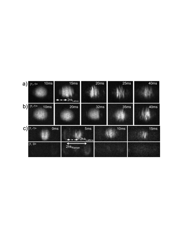
The discussion in the manuscript focuses on the role of the dynamical instability. However, we note that an energetic instability is also present in this system as well, but that it does not play a significant role for the observed dynamics. The energetic instability is suppressed in our experiments by the small initial thermal fraction and the slower timescales associated with atom losses caused by the energetic instability Fallani et al. (2004). The dominant nature of the dynamical instability is made evident by the observation of density modulations in the BEC Fallani et al. (2004) as shown in Fig. 5. In Fig. 5(a) we present an example for the case of a BEC in a translating optical lattice with mm/s, but without spin-orbit coupling. We find that similar density modulations appear in the spin-orbit coupled lattice system for both translational directions of the lattice, e.g. in Fig. 5(b) with mm/s, , and Fig. 5(c) with mm/s, . The onset of the density modulations in Fig. 5(c), which is taken for a velocity near the band edge, is accompanied with a momentum transfer of for a small but noticeable fraction of the atoms. The transferred population, occupying , acquires nearly balanced spin composition.
III.2 Single particle band structure
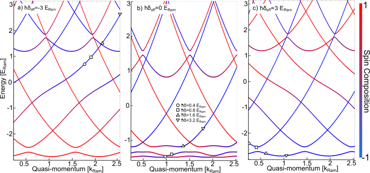
While the effective dispersion relation presented in Fig. 2a allows the easy determination of the band edges, it can be seen from that a single band structure can be chosen by fixing . To realize such a case, the lattice velocity and Raman detuning can always be adjusted together such that constant. When varying under this constraint, the BEC effectively changes quasimomentum within a fixed dispersion relation. This is demonstrated in Fig. 6 for fixed to and . For fixed , the quasimomentum of the BEC is given by , where is dependent on . This is showcased in the supplementary movie file for ranging from to with the locations of the data taken in Fig. 3 overlaid. Only values of positive can be probed within these fixed dispersion relations for the trapped BEC, which is prepared to the global minimum of the spin-orbit band structure. When changes sign, the quasimomentum of the BEC changes sign as well.
References
- Nagaosa et al. (2010) N. Nagaosa, J. Sinova, S. Onoda, A. H. MacDonald, and N. P. Ong, Rev. Mod. Phys. 82, 1539 (2010).
- Haverkort et al. (2008) M. Haverkort, I. S. Elfimov, L. Tjeng, G. Sawatzky, and A. Damascelli, Phys. Rev. Lett. 101, 026406 (2008).
- Kane and Mele (2005) C. L. Kane and E. J. Mele, Phys. Rev. Lett. 95, 226801 (2005).
- Fu et al. (2007) L. Fu, C. L. Kane, and E. J. Mele, Phys. Rev. Lett. 98, 106803 (2007).
- Chen et al. (2010) G. Chen, R. Pereira, and L. Balents, Phys. Rev. B 82, 174440 (2010).
- Hasan and Kane (2010) M. Z. Hasan and C. L. Kane, Rev. Mod. Phys. 82, 3045 (2010).
- Qi and Zhang (2011) X.-L. Qi and S.-C. Zhang, Rev. Mod. Phys. 83, 1057 (2011).
- Jackeli and Khaliullin (2009) G. Jackeli and G. Khaliullin, Phys. Rev. Lett. 102, 017205 (2009).
- Lewenstein et al. (2007) M. Lewenstein, A. Sanpera, V. Ahufinger, B. Damski, A. Sen(De), and U. Sen, Advances in Physics 56, 243 (2007).
- Bloch et al. (2012) I. Bloch, J. Dalibard, and S. Nascimbène, Nat. Phys. 8, 267 (2012).
- Donley et al. (2001) E. A. Donley, N. R. Claussen, S. L. Cornish, J. L. Roberts, E. A. Cornell, and C. E. Wieman, Nature 412, 295 (2001).
- Müller et al. (2011) S. Müller, J. Billy, E. A. L. Henn, H. Kadau, A. Griesmaier, M. Jona-Lasinio, L. Santos, and T. Pfau, Phys. Rev. A 84, 053601 (2011).
- Fallani et al. (2004) L. Fallani, L. De Sarlo, J. E. Lye, M. Modugno, R. Saers, C. Fort, and M. Inguscio, Phys. Rev. Lett. 93, 140406 (2004).
- Higbie and Stamper-Kurn (2002) J. Higbie and D. M. Stamper-Kurn, Phys. Rev. Lett. 88, 090401 (2002).
- Lin et al. (2011) Y.-J. Lin, K. Jimenez-Garcia, and I. B. Spielman, Nature 471, 83 (2011).
- Fu et al. (2011) Z. Fu, P. Wang, S. Chai, L. Huang, and J. Zhang, Phys. Rev. A 84, 043609 (2011).
- Zhang et al. (2012) J.-Y. Zhang, S.-C. Ji, Z. Chen, L. Zhang, Z.-D. Du, B. Yan, G.-S. Pan, B. Zhao, Y.-J. Deng, H. Zhai, S. Chen, and J.-W. Pan, Phys. Rev. Lett. 109, 115301 (2012).
- Qu et al. (2013) C. Qu, C. Hamner, M. Gong, C. Zhang, and P. Engels, Phys. Rev. A 88, 021604 (2013).
- Zhang and Zhang (2013) Y. Zhang and C. Zhang, Phys. Rev. A 87, 023611 (2013).
- Wu and Niu (2001) B. Wu and Q. Niu, Phys. Rev. A 64, 061603 (2001).
- Zhu et al. (2012) Q. Zhu, C. Zhang, and B. Wu, Europhys. Lett. 100, 50003 (2012).
- (22) See Supplemental Material at [URL will be inserted by publisher] for a detailed description of the theoretical stability analysis, further details of the experimental methods and considerations, and visualisation of the band structure in terms of the effective detuning.
- Dalibard et al. (2011) J. Dalibard, F. Gerbier, G. Juzeliūnas, and P. Öhberg, Rev. Mod. Phys. 83, 1523 (2011).
- Galitski and Spielman (2013) V. Galitski and I. B. Spielman, Nature 494, 49 (2013).
- Cladé et al. (2009) P. Cladé, S. Guellati-Khélifa, F. Nez, and F. Biraben, Phys. Rev. Lett. 102, 240402 (2009).
- Cole et al. (2012) W. S. Cole, S. Zhang, A. Paramekanti, and N. Trivedi, Phys. Rev. Lett. 109, 085302 (2012).
- Radić et al. (2012) J. Radić, A. Di Ciolo, K. Sun, and V. Galitski, Phys. Rev. Lett. 109, 085303 (2012).
- Cooper and Dalibard (2011) N. R. Cooper and J. Dalibard, Europhys. Lett. 95, 66004 (2011).
- Krämer et al. (2003) M. Krämer, C. Menotti, L. Pitaevskii, and S. Stringari, Eur. Phys. J. D 27, 247 (2003).