Suppression of single-molecule-conductance fluctuations using extended anchor groups on graphene and carbon-nanotube electrodes
Abstract
Devices formed from single molecules attached to noble-metal electrodes exhibit large conductance fluctuations, which inhibit their development as reproducible functional units. We demonstrate that single molecules with planar anchor groups attached carbon-based electrodes are more resilient to atomic-scale variation in the contacts and exhibit significantly-lower conductance fluctuations. We examine the conductance of a 2,6-dibenzylamino core-substituted naphthalenediimide (NDI) chromophore attached to carbon electrodes by either phenanthrene anchors or by more extended anchor groups, which include OPE spacers. We demonstrate for the more spatially-extended anchor groups, conductance fluctuations are significantly reduced. The current-voltage characteristic arising from long-range tunnelling, is found to be strongly non-linear with pronounced conductance suppression below a threshold voltage of approximately 2.5 volts.
pacs:
31.15.ae, 31.15.at, 31.15.es, 71.15.Mb, 73.23.Ad, 73.63.Fg, 73.63.RtCombined experimental and theoretical studies have provided new insights into the interplay of molecular conformation, electronic structure and electrical conductance. g1 in single-molecule electronic devices. It is clear that measured conductance values depend on the atomic-scale contact geometry of the electrodes, g2 temperature, g3 the local environment of the system (vacuum or air, solvent, etc.) g4 and molecular features such as the extent of conjugation, salomon_comparison_2003 ; kushmerick_effect_2002 the nature of the terminal anchor groups (e.g. thiol, amine, carboxylic acid), li_conductance_2006 the detailed conformation g8 and tilt angle g9 of the molecule in the junction, and on quantum coherence and interference of electrons transiting the molecule sedghi_long-range_2011 ; g11 .
With a view to developing stable sub-10nm electronic devices, a great deal of effort has been devoted to understanding the interplay between terminal anchor groups and metallic electrodes. The ideal molecular anchor group should form reproducible and mechanically-stable contacts with well-defined binding sites and strong electronic coupling to the nanoelectrodes. g12 Recently, chemical synthesis was used to vary the anchor groups within a family of molecules and the relative anchoring performance of four different terminal groups (SH, pyridyl (PY), NH2 and CN) was measured and calculated. This study revealed the following sequence for junction formation probability and stability: PY SH NH2 CN. hong_single_2011 In common with other studies of single molecules attached to gold electrodes, broad variations in the measured conductances are observed, which suggests that alternative electrodes to gold are needed, if reliable and reproducible devices are to be developed. salomon_comparison_2003 Alternatives based on surface grafting via covalent bonds, such as carbon-carbon, ranganathan_covalently_2001 metal-carbon cheng_situ_2011 and silicon-carbon g16 also exhibit significant sample-to-sample fluctuations.
In this paper, as a possible route to reducing fluctuations, we examine the use of extended planar anchor groups attached via interactions to either graphene or carbon nanotube (CNT) electrodes. Recent experiments suggest that carbon-based electrodes are a viable alternative to the more commonly-used noble metals g17 ; prins_room-temperature_2011 . For example, Prins et al prins_room-temperature_2011 created a few-nm-wide gap in graphene, via feedback controlled electroburning and carried out room temperature, gate controlled measurements on a single molecule bridging the gap. Similarly Marquardt et al marquardt_electroluminescence_2010 used electrical breakdown to form nanogaps in free-standing CNTs and bridged the gap with a single molecule.
Nanogap electrodes of this kind have several advantages over more-commonly used noble-metal electrodes, because the absence of screening makes it easier to gate the molecule and their planar structure makes it possible to image the molecule in situ. In this paper, we perform simulations based on density-functional theory (DFT) to demonstrate that such carbon-based electrodes have the further advantage of allowing the suppression of conductance fluctuations arising from atomic-scale disorder by increasing the size of planar anchor groups.
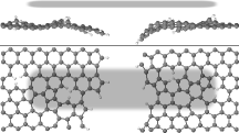
As a specific example, we investigate the electronic properties of a rod-like molecule, closely related to that measured by Marquardt et al marquardt_electroluminescence_2010 ; blaszczyk_synthesis_2006 , which has a 2,6-dibenzylamino core-substituted naphthalenediimide (NDI) functional group, connected via oligophenylene ethynylene (OPE) linkers to phenanthrene terminal groups, as shown in Fig. 1. This contains the same NDI core as that measured by Marquardt et al, but theirs contains three OPEs in the left and right linkers, whereas the molecule in Fig. 1 contains only a single OPE in each linker. The longer 3-3 OPE molecule of Ref. marquardt_electroluminescence_2010, , when attached to electrodes, is prohibitively expensive to simulate, whereas the 1-1 OPE of Fig. 1 is more tractable.
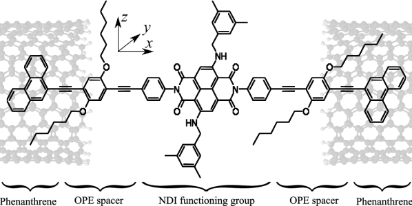
To model carbon-based electrodes, we couple the planar end groups of the molecule of fig. 1 to a large-diameter single-walled, metallic armchair CNT-electrodes, via overlap, as shown in Fig. 1. Since the CNTs are locally flat on the scale of the phenanthrene terminal groups and OPE bridge, our results also capture generic transport properties obtained using alternative carbon-based electrodes, such as multi-wall CNTs and mono- or few-layer graphene.
Our first goal is to compute the characteristics of this molecule, and show that the threshold voltage measured by Marquardt et al is an intrinsic property of this class of molecules. Our second goal is to show that by increasing the size of the planar anchor groups, the sensitivity to lattice defects can be reduced.
I Theoretical method
The structure shown in Fig. 1 involves over 1100 atoms and therefore an efficient computational scheme is needed to determine its electrical properties. The first step is to calculate the relaxed geometry, for which we use the DFT code SIESTA. soler_siesta_2002 A double-zeta polarized basis set is chosen, the exchange correlation is described by GGA perdew_generalized_1996 and the atoms are relaxed until all forces are less than 0.05 eV/Å. The size of our molecules prevents the inclusion of van der Waals interaction within a currently-tractable calculation. Nevertheless it is known that van der Waals interactions tend to increase the binding energy of smaller molecules to electrodes, and the effect on transmission is to make the anchor groups more transparent. In our case however, the transmission is dominated by tunnelling through the HOMO-LUMO gap and therefore increasing the transparency of the contacts is not likely to produce a significant change. The relaxation consists of several steps: the CNT leads and the molecule are relaxed separately, and then the whole system again relaxed. After introducing lattice defects into the once-relaxed system, the structure is again relaxed. For consistency, the same force tolerance is used in all cases.
For the purpose of structure relaxation, the system is infinitely-periodic along -axis and for the small (large) end groups, comprises nanotube sequences between the molecules made up of 17 (21) CNT unit cells. These are long enough to ensure convergence of the mean-field DFT Hamiltonian parameters, which are later employed to compute transmission coefficients. On the surfaces of the nanogaps, the armchair CNTs are terminated with hydrogen atoms to saturate the dangling bonds.
After relaxing the whole periodic system, the underlying DFT tight-binding Hamiltonian is extracted, within a double-zeta basis-set representation and the transmission coefficient is calculated using an equilibrium implementation of the ab-initio transport code SMEAGOL, rocha_spin_2006 which is based on a Greens-function scattering technique. At temperature , and bias , the current can be calculated using the integral:
where is the Fermi function.
II Lattice defect resilience
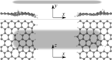
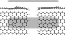
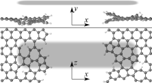
To show that extended anchor groups make the system resilient to lattice defects, we introduce defects in the lattice of the CNT electrodes mainly around the anchor groups, and allow the bulk of the CNT to remain pristine. We introduce defects in two stages: first, we remove 6-6 carbon atoms from the edges, and introduce 1-1 Stone–Wales defects g24 and 1-1 vacancies in contact region of each electrode, which consists of the last couple of unit cells in the vicinity of the end of the CNTs.
SubFig1)subfig:jsf
SubFig1)subfig:jlf
SubFig2)subfig:jsm
SubFig2)subfig:jlm
SubFig1)subfig:ets
SubFig1)subfig:bcs
SubFig2)subfig:etl
SubFig2)subfig:bcl
In the second stage, we double the concentration of each kind of defect. In the presence of such defects, the relaxed geometries of the CNT surfaces in the vicinity of the anchor groupss are shown in Fig. 2, where for clarity, both side and top views are shown and the attached molecule is represented simply by grey shaded regions.
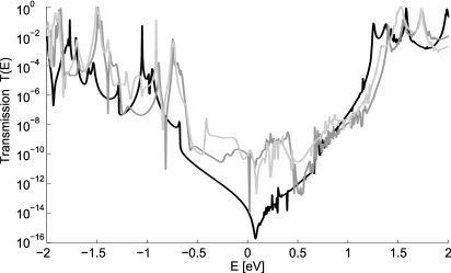
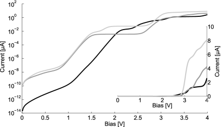
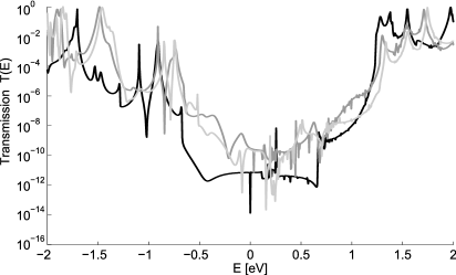
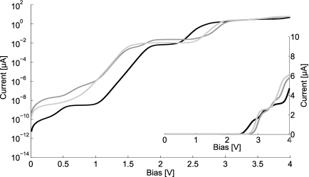
To demonstrate that fluctuations are reduced in the presence of more extended anchor groups, we consider the case of ’small’ and ’large’ anchor groups. The small-anchor configuration is shown in Fig. 1, where only the phenanthrene group is in direct contact with the CNT. For the large anchor group, we consider the case where the OPE spacers also overlay the CNT. For the small and large anchors, attached to CNTs containing no defects and two non-zero concentrations of defects, transmission and curves are shown in Fig. 3. Interestingly, above 3V, we find that lattice defects increase the electrical conductance, by broadening the Breit-Wigner resonances around V. This is particularly striking for the small anchor groups.
To quantify the conductance fluctuations of the results presented in Fig. LABEL:subfig:bcs and LABEL:subfig:bcl, at each voltage , we compute the finite-voltage conductance , for each of the three curves in Fig. LABEL:subfig:bcs and LABEL:subfig:bcl. At each voltage, we then compute the mean and standard deviation of each set of three curves. For the small and large anchor groups, we denote the standard deviation and respectively. As a measure of their relative conductance fluctuations over a given voltage window, we define the ratio
| (1) |
When integrating from 0 V up to 4 V, we find , but when integrating only above the switch-on voltage from 3V to 4V, we find . Both cases clearly demonstrate that the curves with large anchor groups are far more resilient to lattice defects than those with smaller anchor groups.
In common with the measured 3-3 OPE molecule marquardt_electroluminescence_2010 , we find that curves of our 1-1 OPE are strongly non-linear, with a threshold voltage for charge transport of , which supports that this threshold voltage is an intrinsic feature of this class of molecules. The 3-3 OPE threshold voltage was measured to be ca. , whereas in our case the 1-1 OPE threshold is predicted to be . In our calculations, transport takes place by phase-coherent tunnelling and since the Fermi energy is close to the centre of the HOMO-LUMO gap, is approximately twice the value of the HOMO-LUMO gap, which is larger for the smaller molecule.
III Conclusions
Single-molecule electronics is an embryonic technology, whose development is hampered by conductance fluctuations due to atomic-scale variation at the contacts to electrodes. Using ab-initio methods, we have demonstrated that conductance fluctuations of a single molecule bridging carbon-based electrodes can be significantly decreased by increasing the size of planar aromatic anchor groups, which bond to the electrodes. As a specific example, we have examined the 2,6-dibenzylamino core-substituted naphthalenediimide (NDI) chromophore attached to carbon nanotube electrodes, which is closely related to a molecule measured recently by Marquardt et al. marquardt_electroluminescence_2010 In agreement with their measurements, we find a non-linear with strong current suppression at low voltages. The agreement between their threshold and our numerical value is of course a coincidence, because the molecule measured by Marquardt et al marquardt_electroluminescence_2010 is similar, but not identical to ours. Furthermore it is well known that DFT may not predict accurately the position of the Fermi energy relative to the HOMO and LUMO levels and we have neglected the possibility that the molecule can become charged. Nevertheless our calculations demonstrate that when the Fermi energy is located far from the HOMO or LUMO resonance peaks, a threshold voltage with a value close to the one measured by Marquardt et al marquardt_electroluminescence_2010 arises naturally within a phase-coherent tunnelling picture of transport, of the kind discussed in Ref. sedghi_long-range_2011, .
The transition from noble-metal-based electrodes to carbon-based electrodes represents a paradigm shift for molecular electronics. For the future, it will be fruitful to examine a range of alternative planar anchor groups, including pyrene and pyrene derivatives, which are known to bind strongly to graphene and CNTs, g25 larger polycyclic aromatics and molecules terminated by multiple anchor groups.
Acknowledgement
We gratefully acknowledge discussions with Iain Grace and funding from the Marie-Curie ITNs FUNMOLS and NANOCTM. Funding is also provided by EPSRC and METRC.
Supporting information
The relaxed coordinates of the CNT-molecule-CNT systems with lattice defects, together with the corresponding 3D rotatable images are available at peterfalvi.web.elte.hu/Bulky.html.
References
- (1) J. M. Tour, Acc. Chem. Res. 33, 791–804, (2000); R. L. Carroll and C. B. Gorman, Ang. Chem. Int. Ed. 41, 4378–4400, (2002); G. Maruccio, R. Cingolani and R. Rinaldi, J. Mater. Chem. 14 542–554, (2004); A. Troisi and M. A. Ratner, Small 2, 172–181, (2006); D. K. James and J. M. Tour, Aldrichim. Acta 39, 47-56, (2006); N. Weibel, S. Grunder and M. Mayor, Org. Biomol. Chem. 5, 2343–2353, (2007); F. Chen, J. Hihath et al., Ann. Rev. Phys. Chem. 58, 535–564, (2007); H. B. Akkerman and B. Boer, J. Phys: Cond. Mat. 20, 013001, (2008).
- (2) R. L. McCreery, U. Viswanathan et al., Faraday Discuss. 131, 33–43, (2006); S. M. Lindsay and M. A. Ratner, Adv. Mat. 19, 23–31, (2007); Y. Hu, Y. Zhu, H. Gao and H. Guo, Phys. Rev. Lett. 95, 156803, (2005); C. Li, I. Pobelov et al., J. Am. Chem. Soc. 130, 318–326, (2007).
- (3) W. Haiss, H. v. Zalinge et al., Faraday Discuss. 131, 253–264, (2006); D. R. Jones and A. Troisi, J. Phys. Chem. C 111, 14567–14573, (2007).
- (4) D. P. Long, J. L. Lazorcik et al., Nature Mat. 5, 901–908, (2006); H. Cao, J. Jiang et al., J. Am. Chem. Soc. 130, 6674–6675, (2008); E. Leary, H. H benreich et al., Phys. Rev. Lett. 102, 086801, (2009).
- (5) A. Salomon, D. Cahen et al., Adv. Mat. 15, 1881–1890, (2003); C. Wang, A. S. Batsanov et al., J. Am. Chem. Soc. 131, 15647- 15654, (2009); T. Wandlowski, V. Kaliginedi et al., J. Am. Chem. Soc. 134, 5262- 5275, (2012).
- (6) J. G. Kushmerick, D. B. Holt et al., J. Am. Chem. Soc. 124, 10654–10655, (2002).
- (7) X. Li, J. He et al., J. Am. Chem. Soc. 128, 2135–2141, (2006).
- (8) L. Venkataraman, J. E. Klare et al., Nature 442, 904–907, (2006); F. Pauly, J. K. Viljas, J. C. Cuevas and G. Schon, Phys. Rev. B 77, 155312, (2008).
- (9) W. Haiss, C. Wang et al., Nature Mat. 5, 995–1002, (2006); W. Haiss, C. Wang et al., J. Phys: Cond. Mat. 20, 374119, (2008).
- (10) G. Sedghi, V. M. Garc a-Su rez et al., Nature Nano 6, 517–523, (2011).
- (11) R. E. Sparks, V. M. Garcia-Suarez, D. Zs. Manrique and C. J. Lambert, Phys. Rev. B 83, 075437, (2011); S. Ke, W. Yang and H. U. Baranger, Nano Lett. 8, 3257–3261, (2008); R. Stadler, Phys. Rev. B 80, 125401, (2009); C. A. Stafford, D. M. Cardamone and S. Mazumdar, Nanotechnology 18, 424014, (2007); T. Hansen, G. C. Solomon et al., J. Chem. Phys. 131, 194704–194704-12, (2009).
- (12) E. L rtscher, C. J. Cho et al., ChemPhysChem 12, 1677–1682, (2011); L. A. Zotti, T. Kirchner et al., Small 6, 1529–1535, (2010).
- (13) W. Hong, D. Z. Manrique et al., J. Am. Chem. Soc. 134, 2292–2304, (2011).
- (14) S. Ranganathan, I. Steidel et al., Nano Lett. 1, 491–494, (2001).
- (15) Z. Cheng, R. Skouta et al., Nature Nano 6, 353–357, (2011).
- (16) A. Mishchenko, M. Abdualla et al., Chem. Commun. 47, 9807–9809, (2011); G. J. Ashwell, L. J. Phillips et al., ACS Nano 4, 7401–7406, (2010).
- (17) S. Wu, M. T. González et al., Nature Nano 3, 569–574, (2008); S. Marti n, I. Grace et al., J. Am. Chem. Soc. 132, 9157–9164, (2010); L. Lin, J. Leng et al., J. Phys. Chem. C 113, 14474–14477, (2009); L. Lin, X. Song et al., J. Phys: Cond. Mat. 22, 325102, (2010).
- (18) F. Prins, A. Barreiro et al., Nano Lett. 11, 4607–4611, (2011).
- (19) C. W. Marquardt, S. Grunder et al., Nature Nano 5, 863–867, (2010).
- (20) A. Blaszczyk, M. Fischer et al., Helv. Chim. Acta 89, 1986–2005, (2006).
- (21) J. M. Soler, E. Artacho et al., J. Phys: Cond. Mat. 14, 2745–2779, (2002).
- (22) J. P. Perdew, K. Burke and M. Ernzerhof, Phys. Rev. Lett. 77, 3865–3868, (1996).
- (23) A. R. Rocha, V. M. Garc a-Su rez et al., Phys. Rev. B 73, 085414, (2006).
- (24) A. Stone and D. Wales, Chem. Phys. Lett. 128, 501–503, (1986); G. J. Dienes, J. App. Phys. 23, 1194–1200, (1952); C. Ewels, M. Heggie and P. Briddon, Chem. Phys. Lett. 351, 178–182, (2002).
- (25) S. Bailey, M. R. Bryce et al., Non-covalent Interactions of Functionalized Aromatic Molecules with Graphene, submitted, (2012); S. D. Chakarova-Käck, A. Vojvodic et al., New J. Phys. 12, 013017, (2010).