Quantum dot opto-mechanics in a fully self-assembled nanowire
Abstract
We show that fully self-assembled optically-active quantum dots (QDs) embedded in MBE-grown GaAs/AlGaAs core-shell nanowires (NWs) are coupled to the NW mechanical motion. Oscillations of the NW modulate the QD emission energy in a broad range exceeding 14 meV. Furthermore, this opto-mechanical interaction enables the dynamical tuning of two neighboring QDs into resonance, possibly allowing for emitter-emitter coupling. Both the QDs and the coupling mechanism – material strain – are intrinsic to the NW structure and do not depend on any functionalization or external field. Such systems open up the prospect of using QDs to probe and control the mechanical state of a NW, or conversely of making a quantum non-demolition readout of a QD state through a position measurement.
Keywords: hybrid system, quantum dot, nanowire, self-assembly, strain, opto-mechanics.
Experiments on micro- and nanomechanical oscillators are now addressing what were once purely theoretical questions: the initialization, control, and read-out of the quantum state of a mechanical oscillator. Researchers are able both to initialize the fundamental vibrational mode of a mechanical resonator into its ground state1, 2 and even to produce non-classical coherent states of motion3. The prospects are bright for exploiting these achievements to produce mechanical sensors whose sensitivity is limited only by quantum effects or to use a mechanical state to encode quantum information. The ability to initialize and observe the quantization of mechanical motion is particularly noteworthy not only from a fundamental point of view, but also because mechanical oscillators are excellent transducers. By functionalizing a resonator with an electrode, magnet, or mirror, mechanical motion can be transformed into the modulation of electric, magnetic, or optical fields4. The ease of this process has inspired proposals to use mechanical resonators as quantum transducers, mediating interactions between different quantum systems5, 6, 7, 8. Furthermore, such couplings have now been demonstrated in a variety of quantum systems including optical9 and microwave10 cavities, superconducting devices11, laser-cooled atoms12, quantum dots13 and nitrogen vacancy centers in diamond14, 15, 16. In most cases, however, the functionalization of the mechanical oscillator with a coupling element competes with the requirement of a small resonator mass, required for achieving a high coupling strength4. Moreover, the functionalization process often adds additional paths of dissipation and decoherence, reducing the lifetime of the coupled quantum system, or “hybrid” system.
In this letter, we report on the coupling of a nanomechanical oscillator with controllable quantum states, in which both the coupling interaction and the quantum states themselves are intrinsic to the oscillator’s structure. Not only is the strength of this coupling unusually strong, but its “built-in” nature produces a hybrid system whose inherent coherence is unspoiled by external functionalization and whose fabrication is simpler than top-down techniques. The specific nanoresonator that we study is a bottom-up GaAs/AlGaAs core-shell nanowire (NW) containing optically-active self-assembled quantum dots (QDs)17. These QDs have been shown to emit narrow optical linewidth (down to 29 eV) single photons with high brightness (count rates in the MHz range) 17. Here we show that their energy levels are coupled to the mechanical vibrations of the NW through intrinsic material strain. We demonstrate that mechanical motion allows a reversible tuning of the QD optical frequency with no measurable influence on its photoluminescence intensity.
Our quantum-dot-in-nanowire structures are fully self-assembled by molecular beam epitaxy (MBE). As shown in Fig. 1(a), the QDs form at the apex of the GaAs/AlGaAs interface, in Al-poor regions embedded in the Al-rich corners of the NW hexagonal cross-section. By controlling the overall diameter of core and shell during growth, it is possible to position the QDs within a few nanometers of the NW surface. This proximity to the surface allows for the optimal coupling of the QDs to the strain in the NW (Fig. 1(b)). Despite their position near the surface, these QDs retain their high optical quality, making them ideal for sensing applications. The NWs studied here have a predominantly Zinc-Blende crystalline structure and display a regular hexagonal cross-section. The synthesis starts with a 290-nm thick NW core, grown along on a Si substrate by the Ga-assisted method detailed in Uccelli et al. and Russo-Averchi et al. 18, 19. Once the NWs are about m long, the axial growth is stopped by temporarily blocking the Ga flux and reducing the substrate temperature from 630 down to C. Then a 50-nm thick Al0.51Ga0.49As shell capped by a 5-nm GaAs layer is grown as detailed in Heigoldt et al. 20.
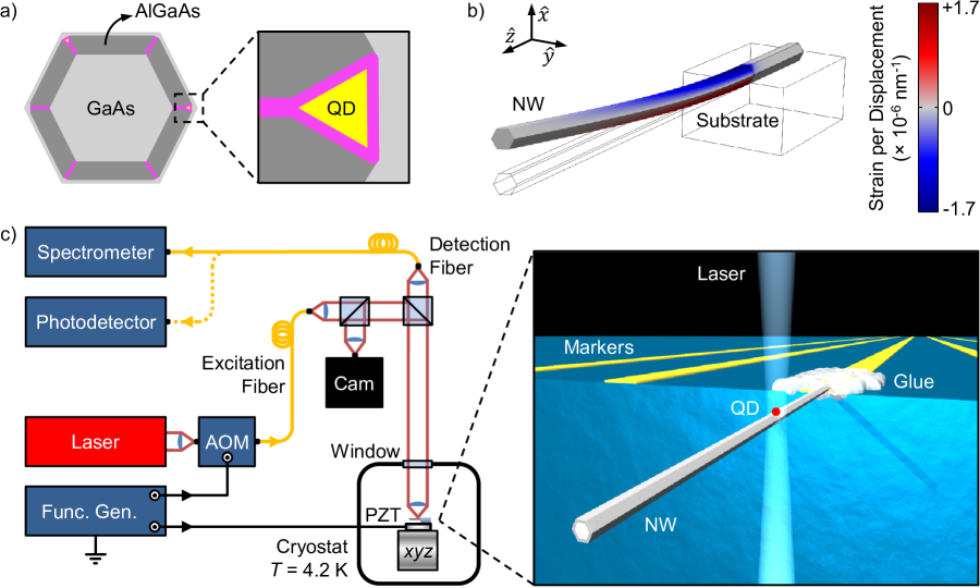
In order to study the opto-mechanical coupling, individual NWs are detached from their growth substrate with micro-manipulators and glued (using an ultra-violet curing adhesive) in a cantilever configuration to the edge of a Si chip, which has been patterned with lithographically defined alignment markers (Ti/Au, 10/30 nm thick). The suspended length of the NWs typically amounts to 20 m. The chip is then rigidly fixed to a piezoelectric transducer (PZT), which is used to excite mechanical oscillations of the NW, as shown in Fig. 1(c). The chip and PZT are mounted to a three-dimensional positioning stage which has nanometer precision and stability (Attocube AG), in a low-pressure 4He chamber ( mbar) at the bottom of a 4He cryostat ( K). The positioning stage allows precise alignment of individual QDs within each NW with the 400-nm collection spot of a confocal optical microscope21 with high numerical aperture (NA ). As shown schematically in Fig. 1(c), the microscope consists of a low-power, non-resonant HeNe excitation laser at 632.8 nm, a camera for imaging the sample, and a high-resolution spectrometer for analyzing the emitted photoluminescence (PL). The mechanical oscillation of each NW is detected via laser interferometry22. W of laser light from a wavelength-tunable, highly coherent 780-nm laser diode are focused onto the NW free end and the reflected light is collected by a fast photodetector. A low-finesse Fabry-Pérot cavity, with a length of cm, forms between the NW and a low-reflective window at the entrance of the 4He chamber, as confirmed by a measurement of its free spectral range. Measurements of the NW displacement by the interferometer are calibrated by an accurate determination of the laser wavelength (for more details, see supporting information).
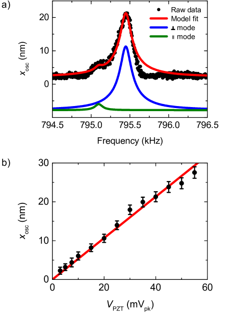
Using the PZT, we excite the fundamental mechanical mode of a NW and detect the resulting oscillations with the interferometer. Fig. 2(a) shows the spectral response of the free-end displacement of the NW. A main resonance and a smaller peak at lower frequency are clearly observable, separated by 350 Hz. The asymmetric clamping of the NW to the Si chip, realized by gluing the NW with one hexagonal facet in contact with the Si surface (see Fig. 1(c)), splits the fundamental mode into a doublet of flexural modes, oriented either perpendicular or parallel to the Si surface. This interpretation is confirmed by a finite element model (FEM) of the experimental system (see supporting information). The mode oscillating perpendicular to the surface is preferentially driven by the PZT, because its oscillation direction coincides with the axis along which the PZT moves. This mode is also more easily detected by the interferometer, since its direction of oscillation coincides with the interferometer optical axis. For these reasons, we interpret the main resonance in Fig. 2(a) as corresponding to the perpendicular mode. The asymmetry visible in this resonance is due to the onset of a weak mechanical non-linearity of the NW 23. When excited in the linear regime, each of these mechanical resonances can be modeled as a driven, dissipative, harmonic oscillator24. Fitting the NW response using this model, we extract for the perpendicular mode a resonant frequency kHz and a mechanical quality factor and for the parallel mode . Furthermore, by driving the main resonance as a function of the excitation amplitude , we explore the linear regime of the NW’s free-end displacement, as shown in Fig. 2(b). With a linear fit, we extract a conversion factor, nm/mV, between the PZT drive amplitude and the amplitude of the free-end displacement.
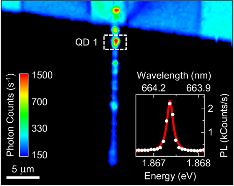
We study the opto-mechanical coupling by collecting PL from individual QDs within a single NW. QDs in proximity of the clamped end of the NW have the largest energy modulation, since the oscillation-induced material strain is highest in this area (Fig. 1(b)). Using the scanning confocal microscope, a number of suitable QDs are identified near the clamped NW end, having bright, narrow, and spectrally isolated exciton emission lines. Fig. 3 shows a spatial map of the PL at 1.867 eV (664 nm) under non-resonant laser excitation of the sample. The plot also includes a weak component of reflected light at the filtered energy, which reveals the position of the NW and the Si substrate with its alignment markers. The map highlights a conveniently located QD, which we label QD 1, whose PL spectral signature includes an exciton emission peak, shown in the inset. In the next step, the laser beam is maintained in alignment with QD 1’s position and its PL spectrum is recorded as a function of the PZT excitation frequency , while holding the amplitude constant. As shown in Fig. 4(a), several emission peaks are detected within the same laser detection spot. As is swept through the NW resonance , the exciton emission peaks are broadened and deformed as a consequence of the time-integrated sinusoidal motion of the NW13. The envelope of the PL spectra as a function of resembles the NW displacement spectrum shown in Fig. 2(a). In particular, the low-frequency shoulder of the broadened envelope corresponds to the oscillation mode parallel to the Si surface.
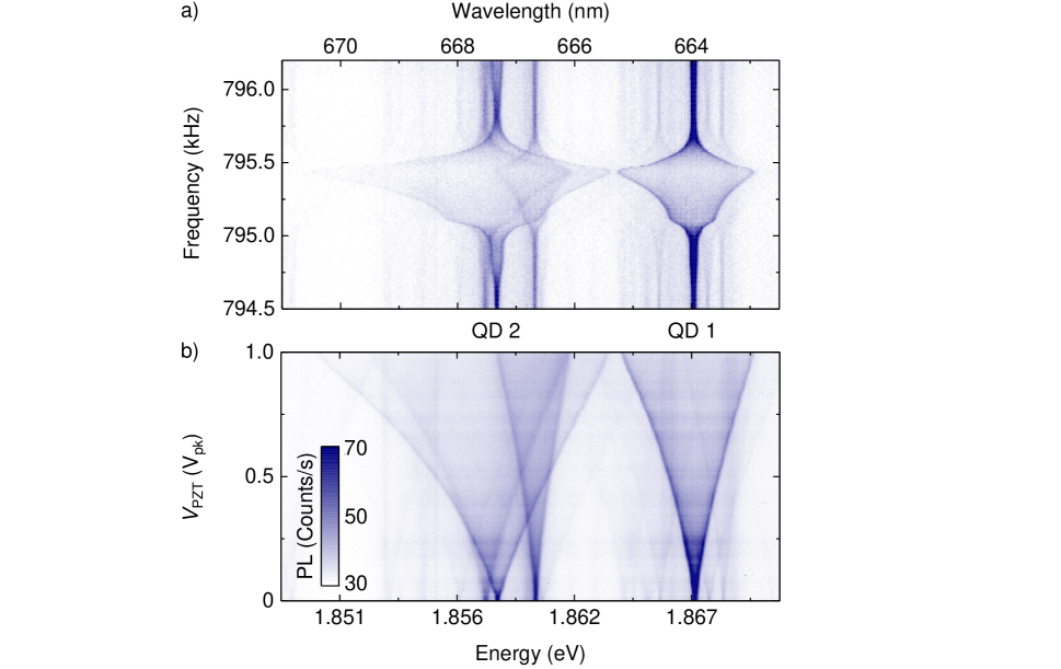
We explore the range of the exciton energy modulation by recording PL spectra as a function of the excitation amplitude , while driving the NW on resonance with the dominant perpendicular mode (). As shown in Fig. 4(b), each spectral line exhibits a different broadening, as a consequence of its specific sensitivity to the local strain. For high excitation voltages, we observe an asymmetric energy broadening, due to the different response of the QD band structure under compressive or tensile stress in the NW25, 26. Note that a further increase of the excitation amplitude leads to a saturation of the peak-to-peak exciton modulation width just beyond 14 meV. It is currently not known whether this modulation is limited merely by how hard we are able to drive the NW motion, or whether a more fundamental saturation eventually limits the range.
While the mechanical motion of the NW in this experiment is best described in classical terms, individual PL peaks from an embedded QD can be approximated as resulting from a quantum two-level system with an exciton transition energy between ground and excited states and 17. The coupling between the NW motion and the QD can then be introduced as a shift in the exciton energy that depends on the displacement of the NW’s free end. Considering only the prominent perpendicular flexural vibration and neglecting non-linear terms in (as in Ref. 4), the time-dependent Hamiltonian of our hybrid system can be written as:
| (1) |
where the first two terms describe the mechanical energy of the unperturbed NW, the third term describes the emission energy of the unperturbed QD, and the last one describes the opto-mechanical interaction. In the equation, is the NW motional mass, is the transition energy of a QD exciton for the NW at its rest position, is the Pauli operator of the two-level system, and is the opto-mechanical coupling parameter at the NW rest position. The NW motion produces a time-varying deformation of the NW’s crystalline structure, in turn altering the energy levels of the embedded QD via a deformation potential, and resulting in a time-varying shift in the QD exciton emission energies. The sign and magnitude of this shift under compressive or tensile strain depend on the localization of the QD within the NW cross section and possibly on intrinsic properties of each QD 27.
To evaluate the strength of the opto-mechanical coupling, we extract the PL profiles of the exciton lines for various values of the drive , e.g. Fig. 5(a). The profiles are then fit with a Lorentzian whose central energy is modulated by a sinusoid of amplitude 14. Using our interferometer measurements (Fig. 2(b)), we then relate the displacement amplitude of the NW free end with the amplitude . The result, displayed in Fig. 5(b) for QD 2 (which resides in the same optical spot as QD 1), shows that in the linear regime of mechanical excitation, is also linear in . A fit to this data provides an opto-mechanical coupling parameter eV/nm, which is one of the largest observed in our measurements.
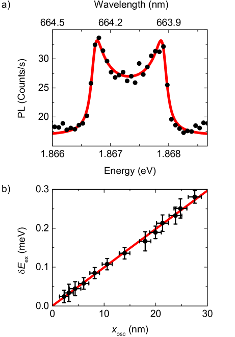
The energy shift of a QD exciton can be modeled by considering the strain-dependent band structure of a semiconductor 28, 29. The deformation potentials and Poisson ratio have been recently measured in an experiment on Zinc-Blende GaAs/AlGaAs core/shell NWs grown along 26. These parameters and a FEM of the NW strain tensor at the position of the QD in question have been used to estimate the displacement-dependent energy shift. The result of eV/nm is in agreement with our measurement and corroborates the strain-dependence of the band structure as the dominant coupling mechanism (see supporting information).
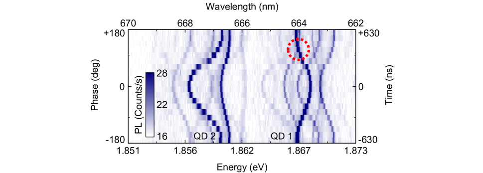
We study the time evolution of the QD exciton energy shift by acquiring stroboscopic PL spectra. Two synchronized and isochronous signals drive the NW on resonance through the PZT and, using an acousto-optic modulator (AOM), chop the laser excitation with a duty-cycle. The QDs are therefore excited only for of the mechanical oscillation period of the NW. By recording PL spectra as a function of the phase between the two modulation signals, as shown in Fig. 6, we explore the temporal evolution of the QD exciton lines during a NW oscillation period. This experiment reveals exciton lines, such as those of QD 1 and QD 2 in Fig. 6, that respond to the mechanical oscillation of the NW with opposite shifts in emission energy. The shifts in energy induced by strain are a consequence of the change in the fundamental bands resulting from the compression or extension of the lattice constant. Therefore, for a given strain, exciton transitions from the same QD should show energy shifts of the same sign and similar magnitude. Conversely, emission lines showing drastically different shift amplitudes or even shifts with different signs correspond to QDs located at different positions within the NW cross-section. In particular, two identical QDs within the same optical collection spot, located on opposite sides of the NW neutral axis, result in opposing strains produced for the same cantilever free-end displacement. On the other hand, differences in the extension and composition of each QD may also account for the varying responses to NW motion 27. In either case, when two spatially and spectrally close QD excitons display strong opto-mechanical couplings of opposite sign, their energies may become degenerate for a particular time in the oscillation period (or equivalently for a particular position of the NW free end), as for the spectral lines outlined by the dashed circle in Fig. 6. In the future, exploiting this mechanically mediated tuning may allow us to couple two nearby QDs within a single NW. In addition, the sinusoidal time evolution of the PL spectral lines emerging from the measurement provides a confirmation of the mechanical origin of the QD emission broadening. Note that the modulation of the QD energy has no measurable influence on the corresponding PL intensity.
In order to compare our results with other hybrid quantum systems4, 13, the opto-mechanical interaction described in Eq. 1 can also be expressed in terms of the coupling rate
| (2) |
which is the exciton frequency shift per vibrational quantum. Here, is the NW’s zero-point motion at its free end and is Planck’s constant. Using the FEM of the NW, we calculate its motional mass , which – combined with knowledge of – allows us to calculate m. Therefore, for QD 2, the coupling rate kHz. This opto-mechanical coupling rate is similar to that recently measured by Yeo et al.13 for etched nano-pillars containing self-assembled QDs, where kHz (note that in Ref. 13 ).
Both here and in Yeo et al., the ratio is not far from unity, which makes these kinds of systems particularly promising for the quantum non-demolition (QND) readout of a QD state through a precise measurement of the NW displacement 13. In particular, using Eqs. 1 and 2, we find that the displacement between the rest positions of the NW free end in the QD states and is . This displacement, in order to be observable, must be larger than ; in fact, at a finite temperature , the displacement must be larger than the NW’s thermal fluctuations . This implies that a determination of the QD state can be made through a displacement measurement, if , where is the average phonon occupation number of the NW’s fundamental mode. In the high temperature limit , the requirement is that , where is the Boltzmann constant. However, for our experimental parameters, the ratio is still times too small for such effects to be observed.
Auffeves and Richard 30 have recently proposed an alternative approach to such a non-demolition measurement, which takes advantage of the high of the NW oscillator. In their scheme, the QD is optically excited by a continuous-wave laser modulated at the NW resonance frequency. This process builds up, through constructive interference, a large coherent mechanical excitation of the NW. On resonance with a QD transition, the amplitude of the excitation is roughly times larger than the displacement difference calculated in the aforementioned static case. For our experimental parameters, this amplitude would be 6 times larger than the NW thermal fluctuations, making it detectable by a high-sensitivity interferometer31. It should be noted that a QND measurement also requires the time necessary to build up such a coherent phonon field () to be smaller than the quantum transition lifetime (), which is not the case here ( ms, while ns) nor in the experiment of Yeo et al.13. The use of a longer-lived QD state such as a dark exciton (s 32) or a spin state ( s 33) could bring the system closer to the required lifetime. In addition, given a detection of the NW displacement with a large enough signal-to-noise ratio, could be reduced using feedback damping, which can modify a mechanical oscillator’s response time without affecting its intrinsic properties34.
We note that prospects of quantum control over a mechanical resonator, or proposals for using a mechanical resonator as a transducer for quantum information, require the hybrid interaction to be large compared to the rates at which the coupled systems decohere into their local environments 35. Some proposals require the condition of “large cooperativity”36, 37: , where is the decoherence rate of the quantum transition, in our case associated to a QD exciton ( GHz17) and is the mechanical heating rate. The cooperativity in this experiment is . Nevertheless, the QD-in-NW system is particularly promising given that could be improved by a factor 2 (or bigger) by driving the NW at its second order (or higher) flexural mode (see supporting information). Assuming that the experiment can be carried out in a dilution refrigerator at mK and that the mechanical can be improved to a few times – perhaps by surface treatment, as was demonstrated in Si cantilevers with similar aspect ratios38– the large cooperativity limit would then become accessible.
In summary, we demonstrate an “as-grown” opto-mechanical system produced entirely by bottom-up self-assembly. The structure’s intrinsic properties couple multiple QDs to the same NW mechanical oscillator. This interaction enables the tuning of QD energies over a broad range exceeing 14 meV, opening the way for mechanically induced coupling between different QDs in the NW. The sensitivity of the QDs in our system to the resonant vibration of the NW could also be used to reveal variations in the mechanical resonance frequency due to the application of electrical or magnetic forces or to a change of the mass of the NW. This fact opens the perspective of using our QD-in-NW system as an integrated force probe or as a nanomechanical mass sensor. By measuring the QD PL, one could monitor the NW motion in a technically simpler way than optical interferometry 31, 39, 40, 41 or other schemes42, 43, 44.
0.1 Supporting Information Available
The mechanical properties of the NW, the effect of strain on the QD-in-NW exciton energy, and the interferometer calibration are discussed in detail. This material is available free of charge via the Internet at http://poggiolab.unibas.ch/full/NWQDSuppInfo.pdf.
0.2 Author Contributions
M.Mo., Y.F., A.F.M., and M.P. conceived the experiment. E.R.A., M.H., and A.F.M. synthesized the NWs. G.W. and R.W. designed and set up the confocal scanning microscope. M.Mo., G.W., and M.Mu. performed the measurements, under the supervision of M.P. and R.W.. M.Mo. analyzed the data and performed the FEM simulations. M.Mo and M.P. wrote the manuscript. All authors discussed the results and contributed to the manuscript.
0.3 Acknowledgements
The authors thank Dr. Jean Teissier and Dr. Fei Xue for fruitful discussion and Dr. Pengfei Wang, Benedikt E. Herzog, Dennis P. Weber, Andrea Mehlin, and Davide Cadeddu for technical support. We acknowledge support from the Canton Aargau, the Swiss NSF (Grant No. 200020-140478), the National Center of Competence in Research for Quantum Science and Technology (NCCR-QSIT), the D-A-CH program of the Swiss NSF (Grant No. 132506), the ERC Starting Grant UpCon, and the ERC Starting Grant NWScan (Grant No. 334762).
References
- Teufel et al. 2011 Teufel, J. D.; Donner, T.; Li, D.; Harlow, J. W.; Allman, M. S.; Cicak, K.; Sirois, A. J.; Whittaker, J. D.; Lehnert, K. W.; Simmonds, R. W. Nature 2011, 475, 359–363
- Chan et al. 2011 Chan, J.; Alegre, T. P. M.; Safavi-Naeini, A. H.; Hill, J. T.; Krause, A.; Gröblacher, S.; Aspelmeyer, M.; Painter, O. Nature 2011, 478, 89–92
- O’Connell et al. 2010 O’Connell, A. D.; Hofheinz, M.; Ansmann, M.; Bialczak, R. C.; Lenander, M.; Lucero, E.; Neeley, M.; Sank, D.; Wang, H.; Weides, M.; Wenner, J.; Martinis, J. M.; Cleland, A. N. Nature 2010, 464, 697–703
- Treutlein et al. 2012 Treutlein, P.; Genes, C.; Hammerer, K.; Poggio, M.; Rabl, P. arXiv:1210.4151 2012,
- Rabl et al. 2010 Rabl, P.; Kolkowitz, S. J.; Koppens, F. H. L.; Harris, J. G. E.; Zoller, P.; Lukin, M. D. Nature Physics 2010, 6, 602–608
- Kolkowitz et al. 2012 Kolkowitz, S.; Bleszynski Jayich, A. C.; Unterreithmeier, Q. P.; Bennett, S. D.; Rabl, P.; Harris, J. G. E.; Lukin, M. D. Science 2012, 335, 1603–1606
- McGee et al. 2013 McGee, S. A.; Meiser, D.; Regal, C. A.; Lehnert, K. W.; Holland, M. J. Physical Review A 2013, 87, 053818
- Palomaki et al. 2013 Palomaki, T. A.; Harlow, J. W.; Teufel, J. D.; Simmonds, R. W.; Lehnert, K. W. Nature 2013, 495, 210–214
- Anetsberger et al. 2010 Anetsberger, G.; Gavartin, E.; Arcizet, O.; Unterreithmeier, Q. P.; Weig, E. M.; Gorodetsky, M. L.; Kotthaus, J. P.; Kippenberg, T. J. Physical Review A 2010, 82, 061804
- Bochmann et al. 2013 Bochmann, J.; Vainsencher, A.; Awschalom, D. D.; Cleland, A. N. Nature Physics 2013, 9, 712–716
- Armour et al. 2002 Armour, A. D.; Blencowe, M. P.; Schwab, K. C. Physical Review Letters 2002, 88, 148301
- Camerer et al. 2011 Camerer, S.; Korppi, M.; Jöckel, A.; Hunger, D.; Hänsch, T. W.; Treutlein, P. Physical Review Letters 2011, 107, 223001
- Yeo et al. 2014 Yeo, I.; de Assis, P.-L.; Gloppe, A.; Dupont-Ferrier, E.; Verlot, P.; Malik, N. S.; Dupuy, E.; Claudon, J.; Gérard, J.-M.; Auffèves, A.; Nogues, G.; Seidelin, S.; Poizat, J.-P.; Arcizet, O.; Richard, M. Nature Nanotechnology 2014, 9, 106–110
- Arcizet et al. 2011 Arcizet, O.; Jacques, V.; Siria, A.; Poncharal, P.; Vincent, P.; Seidelin, S. Nature Physics 2011, 7, 879–883
- Teissier et al. 2014 Teissier, J.; Barfuss, A.; Appel, P.; Neu, E.; Maletinsky, P. arXiv:1403.3405 2014,
- Ovartchaiyapong et al. 2014 Ovartchaiyapong, P.; Lee, K. W.; Myers, B. A.; Bleszynski Jayich, A. C. arXiv:1403.4173 2014,
- Heiss et al. 2013 Heiss, M. et al. Nature Materials 2013, 12, 439–444
- Uccelli et al. 2011 Uccelli, E.; Arbiol, J.; Magen, C.; Krogstrup, P.; Russo-Averchi, E.; Heiss, M.; Mugny, G.; Morier-Genoud, F.; Nygård, J.; Morante, J. R.; Fontcuberta i Morral, A. Nano Letters 2011, 11, 3827–3832
- Russo-Averchi et al. 2012 Russo-Averchi, E.; Heiss, M.; Michelet, L.; Krogstrup, P.; Nygård, J.; Magen, C.; Morante, J. R.; Uccelli, E.; Arbiol, J.; Fontcuberta i Morral, A. Nanoscale 2012, 4, 1486–1490
- Heigoldt et al. 2009 Heigoldt, M.; Arbiol, J.; Spirkoska, D.; Rebled, J. M.; Conesa-Boj, S.; Abstreiter, G.; Peiró, F.; Morante, J. R.; Fontcuberta i Morral, A. Journal of Materials Chemistry 2009, 19, 840
- Högele et al. 2008 Högele, A.; Seidl, S.; Kroner, M.; Karrai, K.; Schulhauser, C.; Sqalli, O.; Scrimgeour, J.; Warburton, R. J. Review of Scientific Instruments 2008, 79, 023709
- Bruland et al. 1999 Bruland, K. J.; Garbini, J. L.; Dougherty, W. M.; Chao, S. H.; Jensen, S. E.; Sidles, J. A. Review of Scientific Instruments 1999, 70, 3542–3544
- Nichol et al. 2009 Nichol, J. M.; Hemesath, E. R.; Lauhon, L. J.; Budakian, R. Applied Physics Letters 2009, 95, 123116
- Montinaro et al. 2012 Montinaro, M.; Mehlin, A.; Solanki, H. S.; Peddibhotla, P.; Mack, S.; Awschalom, D. D.; Poggio, M. Applied Physics Letters 2012, 101, 133104
- Bryant et al. 2011 Bryant, G. W.; Zieliński, M.; Malkova, N.; Sims, J.; Jaskólski, W.; Aizpurua, J. Physical Review B 2011, 84, 235412
- Signorello et al. 2013 Signorello, G.; Karg, S.; Björk, M. T.; Gotsmann, B.; Riel, H. Nano Letters 2013, 13, 917–924
- Jöns et al. 2011 Jöns, K. D.; Hafenbrak, R.; Singh, R.; Ding, F.; Plumhof, J. D.; Rastelli, A.; Schmidt, O. G.; Bester, G.; Michler, P. Physical Review Letters 2011, 107, 217402
- Chandrasekhar and Pollak 1977 Chandrasekhar, M.; Pollak, F. H. Physical Review B 1977, 15, 2127–2144
- Van de Walle 1989 Van de Walle, C. G. Physical Review B 1989, 39, 1871–1883
- Auffèves and Richard 2013 Auffèves, A.; Richard, M. arXiv:1305.4252 2013,
- Nichol et al. 2008 Nichol, J. M.; Hemesath, E. R.; Lauhon, L. J.; Budakian, R. Applied Physics Letters 2008, 93, 193110
- McFarlane et al. 2009 McFarlane, J.; Dalgarno, P. A.; Gerardot, B. D.; Hadfield, R. H.; Warburton, R. J.; Karrai, K.; Badolato, A.; Petroff, P. M. Applied Physics Letters 2009, 94, 093113
- Bar-Gill et al. 2013 Bar-Gill, N.; Pham, L. M.; Jarmola, A.; Budker, D.; Walsworth, R. L. Nature Communications 2013, 4, 1743
- Poggio et al. 2007 Poggio, M.; Degen, C. L.; Mamin, H. J.; Rugar, D. Physical Review Letters 2007, 99, 017201
- Gröblacher et al. 2009 Gröblacher, S.; Hammerer, K.; Vanner, M. R.; Aspelmeyer, M. Nature 2009, 460, 724–727
- Clerk et al. 2008 Clerk, A. A.; Marquardt, F.; Jacobs, K. New Journal of Physics 2008, 10, 095010
- Hammerer et al. 2009 Hammerer, K.; Aspelmeyer, M.; Polzik, E. S.; Zoller, P. Physical Review Letters 2009, 102, 020501
- Rast et al. 2006 Rast, S.; Gysin, U.; Ruff, P.; Gerber, C.; Meyer, E.; Lee, D. W. Nanotechnology 2006, 17, S189
- Carr and Craighead 1997 Carr, D. W.; Craighead, H. G. Journal of Vacuum Science & Technology B 1997, 15, 2760–2763
- Belov et al. 2008 Belov, M.; Quitoriano, N. J.; Sharma, S.; Hiebert, W. K.; Kamins, T. I.; Evoy, S. Journal of Applied Physics 2008, 103, 074304
- Favero et al. 2009 Favero, I.; Stapfner, S.; Hunger, D.; Paulitschke, P.; Reichel, J.; Lorenz, H.; Weig, E. M.; Karrai, K. Optics Express 2009, 17, 12813–12820
- Treacy et al. 1996 Treacy, M. M. J.; Ebbesen, T. W.; Gibson, J. M. Nature 1996, 381, 678–680
- Montague et al. 2011 Montague, J. R.; Dalberth, M.; Gray, J. M.; Seghete, D.; Bertness, K. A.; George, S. M.; Bright, V. M.; Rogers, C. T.; Sanford, N. A. Sensors and Actuators A 2011, 165, 59–65
- Hoch et al. 2011 Hoch, S. W.; Montague, J. R.; Bright, V. M.; Rogers, C. T.; Bertness, K. A.; Teufel, J. D.; Lehnert, K. W. Applied Physics Letters 2011, 99, 053101