Design of a speed meter interferometer proof-of-principle experiment
Abstract
The second generation of large scale interferometric gravitational wave detectors will be limited by quantum noise over a wide frequency range in their detection band. Further sensitivity improvements for future upgrades or new detectors beyond the second generation motivate the development of measurement schemes to mitigate the impact of quantum noise in these instruments. Two strands of development are being pursued to reach this goal, focusing both on modifications of the well-established Michelson detector configuration and development of different detector topologies. In this paper, we present the design of the world’s first Sagnac speed meter interferometer which is currently being constructed at the University of Glasgow. With this proof-of-principle experiment we aim to demonstrate the theoretically predicted lower quantum noise in a Sagnac interferometer compared to an equivalent Michelson interferometer, to qualify Sagnac speed meters for further research towards an implementation in a future generation large scale gravitational wave detector, such as the planned Einstein Telescope observatory.
pacs:
04.80.Nn, 07.60.Ly, 42.50.Lc1 Introduction
The world-wide network of interferometric gravitational wave (GW) detectors is currently in an upgrade phase towards what is commonly referred to as the second generation of detectors. This detector network is formed of the Advanced LIGO detectors (USA) [1], the Advanced Virgo detector (Italy/France) [2], the GEO-HF detector (Germany/UK) [3] and the new Japanese KAGRA observatory [4]. All of these detectors are based on the classical Michelson topology and will be limited in their sensitivities by quantum noise over a large range of frequencies. Quantum noise originates from the quantum fluctuations of the laser light, which is used for the measurement of GW induced strain, and manifests as quantum radiation pressure noise (QRPN) and shot noise, dominating at low and high frequencies, respectively.
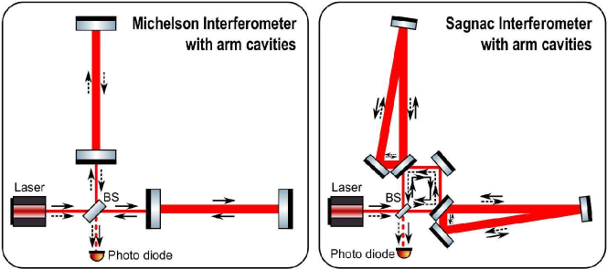
Michelson-based laser interferometers, cf. figure 1, are so called position meters, i.e. the measured observable is the position of the test mass mirrors which does not commute with itself at subsequent moments of time. This non vanishing commutator yields an uncertainty relation for subsequent position measurements which enforces the so-called Standard Quantum Limit (SQL). The notion of the SQL was originally coined by Braginsky [5] and was believed to set a limit to the achievable sensitivity of a precision measurement apparatus. It was later realised by Braginsky that it is in fact possible to overcome the SQL by performing a so-called Quantum Non-Demolition (QND) measurement [6], e.g. by introducing cross-correlations in the quantum noise in an interferometer.
To achieve sensitivities an order of magnitude higher than in the second generation GW observatories [7] requires quantum noise to be reduced. In particular, the characteristic frequency dependence of QRPN causes it to occlude the low-frequency band which contains a rich population of potential sources [8]. An important cornerstone in the designs of GW detectors beyond the second generation, such as the planned Einstein Telescope detector [9], is the use of frequency dependent squeezed vacuum states of light [10]. This technique was, among others, proposed by Kimble et al. [11] and aims for the conversion of conventional Michelson-based GW detectors into QND interferometers, to achieve a broadband improvement of the quantum noise limited sensitivity. However, all the schemes proposed in [11] have in common that they come at the expense of substantially increased technical complexity as they require the adoption of large scale low-loss filter cavities.
A new approach which is based on performing a measurement of an observable which is intrinsically a QND observable, i.e. a conserved quantity, was first introduced to the field of GW interferometry by Braginsky. In so-called speed meters the intention was to measure the momentum of the test masses, for which their relative velocity was thought to be a good proxy [12]. However, a more thorough analysis has shown that in an opto-mechanical system, in which test mass dynamics and light fields are coupled, velocity is not a conserved quantity (see section 4.5.2 of [13] and references therein) and therefore is also limited by the SQL. Nevertheless, the QRPN of the speed meter is naturally reduced. This opens the way for a broadband beating of the SQL using homodyne readout of the optimally chosen light quadrature at the dark port.
The first practical speed meter configurations were based on the concept of signal sloshing [14] and aimed at modifications of the optical layouts of the already well-established Michelson-based configurations, by introducing so-called sloshing cavities in the Michelson output port [15]. In 2003, Chen pointed out that a Sagnac interferometer, cf. figure 1, is a speed meter per se, as the signal exiting the interferometer is proportional to the time-dependent variation of the relative test mass positions, i.e. to their relative velocity [16]. This makes Sagnac interferometers the more favourable speed meter configuration since no additional large scale cavity needs to be included in the optical layout for which ultra-low loss operation and low noise feedback control need to be pioneered.
Sagnac interferometers, in a zero area configuration, had already been studied as candidate configurations for GW detectors more than a decade ago, prior to the implementation of the first generation of large scale detectors [17, 18, 19]. However, these investigations did not reveal significant advantages over Michelson-based configurations because Michelson interferometers were far from being limited by the SQL and the quantum back action evasion potential of Sagnac-based configurations was unknown.
In the scope of the conceptual design study for the Einstein Telescope (ET) third generation GW observatory it was shown that, in theory, Sagnac speed meter interferometers outperform Michelson-based interferometers with comparable parameters in terms of higher broadband sensitivities [20]. This result was recently confirmed by Miao et al. in [21]. Despite the advantages of speed meter configurations, Michelson-based interferometers were chosen as the baseline design for the ET detectors [22]. This choice was to a large extent motivated by the fact that Michelson-based interferometers have been highly refined and optimised for gravitational wave detection over a period of almost four decades.
In the longer term, Sagnac speed meter configurations are prospective candidates for replacing Michelson-based GW detectors. However, the superiority of Sagnac-based configurations is yet to be demonstrated experimentally. Hence, the main objectives of our Sagnac speed meter experiment are i) the realisation of an ultra-low noise, QRPN dominated speed meter test bed and ii) the experimental demonstration of reduced quantum back action noise in comparison to an equivalent Michelson-based interferometer. By reaching these objectives we aim for qualifying the Sagnac speed meter concept for further research towards an implementation in a future GW detector, such as the Einstein Telescope.
2 Conceptual approach
In this section we illustrate the conceptual approach to the Glasgow Sagnac Speed Meter (SSM) experiment design. With this experiment we aim for the demonstration of reduced quantum back-action noise in a Sagnac interferometer in comparison to an equivalent Michelson interferometer. However, it must be noted that beating the SQL, as is aimed for in conceptually similar experiments, as e.g. [23], is not one of the explicit goals of our SSM experiment.
The starting point for the design of our SSM experiment was a conventional Michelson interferometer with Fabry-Perot cavities in the arms, with quantum noise dominating over the total classical noise in the instrument at low frequencies. The low-frequency sensitivity of this Michelson interferometer design then served as a benchmark for the SSM conceptual design, in the sense that a successful equivalent speed meter design needs to yield better low-frequency sensitivity than could be achieved with the reference Michelson interferometer design.
The main drivers in the conceptual design process were i) an optimisation of the design to enhance QRPN and ii) the reduction of classical noise sources which potentially mask quantum noise. To fulfill the former requirement, the ratio of the circulating light power and the arm cavity mirror masses was chosen, to push the frequency at which shot noise and QRPN are equal to above approximately 5 kHz. Here, the challenge is to identify a set of design parameters resulting in sufficiently low classical noise while maintaining the technical feasibility and operability of the experiment. In our case this was achieved by choosing a high arm cavity finesse resulting in circulating powers in the kW range and by choosing a mirror mass for the arm cavity input couplers of approximately one gram. Regarding the test mass and intra-cavity power regimes, our SSM experiment is comparable e.g. to the experiments described in [24, 25]. Generally, to keep the technical complexity of the SSM experiment at a manageable level, the design was to the largest possible extent based on well-established experimental techniques and the adoption of new techniques, i.e. so far untested or immature ones, was avoided where possible.
In contrast to even lighter test masses, such as membranes or cantilevers, our cavity input mirrors have the advantage of lower thermal noise. Also, in this mass regime it is feasible to employ the same concepts of low-dissipation mirror suspension systems as well as actuation schemes as those used in prototype interferometer experiments and full-scale GW detectors. To isolate the experiment from seismic and environmental noise and, at the same time, keep thermal noise at a sufficiently low level, the in-vacuum optics will be suspended using cascaded pendulum suspensions. For the core interferometer optics these will feature multiple eddy-current damped pendulum stages with an all-monolithic final stage for horizontal isolation and cantilever-mounted blade springs for vertical isolation. Additional filtering of seismic disturbances will be provided by a passive stack-type pre-isolation system consisting of four alternating layers of stainless steel mass elements and fluoroelastomer spring elements.
An arm cavity round trip length of approximately 2.83 m was chosen. The short cavity length allows a compact physical arrangement designed to yield good common mode rejection of seismic noise. It also provides low susceptibility to frequency noise, allowing a measurement sensitivity between m and m at frequencies of a few hundreds of Hz. A selection of key design parameters of the SSM experiment is summarised in table 1.
| Parameter | Value |
|---|---|
| Laser source | Nd:YAG NPRO laser, W nm |
| Spatial mode filtering | Single mode optical fibres + triangular pre-mode cleaner cavity |
| Vacuum system | Two vacuum tanks, 1 m diameter, 1.5 m centre-to-centre length |
| Targeted pressure | mbar, dominated by water vapour |
| Operating temperature | Room temperature |
| Lab environment | Class 1000 clean room by design – better performance in measurements; additional clean room tents. |
| Seismic pre-isolation | Passive system with four stack layers, comprised of stainless steel mass elements and Fluorel springs |
| Core optics mass | Arm cavity incoupling mirrors g; arm cavity end mirrors g |
| Core optics suspensions | Triple pendulum suspensions: steel wires in the upper stages, all monolithic final stage. Blade springs for vertical isolation. |
| Fused silica fibres for 1 g mirrors | 20 m diameter, 5 cm length |
| Thermo-elastic peak frequency | 18 kHz () |
| Pendulum Q factor | |
| Suspension control | Eddy current damping, coil-magnet actuators and electro static drives |
| Interferometer configuration | Zero area Sagnac interferometer with high-finesse triangular arm cavities |
| Arm cavity length (round trip) | m ( m) |
| Arm cavity input mirrors | Fused silica, ppm |
| Dielectric mirror coatings | Silica/Tantala double stacks (, ) |
| Arm cavity finesse | 10000 |
| Optical power | 0.3 W at beam splitter, 1 kW in the arms |
| Beam radius on cavity mirrors | 1.12 mm (input mirror); 1.01 mm (end mirrors) |
| Arm cavity round trip loss | 25 ppm |
| Interferometric sensing of auxiliary degrees of freedom | Heterodyne signal readout |
| Main interferometer readout | Balanced homodyne detection with suspended optical local oscillator path |
| Readout quantum efficiency | % |
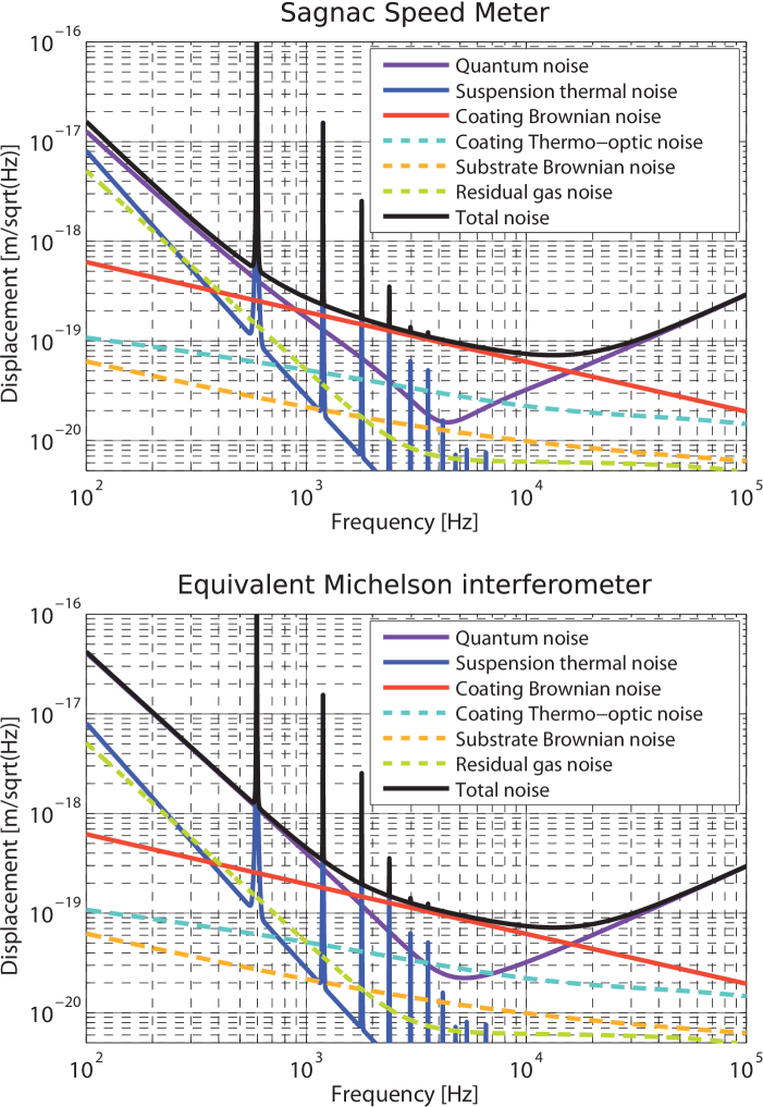
The plots in figure 2 show the noise model of our SSM experiment in comparison to an equivalent Michelson interferometer, including quantum noise [13, 26], thermal noise of the mirror suspensions [27, 28, 29, 30, 31], Brownian noise [32] and thermo-optic noise [33] of the dielectric mirror coatings, Brownian noise of the mirror substrates [34, 35] and optical pathlength noise [36] as well as Brownian force noise due to residual gas in the vacuum envelope [37, 38]. The code architecture of our noise modelling software is based on the interferometer noise modelling tool GWINC [39].
Loss is the enemy of any optical experiment probing at effects which are governed by quantum mechanics. Theory predicts that the net reduction of QRPN in a Sagnac speed meter critically depends on the incurred optical losses [41], in particular on round trip loss inside the arm cavities. Minimal speed meter-type QRPN can only be achieved in an interferometer with perfect, lossless optics. For our experiment we are aiming for a round trip optical loss of equal or less than 25 ppm in each arm cavity and a detection efficiency of the main interferometer signal of better than 95 %. Our estimate of the round trip loss in the arm cavities is based on recent investigations of the feasibility of low loss filter cavities for the generation of frequency dependent squeezed states of light [42, 43] for the broadband quantum enhancement of GW detectors. For the chosen value of 25 ppm per round trip it was taken into account that the arm cavities in our experiment will be triangular ones, formed by three mirrors each, cf. section 3.
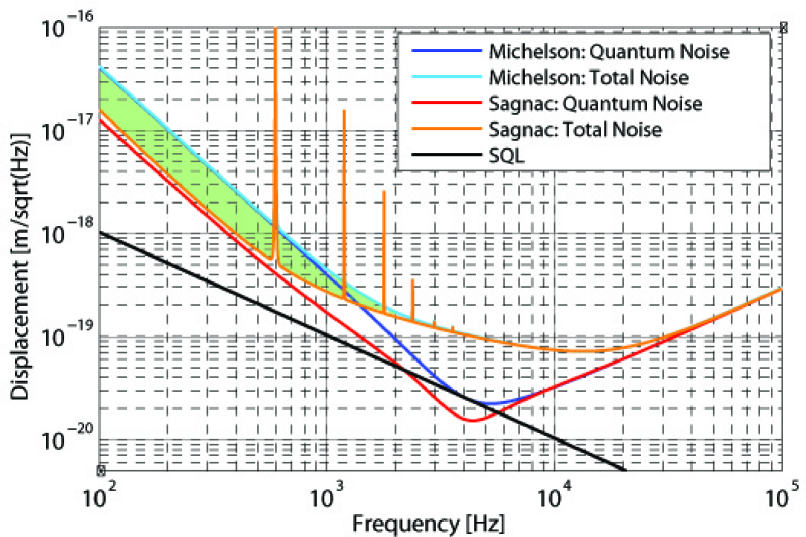
The proposed SSM design achieves the goal of a better sensitivity than an equivalent Michelson-based interferometer at frequencies below approximately 3 kHz. As can be seen in figure 3, at frequencies of hundreds of Hz the Sagnac interferometer outperforms the reference Michelson interferometer by up to a factor of . In our experiment we are aiming to reach a sensitivity within the green shaded region in figure 3, to demonstrate the reduction of QRPN in a Sagnac speed meter. If we assume a slightly lower round trip loss of 20 ppm per cavity the gap between the total noise in the Sagnac and Michelson interferometer increases to a factor of and for a round trip loss of 15 ppm per cavity the gap increases to a factor of . For a slightly higher round trip loss of 30 ppm per cavity the gap is reduced to a factor of .
Note that further increased margin could be provided by reducing coating Brownian noise, which dominates in the measurement band at frequencies above approximately 800 Hz, as can be seen in figure 2. Crystalline coatings were reported to be capable of reducing this noise by a factor of [40]. Although a further reduction of this noise would increase the signal-to-noise ratio in our experiment, it is not crucial to reach our main objective of demonstrating reduced quantum noise at low frequencies.
Once the reduction of quantum back-action noise has been demonstrated it is planned to carry out a detailed experimental study of the influence of optical losses and asymmetries between the arm cavities on the performance of the interferometer. The experimental validation of the predictions made in theoretical models will contribute substantially to the understanding of Sagnac-based interferometer configuration and to laying a foundation for establishing Sagnac speed meters as baseline configurations for future generation GW detectors.
3 Technical realisation of the Sagnac Speed Meter experiment
In this section we present the design of the SSM experiment testbed as well as the optical layout of the core interferometer.
The SSM experiment is currently being set up in the Glasgow interferometer prototype laboratory. The facility was designed to meet class 1000 clean room standards. However, measurements show that a better performance is achieved in practice. To suppress acoustic coupling, residual gas noise and refractive index fluctuations, the whole interferometer will be operated in vacuum. The vacuum system is enclosed in additional clean tents to provide a clean environment for the SSM experiment of class 10 or better, to mitigate the risk of increased optical loss due to contamination of the optical elements. The experiment will be carried out at room temperature and fused silica will be used as the optics’ substrate material throughout.
For the SSM experiment, critical classical noise sources are (i) seismically driven motion of the test mass mirrors, i.e. seismic noise, (ii) Brownian thermal noise of the mirror suspension systems, especially of the suspension fibres, i.e. suspension thermal noise and (iii) Brownian noise of the highly reflective dielectric mirror coatings of the core interferometer optics, i.e. coating Brownian thermal noise.
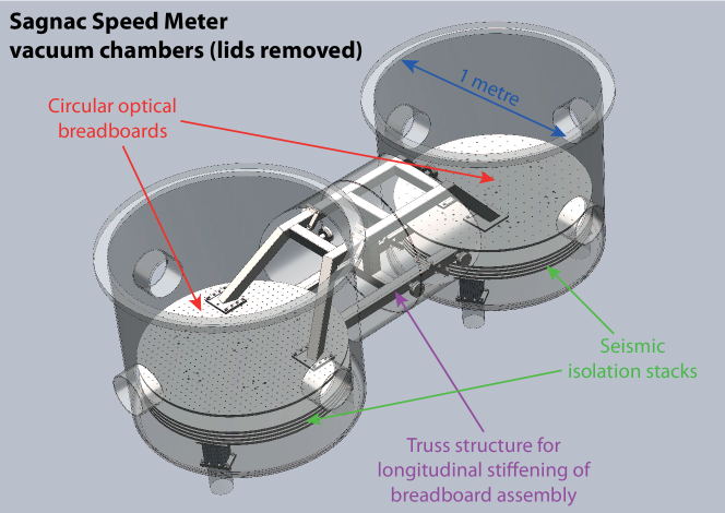
Shielding of the interferometer from seismic motion of the ground is achieved with a stack-type pre-isolation system in combination with multi-stage cascaded pendulum mirror suspensions. For the seismic isolation platforms, a passive multi layer stack consisting of alternating layers of fluoroelastomer springs and circular stainless steel mass elements was adopted. With our 4-layer stack system we aim for vertical resonance frequencies around 18 Hz and a suppression of seismic motion of more than 60 dB at frequencies above 200 Hz. Additionally, the two circular optical platforms supporting the mirror suspensions will be connected and stiffened with a truss structure, in order to ensure rigid motion of both platforms at low frequencies. A rendered image of the vacuum enclosure, seismic pre-isolation system and optical tables is shown in figure 4.
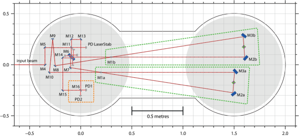
All mirrors inside the vacuum system, including the main beam splitter of the Sagnac interferometer, the arm cavity mirrors as well as numerous steering mirrors, will be suspended with cascaded pendulum suspensions. An overview of the in-vacuum optical layout is shown in figure 5. The designs of the suspensions used in our SSM experiment are conceptually similar to the designs used in large scale GW interferometers [44] and range from simple metal wire suspensions of the steering mirrors to triple pendulum suspensions with an all-monolithic final stage for input and end mirrors of the arm cavities. However, low mass mirrors substantially complicate the task of designing low-dissipation suspensions, e.g. due to a higher significance of surface loss as a consequence of a high surface-to-volume ratio on the one hand and cross couplings due to the smaller scale and the effects of fabrication tolerances on the other hand.
With these suspensions we aim for lower thermal noise than was observed in foregoing experiments with similar mirror masses. A key element of the core optics suspensions will be m – m diameter fused silica fibres, which have recently become feasible to be manufactured due to advances in precision controlled fibre production at Glasgow. It is planned to utilise the fibre pulling and welding techniques and infrastructure developed for the Advanced LIGO monolithic suspensions [45, 46], albeit on a much smaller scale. For our noise model a value of was assumed for the pendulum quality factor which results in sufficiently low suspension thermal noise in the SSM experiment, cf. section 2. The stress of the fibres for the one gram mirror suspension was calculated to be approximately a factor of 500 below the breaking strength of fused silica.
The optical layout of the SSM experiment needs to fulfill two crucial requirements to ensure compatibility with the target sensitivity. First, the influence of coating Brownian thermal noise needs to be reduced below quantum noise level, which will be achieved with state-of-the-art Titania-doped SiO2/Ta2O5 multilayer coatings [32], in combination with large laser beam spots on the highly reflective test mass surfaces [47]. Second, the optical setup needs to be designed to ensure sufficient stability of the optical cavities with gram-scale mirrors at circulating powers in the kW range. Whereas for initial experiments it is aimed for optical powers in the arm cavities of approximately one kW, this value may be increased towards several kW in subsequent experiments.
For the SSM experiment we have chosen to employ triangular arm cavities as a straightforward approach to separating the incoming from the outgoing laser beam at the cavity input mirrors, cf. figure 5. Alternatively, beam separation can be achieved e.g. by making use of different polarisation states of the fields incident and returning from the arm cavities [48], which is traditionally referred to as a “polarisation Sagnac” configuration and has been proposed as a candidate QND configuration for Advanced LIGO [41] and for the Einstein Telescope GW observatory [49]. However, despite potentially increased cavity round trip loss in the configuration with triangular arm cavities, due to the increased number of mirrors per cavity by one, the polarisation Sagnac configuration was not chosen for our experiment to avoid the risk of performance limitations associated with limited extinction of polarising optics.
Each of the two arm cavities will be formed by a curved one gram input mirror (M1a/b in figure 5) and two planar 100 g end mirrors (M2a/b, M3a/b) with diameters of mm and mm, respectively. Thus, for a given round trip length of the cavities the eigenmode geometry is fully determined by the radius of curvature (ROC) of the input mirror. The dependence of beam spot radii on the cavity mirrors and the buildup of higher order transverse modes (HOMs) on the input mirror ROC is illustrated in figure 6. For the input mirror ROC a value of 7.91 m was chosen which leads to beam spot radii mm on all cavity mirrors. Assuming a clear aperture radius of the arm cavity input mirrors of mm and beam spot radii of mm on the input mirrors, cf. left plot in figure 6, HOMs up to approximately 12th order will resonate inside the cavities with relatively low losses [51]. Our chosen value for the input mirror ROC results in a comparatively low resonant buildup of low order HOMs in the arm cavities, cf. right plot in figure 6, which could otherwise limit the performance of the experiment. Based on the generalised approach detailed in [52], our triangular arm cavity design exhibits geometric stabilities of in the tangential plane and in the sagittal plane, which were obtained from the propagation matrices describing one full cavity round trip.

Arranging for beam spots larger by a factor of would require an input mirror ROC of approximately 100 m which came at the expense of a strongly reduced geometric stability and potentially lower robustness to misalignment of the cavities. Furthermore, taking the free aperture radius of the arm cavity input mirrors of mm into account, beam spots with a radius of 2 mm or larger are prone to substantially increased scattering and diffraction loss. To mitigate these losses the diameter of the arm cavity input mirrors could be increased. However, to maintain the same ratio of beam spot radius to clear aperture radius, while also maintaining the same substrate aspect ratio optimised for low thermal noise [53], an increase of the beam spot radius by a factor of two would result in an 8-fold increase of the mirror mass. As a consequence this would require a substantial increase of the circulating laser power to reach the same level of quantum back-action noise as in the configuration with smaller beam spots.
Further important drivers for the design of the optical layout of our experiment are the requirement to ensure optimal mode matching of the two arm cavities, sufficient means of optimising the angular alignment of the interferometer as well as optimal beam overlap at the balanced homodyne detector (cf. section 4), to keep optical detection losses at a minimum. For the planned geometry of the triangular SSM arm cavities, calculations based on the model presented in [55] have shown that the intrinsic astigmatism results in a degradation of the theoretically achievable mode matching efficiency in the sub-ppm range. This result was confirmed in numerical simulations of the arm cavities. Hence, no significant impact on the balanced homodyne detector contrast is expected. However, if the signal field leaving the interferometer turned out to be more astigmatic than expected, an astigmatic LO beam could be employed to recover the homodyne contrast.
The input laser beam, coming from the left in the drawing in figure 5, is directed into the vacuum tank and propagates towards the main 50/50 beam splitter (denoted M6) where the beam is split equally and guided into the two arm cavities. Mode matching to the arm cavities with a beam waist located between the far mirrors M2a, M3a and M2b, M3b, respectively, is achieved with a mode matching telescope outside vacuum. The cavities will be mode matched among each other with the aid of a curved steering mirror labelled M9 in the drawing. For this mirror, a small angle of incidence was chosen to avoid distortion of the reflected beam. For beam steering and auxiliary optics, mirrors with a diameter of 30 mm will be used. For the main beam splitter, M6, a diameter of 80 mm was chosen, to allow better control of AR and secondary reflections.
The bright port of the Sagnac interferometer was chosen as the source of the local oscillator (LO) field for balanced homodyne detection. In contrast to picking off a fraction of the input beam or, alternatively, light reflected from the AR coating of the main beam splitter [56], the beam exiting the bright port of the interferometer is easily accessible and exhibits the same wave front curvature as the signal beam, i.e. the two fields can be superimposed without the need for additional focussing elements in one of the beam paths. Longitudinal and angular degrees of freedom of the LO field and the signal field can be actuated upon with the mirrors M12, M13 and M14, M15, respectively. Approximately 10 mW of laser light are planned to be picked off for the LO beam. However, if requirements change in the course of our experiment, the LO power can be adjusted by swapping mirrors in the optical layout with ones with different reflectivity. Besides the mirror M11, whose transmittance also determines the laser power reaching the in-vacuum photo diode for laser amplitude stabilisation, the transmittances of the mirrors M12 and M13 in the LO path can be adjusted to provide independence of the LO power from the power of the light picked off for laser stabilisation.
Similar to the Michelson-based interferometers used in GW detection our SSM interferometer will require feedback control of various longitudinal and angular degrees of freedom in the optical setup, to ensure maximisation of resonant light buildup and minimisation of noise couplings to the signal port of the interferometer. We are planning to take the same technical approach currently employed in Michelson-based large and small scale interferometers, i.e. heterodyne signal extraction based on frontal phase modulation in conjunction with the well-known Pound-Drever-Hall technique [57]. To allow for flexibility in the control scheme of the interferometer it is planned to include actuators in all core optics suspensions. Coil-magnet type actuators in combination with electrostatic drives will serve to actuate on the relevant longitudinal and angular degrees of freedom of the core optics. A new type of electro-static actuator, similar to the design used in the AEI 10 m Prototype [58], is planned to be used for direct actuation on the low mass arm cavity input mirrors. Longitudinal and angular control is planned for the two arm cavities, the balanced homodyne detector and, if needed, also for the optical path lengths in the central Sagnac interferometer and the path of the beams travelling from the first to the second arm cavity. The main calibrated output signal in the SSM experiment will be obtained from the balanced homodyne detector. Detailed numerical investigations to inform the final interferometric sensing and controls system design are currently underway.
4 Experimental challenges
In many respects, the SSM experiment will require existing and well-established interferometry concepts to be pushed to their limits and, moreover, it will be necessary to adopt techniques which have not yet been practically implemented and tested under comparable circumstances. In this section we discuss some experimental challenges which we expect to face in the course of the construction and operation of the SSM experiment.
4.1 Radiation pressure-dominated test mass dynamics
The SSM will be operated in a regime in which the test mass dynamics are dominated by radiation pressure effects. The combination of light mirrors and moderately high circulating optical power is expected to drive longitudinal and angular optical springs, formed due to radiation pressure during lock acquisition and in the locked interferometer, to higher frequencies than e.g. in full-scale GW detectors. This will require the development of new lock acquisition strategies and improved control schemes to keep the interferometer optics at their designated operating points.
Longitudinal optical springs occur in detuned cavities and change the dynamics of the experiment by opto-mechanical coupling. To maintain control over the affected resonators, actuators with sufficiently large actuation range are required. With multi-stage suspensions it would be preferable to actuate on one of the upper masses, thus benefiting from the filtering of actuator noise by the pendulum stages. This, on the other hand implies that actuation only at low frequencies will be possible, due to the low pass filter characteristic of the pendulum stages. Optical springs in the kHz range may require direct actuation on the test mass for compensation which would require the use of very low noise actuators. However, the occurrence of optical springs during lock acquisition may be mitigated with the aid of a special tailored lock acquisition scheme, e.g. the transition of the experiment to the targeted high-power state of operation after lock acquisition at lower optical power.
For the effect of radiation pressure-induced angular optical springs it was shown that these can be mitigated by adopting a suitable arm cavity design [59] and by means of appropriate angular feedback control [60]. The latter approach, however, is known to be challenging to realise for angular springs ocurring at high frequencies due to large required control bandwidths. Theoretical investigations of angular instabilities in the triangular cavities in the LIGO interferometers showed that for a geometrically stable cavity the angular modes in the horizontal plane, i.e. in yaw, are always intrinsically stable [61]. This property was confirmed experimentally in [62]. In the same article the authors propose a new approach to reduce suspension thermal noise in interferometric weak force measurements which is based on using triangular cavities, which do not require angular control in yaw due to the aforementioned effect, and single-wire mirror suspensions. Although this approach may offer reduced low frequency thermal noise, for the SSM experiment the standard approach offering the possibility of full angular control of the mirrors will be taken, to avoid relying on new, less mature techniques where possible.
4.2 Main interferometer signal readout
The fact that in a Sagnac interferometer the light returning from the arms always interferes destructively at the signal port, regardless of any microscopic offsets, has implications on the effectiveness of sensing and control schemes. On the one hand, this property reduces, by one, the number of length degrees of freedom in the interferometer that require feedback control to keep the instrument on its nominal operating point [17, 63]. On the other hand, this effect renders the DC readout scheme, which is the standard method of reading out the main interferometer signal in second generation GW detectors [64, 65, 66], unsuitable for our experiment. For this reason it is planned to utilise balanced homodyne detection in the SSM experiment, cf. section 2.
In balanced homodyne detection, other than in the DC readout scheme, an external optical LO field is superimposed on a beam splitter with the field exiting the signal port of the interferometer, which allows the selection of an arbitrary readout quadrature by tuning the relative phase of the LO and signal field accordingly [67]. It is an intrinsic property of balanced homodyne detectors that common-mode noise is suppressed. By careful fine tuning of the optical and electronic balancing, common mode rejection ratios of up to approximately 80 dB have been consistently achieved [68]. Even though balanced homodyne detection is an established and well-understood tool in bench-top quantum optics experiments, it has not yet been employed for reading out suspended interferometers at audio frequencies. It is expected that the frequency stability of the LO field will be crucial to read out displacement noise down to the m/ level.
Also, carrier light leaking from within the interferometer into the detection port may give rise to additional readout noise due to a reverse homodyning effect, by acting as an unwanted second local oscillator at the balanced homodyne detector. In the SSM experiment the level of carrier leakage will strongly depend e.g. on the beam splitting ratio of the main Sagnac beam splitter. Since any attempt of attenuating the beam exiting the interferometer towards the balanced homodyne detector will introduce additional optical losses, it will be necessary to control carrier leakage by formulating sufficiently stringent tolerances for the relevant core optics parameters.
Detailed investigations of aspects such as the impact of LO noise and carrier light leakage on the performance of the planned balanced homodyne detection scheme are currently ongoing, experimentally as well as theoretically. Optionally, heterodyne readout schemes which are less susceptible to low-frequency noise may be considered as alternatives.
5 Summary and Outlook
In this article we have presented a conceptual design for a speed meter proof-of-principle experiment. The construction of the experiment is well under way, with the vacuum system and the seismic pre-isolation completed. Next steps will include, amongst others, a detailed analysis of the relation of asymmetric optical losses in the various sections of the interferometer and their influence on quantum noise [26], the technical design of the multi-stage suspension system for the one gram mirrors as well as the design of a longitudinal and angular sensing and control scheme for the interferometer, including detailed control noise studies.
The experimental demonstration of the reduction of quantum back-action noise in a Sagnac speed meter interferometer is expected to have significant impact on the field of ultra-high precision interferometery and will be the first step towards qualifying Sagnac topologies as baseline interferometer designs for future generation GW observatories such as the Einstein Telescope.
References
References
- [1] G M Harry for the LIGO scientific collaboration, Class. Quantum Grav. 27, 084006 (2010)
- [2] The Virgo collaboration, Class. Quantum Grav. 28, 114002 (2011)
- [3] H Grote and the LIGO Scientific Collaboration, Class. Quantum Grav. 27, 084003 (2010)
- [4] Y Aso et al for the KAGRA collaboration, Phys. Rev. D 88, 043007 (2013)
- [5] V B Braginsky and F Ja Khalili, Quantum Measurement (Cambridge University Press, Cambridge; New York, 1992)
- [6] V B Braginsky et al., Science 209, 547-557 (1980)
- [7] M Punturo et al., Class. Quantum Grav. 27, 084007 (2010)
- [8] B Sathyaprakash et al., Class. Quantum Grav. 29, 124013 (2012)
- [9] M Punturo et al., Class. Quantum Grav. 27, 194002 (2010)
- [10] S Hild et al., Class. Quantum Grav. 28, 094013 (2011)
- [11] H J Kimble et al., Phys. Rev. D 65, 022002 (2001)
- [12] V B Braginsky and F Ja Khalili, Phys. Lett. A 147, 251–256 (1990)
- [13] S L Danilishin and F Ya. Khalili, Living Rev. Relativity 15, (2012)
- [14] V B Braginsky et al., Phys. Rev. D 61, 044002, (2000)
- [15] P Purdue and Y Chen, Phys. Rev. D 66, 122004, (2002)
- [16] Y Chen, Phys. Rev. D 67, 122004 (2003)
- [17] K-X Sun et al., Phys. Rev. Lett. 76, 3053 (1996)
- [18] D A Shaddock, Appl. Opt. 37, 7995 (1998)
- [19] P T Beyersdorf et al Class. Quantum Grav. 19, 1585 (2002)
-
[20]
H Müller-Ebhardt et al.,
“Review of quantum non-demolition schemes for the Einstein Telescope,”
ET-010-09 (2009), available online at
https://tds.ego-gw.it/itf/tds/file.php?callFile=ET-010-09.pdf - [21] H Miao et al., Class. Quantum Grav. 16, 165010 (2014)
-
[22]
“Einstein gravitational wave Telescope (ET) conceptual design study,”
ET-0106C-10 (2011), available online at
https://tds.ego-gw.it/ql/?c=7954 - [23] K Dahl et al., Class. Quantum Grav. 29, 145005 (2012)
- [24] T Corbitt et al., Phys. Rev. Lett. 98, 150802 (2007)
- [25] T Corbitt et al., Phys. Rev. Lett. 99, 160801 (2007)
- [26] S L Danilishin et al “Influence of asymmetries and optical losses in meter and kilometer scale Sagnac Interferometers,” in preparation
- [27] M Pitkin et al., Living Rev. Relativity 14, (2011)
- [28] S D Penn et al., Phys. Lett. A 352, 3 (2006)
- [29] M Alshourbagy et al., Rev. Sci. Instrum. 77, 044502 (2006)
- [30] S Goßler “The suspension systems of the interferometric gravitational-wave detector GEO 600,” PhD Thesis, University of Hannover (2004)
-
[31]
C Brif “Notes on anelastic effects and thermal noise
in suspensions of test masses in interferometric
gravitational-wave detectors,”LIGO-T990041 (1999), available online at
https://dcc.ligo.org/public/0029/T990041/000/T990041-00.pdf - [32] G M Harry et al Class. Quantum Grav. 24, 405 (2007)
- [33] M Evans et al., Phys. Rev. D 78, 102003 (2008)
- [34] F Bondu et al. Phys. Lett. A 246, 227-236 (1998)
- [35] Y T Liu and K S Thorne, Phys. Rev. D 62, 122002 (2000)
- [36] M Zucker and S Whitcomb, Proc. of the 7th Marcel Grossman Meeting on General Relativity, July 1994, Stanford University, R.T. Jantzen and G.M. Keiser, eds., World Scientific Publishing Co., Singapore, 1434-1436 (1996)
- [37] A Cavalleri et al., Phys. Lett. A 374, 3365-3369 (2010)
- [38] R Dolesi et al., Phys. Rev. D 84, 063007 (2011)
-
[39]
GWINC – The Gravitational Wave Interferometer Noise Calculator, available
online at
http://ilog.ligo-wa.caltech.edu:7285/advligo/GWINC - [40] G D Cole et al., Nat. Photonics 7, 644–650 (2013)
- [41] S L Danilishin, Phys. Rev. D 69, 102003 (2004)
- [42] M Evans et al., Phys. Rev. D 88, 022002 (2013)
- [43] T Isogai et al., Opt. Express 21, 30114-30125 (2013)
- [44] M Plissi et al., Rev. Sci. Instrum. 71, 2539-2545 (2000)
- [45] A Heptonstall et al., Rev. Sci. Instrum. 82, 011301 (2011)
- [46] C Bell, “Mechanical Loss of Fused Silica Fibres for use in Gravitational Wave Detectors,” PhD Thesis, University of Glasgow (2014)
- [47] G Lovelace Class. Quantum Grav. 24, 4491 (2007)
- [48] P T Beyersdorf et al Opt. Lett. 24, 1112 (1999)
- [49] M Wang et al., Phys. Rev. D 87, 096008 (2013)
-
[50]
R Schilling, OptoCad, available online at
http://home.rzg.mpg.de/~ros/optocad.html - [51] P Barriga et al., J. Opt. Soc. Am. A 24, 1731–1741 (2007)
- [52] A E Siegman, Lasers, University Science Books (1986)
- [53] K Somiya and K Yamamoto, Phys. Rev. D 79, 102004 (2009)
-
[54]
A. Freise, G. Heinzel, H. Lück, R. Schilling, B.
Willke, and K. Danzmann, Class. Quantum Grav. 21, S1067
(2004), the program is available online at
http://www.gwoptics.org/finesse -
[55]
F J Raab, S E Whitcomb, “Estimation of special optical properties of a
triangular ring cavity,” LIGO-T920004 (1992), available online
at
https://dcc.ligo.org/DocDB/0028/T920004/000/T920004-00.pdf - [56] P Fritschel et al., Opt. Express 22, 4224-4234 (2014)
- [57] R W P Drever et al., Appl. Phys. B 31, 97-105 (1983)
- [58] H Wittel et al. “Electrostatic mirror actuators for sensitive laser interferometers” in preparation
- [59] J A Sidles and D. Sigg, Phys. Lett. A 354, 167-172 (2006)
- [60] K L Dooley et al., J. Opt. Soc. Am. A 30 2618-2626 (2013)
-
[61]
D Sigg, “Angular Stability in a Triangular Fabry-Perot Cavity,” LIGO-T030275
(2003), available online at
https://dcc.ligo.org/public/0027/T030275/000/T030275-00.pdf - [62] N Matsumoto et al., Opt. Express 22, 12915-12923 (2014)
- [63] J Mizuno et al., Opt. Comm. 138, 383-393 (1997)
- [64] R L Ward et al., Class. Quantum Grav. 25, 114030 (2008)
- [65] S Hild et al., Class. Quantum Grav. 26, 055012 (2009)
- [66] T T Fricke et al., Class. Quantum Grav. 29, 065005 (2012)
- [67] H-A Bachor, T C Ralph, A Guide to Experiments in Quantum Optics, Wiley, 2nd Ed. (2004)
- [68] M S Stefszky et al., Class. Quantum Grav. 29 145015 (2012)