Proposal for a phase-coherent thermoelectric transistor
Abstract
Identifying materials and devices which offer efficient thermoelectric effects at low temperature is a major obstacle for the development of thermal management strategies for low-temperature electronic systems. Superconductors cannot offer a solution since their near perfect electron-hole symmetry leads to a negligible thermoelectric response; however, here we demonstrate theoretically a superconducting thermoelectric transistor which offers unparalleled figures of merit of up to and Seebeck coefficients as large as a few mV/K at sub-Kelvin temperatures. The device is also phase-tunable meaning its thermoelectric response for power generation can be precisely controlled with a small magnetic field. Our concept is based on a superconductor-normal metal-superconductor interferometer in which the normal metal weak-link is tunnel coupled to a ferromagnetic insulator and a Zeeman split superconductor . Upon application of an external magnetic flux, the interferometer enables phase-coherent manipulation of thermoelectric properties whilst offering efficiencies which approach the Carnot limit.
It is known that electron-hole symmetry breaking is essential for a material to posses a finite thermoelectric figure of meritAshcroft ; Mahan . In principle, conventional superconductors have a near perfect symmetric spectrum and therefore are not suitable for thermoelectric devices. However, if the density of states is spin-split by a Zeeman field a superconductor-ferromagnet hybrid device can provide a thermoelectric effect machon2013 ; ozaeta2014 ; machon2013n2 with a figure of merit close to 1. Here we propose a multifunctional phase-coherent superconducting transistor in which the thermoelectric efficiency is tunable through an externally applied magnetic flux. A giant Seebeck coefficient of several mV/K and a figure of merit close to is predicted for realistic materials parameters and materials combinations.
The phase-coherent thermoelectric transistor is based on two building blocks. The first one is sketched in Fig. 1(a) and consists of a superconducting film (S) tunnel-coupled to a normal metal (N) by a ferromagnetic insulator (FI). The latter induces an exchange field () in S which leads to a Zeeman spin-split superconducting DoS. The spectrum for spin-up () and spin-down () electrons is given by
| (1) |
where is the conventional Bardeen-Cooper-Schrieffer DoS in a superconductor, is the energy, is the order parameter, and accounts for broadening. Due to the presence of the spin-splitting field, depends on temperature () and . While the total DoS of S, , is electron-hole symmetric [Fig. 1(b)], the spin-dependent components are no longer even functions of the energy. This means that electron-hole imbalance can, in principle, be achieved using a spin-filter contact with a normal metal. This would yield a finite thermoelectric effect machon2013 ; ozaeta2014 in the N/FI/S heterostructure shown in Fig. 1(a). In addition to providing a Zeeman splitting, the FI also serves as a spin-filter between both metals. Therefore, if one applies a temperature difference between N and S, a finite charge current () will flow through the junction due to the thermoelectric effect, which is given by . The thermoelectric coefficient is given by ozaeta2014
| (2) |
where is the spin polarization due to the spin-filtering action of the FI, is the average temperature of N and S, is the Boltzmann constant, is the junction resistance, and is the DoS of the N layer.
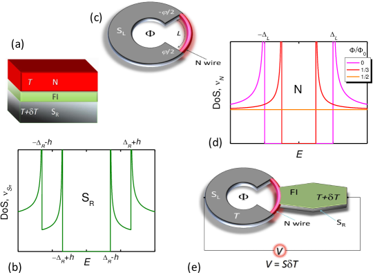
Our proposal is based on the following observation: if one tunes the DoS in N in such a way that is enhanced at those energies where the coherent peaks of the Zeeman- split superconductor occur, then should drastically increase in accordance to Eq. (2). Ideally, one would search for a material with a tunable DoS and this can be realized with our second building block: a proximity superconducting quantum interference device (SQUID), as sketched in Fig. 1(c). This consists of a superconducting loop interrupted by a normal metal wire. The contacts between N and S are assumed to be transparent thus allowing superconducting correlations to be induced in the N region. The latter manifest as opening a gap in the N metal DoS with an amplitude that can be controlled via the quantum phase difference () across the wire. Moreover, can be controlled via an externally applied magnetic flux according to , where Wb is the flux quantum. If the length () of the wire is smaller than the characteristic penetration of the superconducting correlations, its DoS can be expressed as golubov1989 ; heikkila2002supercurrent
| (3) |
where is the order parameter of the superconducting loop. Equation (3) explicitly shows that can be modulated by the magnetic flux. As displayed in Fig. 1(d), the induced gap is fully open for vanishing flux whereas it closes for . As a consequence, the N metal behaves as a phase-tunable superconductor.
Our phase-coherent thermoelectric transistor is sketched in Fig. 1(e). It combines both the proximity SQUID and the S spin-split superconductor. The S electrode is tunnel-coupled to the middle of the N wire through the FI layer. Therefore, the probability for electrons to tunnel between N and S depends on the sign of the spin. The device resembles the superconducting quantum interference proximity transistor (SQUIPT) giazotto2010squipt ; meschke2011 ; giazotto2011 ; meschke2014 ; ronzani2014 which has been well-studied in several experiments; the crucial structural difference in our device is that the thermoelectric transistor lies in the presence of the FI layer.
The efficiency of the thermoelectric transistor can be finely tuned by the applied the magnetic flux. To determine the ideal conditions for large thermoelectric efficiency we calculate the linear response transport coefficients. In other words, we calculate the charge () and heat () currents flowing through the structure when either a small voltage or a small temperature difference is applied across the junction. At steady state these currents are expressed as follows:
| (4) |
Here, is the thermoelectric coefficient defined in Eq. (2) which has now become phase dependent through . As well as the the electric () and the thermal () conductances given by the expressions: ozaeta2014
| (5a) | ||||
| (5b) | ||||
The thermoelectric efficiency of the transistor can be quantified by the usual dimensionless figure of merit defined as
| (6) |
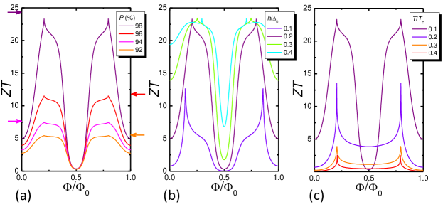
where is the thermal conductance at zero current and the Seebeck coefficient that is a measure for the thermopower [see Fig. 1(e)]. We stress that there is no theoretical limit for : if it approaches infinity the efficiency of the transistor would reach the Carnot limit. So far, only exceptionally-good thermoelectric bulk materials are able to provide values of slightly larger than 1 [see Fig. 4(a)]. By contrast, our thermoelectric transistor can result in values as large as several tens thanks to the fine tuning offered via the phase. This is displayed in Fig. 2 where the flux dependence of as a function of different parameters is shown. In Fig. 2(a) the temperature and splitting field are fixed at moderate values, and , respectively. Meservey1994 ; moodera2007phenomena ; hao1990spin ; Moodera1993 denotes the superconducting critical temperature, is the zero-temperature, zero-exchange field energy gap, and for clarity we assume that both S and S have the same value.
Therefore, by tuning the flux through the loop the theoretical zero-temperature limit assuming no inelastic scattering processes for (indicated by colored arrows corresponding to each value) ozaeta2014 can be approached without requiring ultra-low temperatures. It is also apparent that a high barrier polarization is crucial in order to achieve large values of . Good candidates for the tunneling barriers are europium chalcogenides (EuO and EuS) for which values of ranging from 80 up to almost 100% have been reported. Moodera:1988bb ; hao1990spin ; Moodera1993 ; santos2004observation ; moodera2007phenomena ; Santos:2008cm ; miao2009controlling ; li2013superconducting Also very high spin-filtering has been reported in GdN barriers Senapati:2011fm ; PalAdvanced ; pal2014pure with polarizations as large as at 15 K (even larger values are expected as decreases).
In Fig. 2(b) is set to 98%, and for different values of the induced Zeeman field is plotted showing an interesting non-monotonic behavior. cannot be externally tuned but can be partially controlled during growth of the FI/S interface since it depends on the quality of the contact. Values from 0.1 meV up to few meV for the Zeeman splitting have been reported. Tedrow1986 ; Hao1991 ; moodera2007phenomena ; li2013superconducting
We emphasize that the amplitude of the thermoelectric effect also depends on the length of the N wire. We assumed that is smaller than the superconducting coherence length [see Eq. (3)] or meaning , where is the Thouless energy and the diffusion coefficient of the N wire. Although these two energies in the existing experiments on SQUIPTs are of same order meschke2014 ; ronzani2014 , the observed modulation of the induced gap by the magnetic flux can be well described with Eq. (3) ronzani2014 . Instead of the N bridge one can use a short constriction made with the same material of the loop. In such a case one avoids the mismatch of the Fermi velocities at the interfaces, meaning the proximity effect between the bulky part of the loop and the constriction is increased.
Figure 2(c) shows the flux dependency of for different values of the temperature, at and . It is clear that the efficiency of the transistor decreases by increasing the temperature towards .
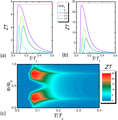
Figures 3(a) and 3(b) show the temperature dependence of for different magnetic fluxes. reaches a maximum at a finite that corresponds to the temperature for which the difference between the gap induced in N and the gap in the S electrode matches the value of the exchange field, i.e., when the coherent peaks in the DoS at the edges of the gaps [see Figs. 1(b) and 1(d)] coincide. The red dashed lines in Figs. 3(a) and 3(b) show the upper theoretical value of at zero temperature ozaeta2014 . Our device, however, allows to approach this maximum value at finite by tuning the magnetic flux. The full dependence of on both and , for and is shown by the color plot in Fig. 3(c). For and or the figure of merit can reach values close to .
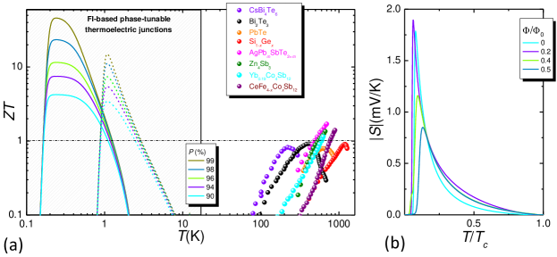
To place our device in the context of thermoelectrics we show in Fig. 4(a) the state-of-the-art bulk materials with the highest values. One of the most widely used material is Bi2Te3, tritt2006thermoelectric ; snyder2008 which at room temperature shows a close to 1. All other materials show their highest values of at high temperatures. By contrast, our transistor operates at low temperatures where it can reach values of which are larger by more than an order of magnitude. An appropriate candidate is EuO combined with superconducting Al where we expect a of for realistic values of the spin-filter efficiency. santos2004observation ; Santos:2008cm Other suitable Eu chalcogenides include EuS or EuSe. In the latter case and can be tuned by an external magnetic field. Moodera1993 An alternative to the chalcogenides is to use GdN with superconducting NbN. Senapati:2011fm ; pal2014pure Its advantage is the higher critical temperature of NbN of K. As for the normal metal bridge, it is important to achieve good electric contact with the S loop in order to develop a sizeable and tunable proximity gap. If, for instance, one uses Al as superconductor for the ring, suitable candidates for the N wire are copper (Cu) giazotto2010squipt ; meschke2011 ; meschke2014 ; ronzani2014 or silver (Ag) sns2008 .
The temperature-voltage conversion capability of the thermoelectric transistor can be quantified by the Seebeck coefficient : its temperature dependence is shown in Fig. 4(b) for selected values of the applied magnetic flux. Here we set and . The transistor is extremely sensitive at low temperatures, and provides a sharp response even to tiny temperature gradients. In particular, Seebeck coefficients as large as a few mV/K can be achieved under optimal flux tuning conditions, which have to be compared to coefficients as large as a few hundreds of V/K obtained in the abovementioned high-performance thermoelectric materials. These sizeable values of make our phase-coherent thermoelectric transistor an ideal candidate for the implementation of cryogenic power generators or ultrasensitive low-temperature general purpose thermometry as well as, for radiation sensors where heating of one of the superconductors forming the junction is achieved due to a coupling with radiation.
The work of F.G. has been partially funded by the European Research Council under the European Union’s Seventh Framework Programme (FP7/2007-2013)/ERC grant agreement No. 615187-COMANCHE, and by the Marie Curie Initial Training Action (ITN) Q-NET 264034. J.W.A.R. acknowledges funding from the Royal Society (”Superconducting Spintronics”). J.W.A.R. and F.S.B. jointly acknowledge funding from the Leverhulme Trust through an International Network Grant (grant IN-2013-033). J.S.M acknowledges funding from the National Science Foundation ((grant DMR 1207469) and the Office of Naval Research (grant N00014-13-1-0301). The work of F.S.B. has been supported by the Spanish Ministry of Economy and Competitiveness under Project No. FIS2011-28851-C02-02.
References
- (1) N. W. Ashcroft and D. N. Mermin, Solid State Physics (Saunders College, Philadelphia, 1976).
- (2) G. D. Mahan, J. Appl. Phys. 65, 1578 (1989).
- (3) P. Machon, M. Eschrig, and W. Belzig, Phys. Rev. Lett. 110, 047002 (2013).
- (4) A. Ozaeta, P. Virtanen, F. Bergeret, and T. T. Heikkilä, Phys. Rev. Lett. 112, 057001 (2014).
- (5) P. Machon, M. Eschrig, and W. Belzig, arXiv: 1402.7373 (2014).
- (6) A. Golubov and M. Y. Kupriyanov, Zh. Eksp. Teor. Fiz 96, 1420 (1989).
- (7) T. T. Heikkilä, J. Särkkä, and F. K. Wilhelm, Phys. Rev. B 66, 184513 (2002).
- (8) F. Giazotto, J. T. Peltonen, M. Meschke, and J. P. Pekola, Nat. Phys. 6, 254 (2010).
- (9) M. Meschke, J. T. Peltonen, J. P. Pekola, and F. Giazotto, Phys. Rev. B 84, 214514 (2011).
- (10) F. Giazotto and F. Taddei, Phys. Rev. B 84, 214502 (2011).
- (11) R. N. Jabdaraghi, M. Meschke, and J. Pekola, Appl. Phys. Lett. 104, 082601 (2014).
- (12) A. Ronzani, C. Altimiras, and F. Giazotto, arXiv:1404.4206.
- (13) J. Moodera, X. Hao, G. Gibson, and R. Meservey, Phys. Rev. Lett. 61, 637 (1988).
- (14) X. Hao, J. Moodera, and R. Meservey, Phys. Rev. B 42, 8235 (1990).
- (15) T. S. Santos and J. S. Moodera, Phys. Rev. B 69, 241203 (2004).
- (16) J. S. Moodera, T. S. Santos, and T. Nagahama, Jour. of Phys.: Cond. Matt. 19, 165202 (2007).
- (17) R. Meservey and P. M. Tedrow, Phys. Rep. 238, 173 (1994).
- (18) J. S. Moodera, R. Meservey, and X. Hao, Phys. Rev. Lett. 70, 853 (1993).
- (19) T. S.Santos, J. S. Moodera, K. V. Raman, E. Negusse, J. Holroyd, J. Dvorak, M. Liberati, Y. U. Idzerda, and E. Arenholz, Phys. Rev. Lett. 101, 147201 (2008).
- (20) G.-X. Miao and J. S. Moodera, App. Phys. Lett. 94, 182504 (2009).
- (21) B. Li, N. Roschewsky, B. A. Assaf, M. Eich, M. Epstein-Martin, D. Heiman, M. M nzenberg, and J. S. Moodera. , Phys. Rev. Lett. 110, 097001 (2013).
- (22) K. Senapati, M. G. Blamire, and Z. H. Barber, Nat. Mat. 10, 1 (2011).
- (23) A. Pal, Z. Barber, J. Robinson, and M. Blamire, Adv. Mat. 25, 5581 (2013).
- (24) A. Pal, K. Senapati, Z. Barber, and M. Blamire, Nat. Comm. 5 (2014).
- (25) P. M. Tedrow, J. E. Tkaczyk, and A. Kumar, Phys. Rev. Lett. 29, 1651 (1986).
- (26) X. Hao, J.S. Moodera, and R. Meservey, Phys. Rev. Lett. 67, 1342 (1991).
- (27) T. M. Tritt and M. Subramanian, MRS Bulletin 31, 188 (2006).
- (28) G. J. Snyder and E. S. Toberer, Nat. Mat. 7, 105 (2008).
- (29) H. Le Sueur, P. Joyez, H. Pothier, C. Urbina, and D. Esteve, Phys. Rev. Lett. 100, 197002 (2008).