Dynamic phase diagram of dc-pumped magnon condensates
Abstract
We study the effects of nonlinear dynamics and damping by phonons on a system of interacting electronically pumped magnons in a ferromagnet. The nonlinear effects are crucial for constructing the dynamic phase diagram, which describes how “swasing” and Bose-Einstein condensation emerge out of the quasiequilibrated thermal cloud of magnons. We analyze the system in the presence of magnon damping and interactions, demonstrating the continuous onset of stable condensates as well as hysteretic transitions.
I Introduction
Elementary excitations of uniform ferromagnets (magnons) are bosonic in nature, thus exhibiting properties similar in character to those of cold atoms, photons, and excitons. Each of these systems can undergo a bosonic condensation wherein the lowest-energy mode displays a macroscopic occupation. The condensate, thereafter, manifests a macroscopic phase, spontaneously breaking U(1) gauge symmetry. Magnons have been expected Kalafati and Safonov (1989); *kalafatiJETP91 and observed Demokritov et al. (2006) to undergo condensation under microwave pumping. Their condensate phase has a transparent physical interpretation as the precessional angle of collective magnetic dynamics.
In Ref. Bender et al., 2012, magnon condensates are proposed to be realized through dc electronic pumping. To this end, a ferromagnetic insulator, e.g., yttrium iron garnet (YIG), is directly attached to a conducting normal metal. Spin-pumping by the precessing magnet (or spin waves), governed by a sizable spin-mixing conductance across the interface, results in a loss of magnons and the corresponding creation of particle-hole excitations in the normal metal. This magnetic bleeding may be overcome either by increasing the current in the normal metal, which transports angular momentum into the ferromagnet by the spin Hall effect,Ando et al. (2008); *liuPRL11sh or by utilizing a temperature gradient across the interface, thus actuating the spin Seebeck effect.Uchida et al. (2008); *uchidaNATM10 Under a critical spin Hall and/or Seebeck biases, an excess of incoherently pumped magnons can precipitate a spontaneous condensation.
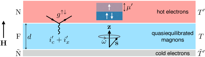
In this paper, we build upon the proposal in Ref. Bender et al., 2012 by making two important advancements. First, we include nonlinear effects associated with magnon-magnon interactions in the presence of finite-angle collective precession. Nonlinear effects can play an important role in stabilizing coherent dynamics under large spin Hall/Seebeck biases, as well as accounting for the interaction of the condensate with the thermal magnon cloud. Second, we include Gilbert damping due to magnon-lattice coupling and allow for an additional energy-sink channel by attaching a poor spin-sink normal metal on the other side of the ferromagnet. See Fig. 1 for a schematic of our setup. The role of this second normal metal in our model is to (i) anchor the adjacent lattice temperature and (ii) provide a reservoir that dissipates excess energy injected along with magnons from the first normal metal, which helps in fomenting condensation.
The paper is organized as follows. In Sec. II, we start by constructing the nonlinear dynamics of the condensate (A) and incoherent dynamics of the cloud (B), including its interaction with the condensate. In Sec. III, we derive rate equations for spin and energy transfer into the normal metal N and the phonon bath. In Sec. IV, the dynamic phase diagram of the pumped magnetic system is constructed, focusing on two special limits: (A) the fixed magnon temperature regime, which is controlled by spin flows between different subsystems (of magnons, electrons, and phonons), (B) the floating magnon temperature regime, in which the steady state is determined by self-consistent flows of both spin and energy. In both cases, we find regions of stable condensate with second-order as well as first-order hysteretic transitions out of the normal phase. Finally, Sec. V summarizes our findings and offers an outlook.
II Magnetic dynamics
II.1 Condensate dynamics
We start by considering dynamics at absolute zero temperature, assuming only the lowest mode is excited. For simplicity, we neglect magnetostatic effects, such that the lowest-frequency excitation is given by homogeneous (monodomain) magnetic precession. Supposing, furthermore, cylindrical symmetry about the axis, the effective monodomain Hamiltonian can be phenomenologically expanded as
| (1) |
where is the total (macro)spin of the ferromagnet (in units of ), is its -axis projection, is the applied field in the direction (upon absorbing the gyromagnetic ratio), and is the axial anisotropy (with corresponding to an easy plane). We suppose that , such that spin is oriented in the direction in the ground state.
The spin algebra, , can be conveniently recast in terms of the Holstein-Primakoff bosons:Holstein and Primakoff (1940)
| (2) |
where , is the total spin, and is a time-dependent ground-state magnon operator satisfying commutation relation . The Hamiltonian in Eq. (1) is thus rewritten in terms of free-boson and interacting contributions (dropping a constant offset):
| (3) |
A classical precession for large spin corresponds to a coherent state for boson : , such that , where is the ground state with . The quantum-to-classical correspondence is provided by , where the phase of corresponds to the azimuthal angle of spin in the plane: . For small-angle precession, :
| (4) |
where .
In the Heisenberg picture,
| (5) |
where , when acting on the magnon-number, , eigenstate , and stands for the anticommutator. (This corresponds to the energy for adding a magnon to the state .) In the classical limit, , this gives the familiar Larmor precession frequency:
| (6) |
Indeed, the variables and are canonically conjugate: , . Viewing this as a special (cylindrically-symmetric) instance of the Landau-Lifshitz equation,Lifshitz and Pitaevskii (1980) we can easily extend the Hamiltonian (1) to include more general magnetic interactions. A common phenomenology for dissipation, furthermore, is provided by the Gilbert damping,Gilbert (2004) which endows frequency (6) with an imaginary component, , where is a material-dependent constant. The corresponding magnon-number relaxation rate, , is proportional to the precession frequency.
II.2 Thermal cloud
At a finite temperature , the thermally-excited magnons also contribute to the total spin angular momentum. For large bulk samples of volume , it is now natural to switch from the total spin to the spin density . Extending Eq. (4) to this case, while assuming that , the Curie temperature (such that we limit our attention to small-angle magnetic dynamics), this spin density can be written [relative to the saturated value at , where ]:
| (7) |
Here, , in terms of the condensate magnon density (i.e., density of magnons occupying the lowest mode) and the thermal cloud density (which is composed of the magnon states excited above the lowest-energy mode); plays the role of the condensate order parameter, with being the -plane azimuthal angle of the coherent spin precession. Note that only the magnon condensate component contributes to the spin-density projections.
The intrinsic dynamics of magnons with wavenumber , by extension of Eq. (6), is given by
| (8) |
where is the ferromagnetic exchange stiffness (in appropriate units) and is the (monodomain) ferromagnetic-resonance frequency. Here, for simplicity, we are retaining only the nonlinear term stemming from the anisotropy term in the Hamiltonian,Note (1) which would arise from, e.g., the global shape anisotropy.Suhl (1957) This is justified so long as the key nonlinearity stems from the feedback of the condensate on the frequency of the magnon modes.Note (2) Gilbert damping still gives for the -dependent relaxation rate.
III Transport Rate Equations
The rate equation for the magnon-number density, , is governed by the Landau-Lifshitz-Gilbert (LLG) dynamics of the condensed and thermal magnons, including their interactions, damping of spin and energy to the lattice, and spin and energy transport between the ferromagnet and the normal-metal reservoirs that are governed by the electron-magnon scattering. The zero-temperature condensate dynamics are described by the classical LLG equation of motion (extended to include spin-transfer torques) for the unit-vector collective spin direction :
| (9) |
where is the effective field, is the vectorial spin accumulation in N,
| (10) |
in terms of the complex-valued spin-mixing conductance (in units of , and per unit area) of the FN interface and the F layer thickness . The left-hand side of Eq. (9) is the standard LLG equation,Lifshitz and Pitaevskii (1980); *gilbertIEEEM04 while the right-hand side consists of the static spin-transfer torquesSlonczewski (1996); Berger (1996) and spin-pumping torquesTserkovnyak et al. (2002); *tserkovRMP05 (which are Onsager reciprocalTserkovnyak and Mecklenburg (2008)).
Rewriting Eq. (9) in spherical coordinates, in terms of the condensate density ,
| (11) |
where , we have
| (12) | ||||
Here, is given by Eq. (8), with . These equations generalize the Hamilton’s equations of motion for the canonically-conjugate pair of variables to include dissipation (magnon-lattice coupling) and spin-transfer torques/spin-pumping (magnon-electron coupling). Assuming that , which is nearly always the case in practice, Eqs. (12) give for the condensate rate equation
| (13) |
where
| (14) |
captures the effects of Gilbert damping and spin-transfer torque. [Here, we combined the expressions for and in Eq. (12) and dropped the terms that are quadratic in and .] Since is eliminated by this substitution, hereafter stands for only.
According to Eq. (14), the condensate rate of change (13) is scaled by the geometrical factor , which can be divided out and, if , disregarded. When in the following we complement the magnon rate equation with thermal contributions, this factor could be absorbed by an appropriate rescaling of the thermal terms, which would lead to small cross terms between the quantities associated with the condensate and the thermal cloud. The Gilbert-damping and spin-transfer contributions to the zero-temperature condensate rate equation are then respectively given by
| (15) | ||||
| (16) |
Equation (16) was derived in Ref. Bender et al., 2012 in a perturbative treatment of the electron-magnon scattering, which is consistent with neglecting terms that are quadratic in ’s.
At finite temperatures,
| (17) |
where is the rate of spin transfer from the thermal cloud to condensate. The thermally-excited magnons also obey generalized LLG/spin-torque relations, which we derive below. In order to simplify the following discussion, we will limit our attention to the situations when spin-preserving magnon-magnon interactions are fast enough that magnons form a Bose-Einstein distribution with an effective temperature and chemical potential . The total thermal-cloud density is then given by
| (18) |
where is the magnon chemical potential relative to the band edge (set at ), which, on the absolute scale, is shifted by the condensate frequency ; is the magnon density of states; and . Writing the thermal-cloud rate equation, , in terms of the Gilbert-damping, , and spin-torque, , contributions, we assert for the former:
| (19) |
where is the inverse (effective) temperature of phonons (which are assumed to be responsible for the Gilbert damping) and . The spin-torque rate is given byBender et al. (2012)
| (20) | ||||
where is the inverse normal-metal N electron temperature.Note The rate equation for the thermal-cloud is given by
| (21) |
where is the rate of spin transfer from the condensate to cloud.
The total spin current passing through the normal-metal interface is found by adding Eqs. (17) and (21):
| (22) |
where we set , assuming magnon-number preserving magnon-magnon interactions (which is rooted in spin conservation for a cylindrically-symmetric magnetic system). The expression for the net spin current , using rate equations for the condensate, Eqs. (15) and (16), and thermal cloud, Eqs. (19) and (20), forms one of our key results. In order to find steady states, we will have to solve for . Subject to external conditions of pumping, two unknowns thus need to be established: the effective temperature, , and chemical potential, , of magnons.
In order to evaluate a common temperature and chemical potential for the magnons, we also need to consider the energy flow into the system. The total magnon energy density in our model is given by , where
| (23) |
is the condensate energy and
| (24) |
is the thermal-cloud energy. We recall, in particular, that in the above equations is affected by the presence of the condensate . The total energy-transfer rate from N and the lattice into magnons is thus given by:
| (25) |
where and are given by the expressions similar to Eqs. (19) and (20) but with an additional factor of in the integrands.Note (3)
IV Dynamic phase diagrams
IV.1 Fixed magnon temperature
If we suppose that the magnetic coupling to the phonons is sufficiently strong that the magnon temperature is fixed by the phonon reservoir, , we may disregard the energy current . In this limit, the spin current fully determines the state of the system. The magnon temperature in a magnetic film sandwiched by two metals, as sketched in Fig. 1, can similarly be fixed by the electron temperatures and [for example, in a mirror-symmetric structure], either through direct magnon-electron scattering at the interfaces or via magnon-phonon interaction. Under the reigning assumption that the magnonic cloud and condensate maintain internal thermodynamic equilibrium at all times, the magnet is always either in normal phase (NP) or condensate phase (CP). Then, only one variable is left free to vary: in NP or in CP, which is controlled by the spin current flowing into the magnetic subsystem.
In a normal phase, the condensate is absent (), and the magnon current goes entirely into the thermal cloud:
| (26) |
where consists only of the normal component, Eqs. (19), (20), which depend on . We will be treating the dependence inside NP numerically.
If the magnons are condensed (i.e., ) while their temperature is fixed, the spin current, Eq. (22), must, via magnon-magnon interactions, be entirely transformed into the condensate density:
| (27) |
Even in this simple limit, however, we cannot obtain an exact analytic solution for , since the flux has an implicit nonlinear dependence on [through the dependence of on ]. When , which is the limit we are focusing on throughout, we can expand in its powers:
| (28) |
Here, , after setting and in Eqs. (19) and (20). According to Eqs. (15) and (16),
| (29) |
and
| (30) |
where and are thermal-magnon corrections. Using Eqs. (19) and (20), the latter are evaluated at to be:
| (31) |
and
| (32) |
up to numerical factors of order unity. Here, is the Curie temperature. These corrections are clearly unimportant, so long as (recalling that throughout), and will be omitted in the following. We thus conclude, in particular, that .
IV.1.1 Swasing
We start by considering the low-temperature limit of a stiff ferromagnet, where the thermal-current contribution in Eq. (28) can be disregarded. The condensate dynamics, , is then governed by two transport coefficients: and .
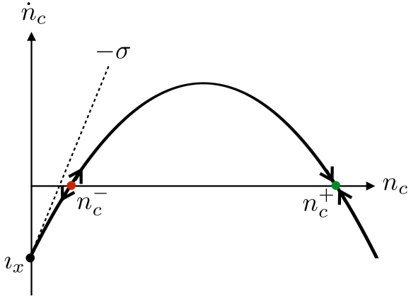
The coefficient in Eq. (28) represents an effective damping of the condensate and describes a competition between, on the one hand, damping by phonons and electrons (captured by the first term in , proportional to , where parametrizes Gilbert damping and spin pumpingTserkovnyak et al. (2002)) and, on the other, spin-transfer torque from the normal-metal N (captured by second term in , proportional to spin accumulation ). When the former contribution is larger, is positive, and the torque provided by the second term Eq. (28) relaxes the condensate spin density (with the total spin decaying towards the axis). Conversely, upon the application of a sufficiently large and positive spin accumulation , is negative, and the net torque from the linear in term in Eq. (28) drives the condensate spin towards the axis. The quadratic term proportional to in Eq. (28) describes a nonlinear enhancement of damping, which ultimately curbs the exponential growth of the condensate when , leading to the fixed point
| (33) |
In the absence of intrinsic Gilbert damping, i.e., , the effective damping is proportional to . This was first pointed out by Berger,Berger (1996) who coined the term swaser (spin-wave amplification by stimulated emission of radiation) to describe the coherent emission of spin waves, signified by negative damping, when the pumping overcomes the intrinsic threshold associated with the gap . This swasing instability may be understood thermodynamically: Because the condensate carries no entropy, the free-energy change due the creation of magnons and the corresponding annihilation of the up-electron/down-hole pairs is
| (34) |
When , the condensate is damped by the transfer of angular momentum and energy out of the magnet into N; when , however, the absorption of energy by the condensate becomes entropically beneficial, signaling an instability.
A finite in Eq. (29) raises the swasing instability threshold to
| (35) |
in analogy to the lasing threshold in a lossy optical cavity. In particular, when Gilbert damping dominates over spin pumping (which is the case in sufficiently thick magnetic films), i.e., , we obtain , which reproduces the classical Slonczewski’s spin-transfer torque instability.Slonczewski (1996)
IV.1.2 Bose-Einstein condensation
We now focus on the finite-temperature steady-state behavior (fixed points), determined by the condition . Namely, for a given set of parameters (, , , …), we look for possible solutions for both NP (defined by the existence of a real value of for which ) and CP (defined by the existence of a real, positive value of for which ). While the NP solutions are found numerically, the analytic expansion in Eq. (28) allows for a general CP solution to :
| (36) |
which is depicted in Fig. 2.
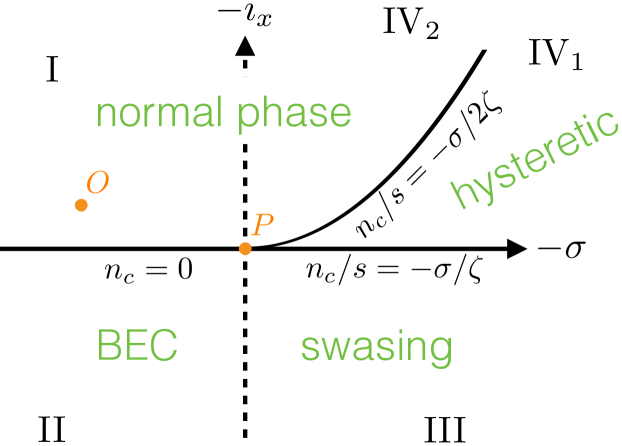
The resultant phase diagram may be divided into four regions, I-IV, according to the signs of the coefficients and : and (region I), and (region II), and (region III), and and (region IV). In parameter space, regions I and III each share phase boundaries with regions II and IV. All four regions meet when and , which appears as a single critical point in the phase diagram. We now discuss in some detail the physical behavior in each of the four regions, with the help of Fig. 3 as visual guidance.
In region I, neither solution is real and positive, dictating that the magnons must settle in NP at some for which , as we find numerically. In region II, represents a real-valued, stable solution to the condensate equation of motion. While the condensate is damped through the second and third terms in Eq. (28), it is replenished by the thermal cloud, , which can be driven by thermal gradient . The magnet reaches a steady state, wherein angular momentum is pumped into the thermal cloud and transferred to the condensate by magnon-magnon interactions, which in turn decays by the combination of Gilbert damping and spin pumping. Numerically, we find no NP solution coexisting with CP in region II. Note that here is finite even in the absence of the nonlinearity .
The boundary between regions I and II is defined by the condition , corresponding to . It thus follows that is continuous at the associated NP/CP phase transition, given by in region I and in the incipient region II. Conversely, in region II and decreases continuously, , in region I. We identify this dynamic second-order phase transition as a Bose-Einstein condensation, whose order parameter is given by , where . In contrast to swasing, where , the condensate decay is compensated here by the thermal magnon injection, , that replenishes it.
IV.1.3 Full phase diagram
Similarly to region II, region III produces a positive, stable solution to the condensate equation of motion. In contrast to region II, however, diverges as , demonstrating the importance of the nonlinearity in stemming the condensate growth. In this region, swasing is supplemented with thermal spin transfer , which increases . Because no solution to exists for (in our numerical calculation), we conclude that only CP is present in region III.
Region IV may itself be divided further into two subregions: IV1 and IV2 defined respectively by . In subregion IV1, both and are real, but only the former solution is stable (see Fig. 2). Depending on whether at , the magnetic system flows towards CP fixed point at or NP, respectively, at , indicating CP/NP hysteresis. In contrast, both and are complex in subregion IV2, precluding CP. In all of region IV, therefore, an NP solution to exists, which evolves continuously within this region. The CP solution existing in subregion IV1, on the other hand, evolves continuously into a CP swasing phase in region III. Region IV is opposite to II both in the reversal of the sign of (such that the condensate tends to swase) and (such that the thermal magnons are pumped out of the magnet, thus suppressing the condensate). The balancing act between negative and , as depicted in Fig. 2, allows for a stable condensate in subregion IV2.
We summarize the above discussion in Fig. 3: The boundary between regions I and II describes a continuous phase transition between an NP and the Bose-Einstein condensate (BEC). The boundary between I and IV2 is a crossover within the NP, while the boundary between II and III is a crossover between swasing and BEC (both instances of a CP). Boundaries delineating the hysteretic region IV1 define history-dependent first-order transitions: An NP in IV1 jumps to a finite condensate density when entering III, and a CP phase in IV1 jumps from a finite condensate density to a normal state with a finite when entering IV2. All the phase-transition lines and crossovers emanate from the critical point .
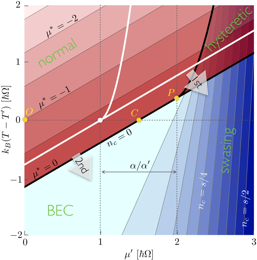
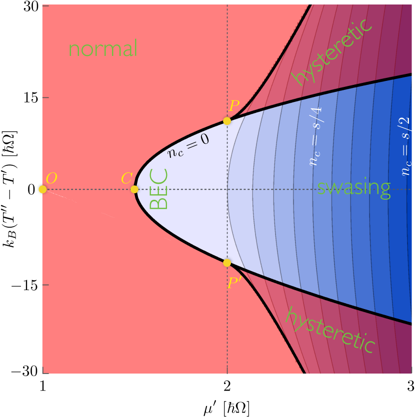
When drawing the physical phase diagram in terms of the experimentally-controlled parameters (which, in turn, determine and ), the essential structure of Fig. 3 is preserved, albeit somewhat distorted, as shown in Fig. 4. While corresponds linearly to , according to Eq. (29), is generally a nonlinear function of and . Since, for a fixed , increases with increasing temperature , however, we can think of as parametrizing (keeping fixed). This explains why the structure of the physical phase diagram in Fig. 4 is anticipated by Fig. 3.
Let us now parametrize in detail the phase-transition lines depicted in Fig. 4. We denote by the phase boundary corresponding to the abscissa in Fig. 3 (i.e., the curve delineating phases II and III) and by the boundary between regions IV1 and IV2 [strictly above the swasing instability (35), i.e., ], which emanates out of the critical point . When (i.e., the ambient temperature sets the largest relevant energy scale), the current may be linearized in , , and , allowing us to analytically derive the expressions for and . In this regime, the former is linear in and given by:
| (37) |
where is the Riemann zeta function. Below the swasing threshold, condensate forms when exceeds . In the absence of a temperature bias, , Eq. (37) indicates the formation of a condensate when exceeds (denoted in Fig. 4 by ).Note
The curve , in turn, is defined by:
| (38) |
where is the gamma function. The curves and , according to Eqs. (37) and (38) are shown in Fig. 4 as solid black lines for and solid white lines . The dependence of the transition lines on a gradual change in the strength of damping and nonlinearity is shown in Fig. 5.

IV.2 Floating magnon temperature
In addition to angular momentum, energy transfer from the ferromagnet into the adjacent normal metals and its crystal lattice, in general, also needs to be balanced. In the previous section, we made a simplifying assumption that the magnon temperature was pinned by phonons and/or electrons, which provided a very efficient energy sink. Here we relax that assumption, which necessitates keeping track of the total magnon energy on par with the magnon number. We still, however, suppose that magnon-magnon interactions are sufficiently strong that the magnons remain internally thermalized to a Bose-Einstein distribution with a well-defined effective temperature and chemical potential (relative to the magnon-band bottom) at all times. We also retain the assumption that cloud and condensate always remain in mutual equilibrium, namely, that vanishes for (NP) and requires that (CP). In analogy with the condensate and normal-phase spin currents discussed above, we define the condensate and normal-phase energy currents and , respectively, according to Eq. (25), which simplifies the stability analysis of the CP.
At any time, there now exist two dynamical variables. In NP, these are and , governed by the implicit, coupled rate equations and ; in CP, and , governed by Eqs. (22) and (25). In contrast to the expansion of the magnon current in , Eq. (28), a simple general analytic expansion of the currents in in either phase is not possible, and we must resort to a numerical treatment.
In general, the steady-state temperature and the chemical potential (or condensate spin density ) in each phase are determined from the stable fixed points of the respective pair of coupled rate equations. The resultant numerical phase diagram is shown in Fig. 6. The energy accompanying angular-momentum transfer into the ferromagnet creates additional heating (cooling) when (phonon temperature), which hinders (facilitates) condensation relative to the fixed-temperature regime. In particular, condensation via temperature gradient alone (i.e., ) no longer occurs. Below the swasing instability (i.e., ), each steady-state solution in NP coincides with a solution in CP, indicating the second-order phase transition. Above the threshold for swasing, on the other hand, hysteretic regions appear, where, depending on the initial conditions, the solutions flow toward stable fixed points in NP or CP. These features are qualitatively similar to those discussed in the case of a fixed magnon temperature, Sec. IV.1.
In the case of a low temperature gradient (), the incipient condensation may be understood by expanding and in , , and (all of which are assumed to be much smaller than the ambient temperature) and solving the steady-state equations to obtain analytic solutions for and . When (denoted by in Fig. 6), no condensate solution exists; increasing beyond this critical point, the condensate density continuously increases from zero. (Note that the same bias at describes the onset of condensation under zero temperature bias both in the fixed- and floating-temperature regimes.) As in the fixed-temperature case, furthermore, when , unstable analytic solutions for appear, suggesting the presence of hysteresis when the temperature gradient is restored; correspondingly, (two) critical points and manifest under a sufficient temperature bias at the swasing instability (35).
The above linearized treatment for the currents and , however, fails to capture the detailed phase behavior when . There, the spin and energy fluxes that are quadratic in thermal bias are essential for generating the full structure of the phase boundaries depicted in Fig. 6. In particular, we see that the condensate is suppressed under large temperature biases of both signs: When , the magnons injected by the normal metal are relatively cold but there are ultimately too few of them to precipitate a condensate; when , on the other hand, the magnon injection rate is high but they are too hot to condense. Only at intermediate thermal biases do we reach a compromise between the magnon injection rate and the energy they carry, which allows for a stable condensate to form.
V Summary and Outlook
We studied the steady-state behavior of an insulating magnet driven by the combination of a thermal gradient and spin-transfer torque across its interface with an adjacent normal metal. Agitated by the interfacial magnon-electron and bulk magnon-lattice interactions, our theory describes the emergent nonlinear coherent motion of the condensate (in a quasiequilibrium with the thermal cloud of magnons), demonstrating a surprisingly rich dynamic phase diagram.
The stability analysis of the driven coherent motion depends crucially on the form of the magnetic anisotropy. Our detailed analysis was specific to an easy-plane magnetic film subjected to a large out-of-plane magnetic field (such that the magnetic ground state is nondegenerate). In the case of other geometries and magnetic anisotropies, the phase diagram can be altered. Furthermore, in other configurations, where spin-rotational symmetry is broken in all directions, three-magnon scattering processes would violate magnon conservation, which is built into our model. We nevertheless expect that the essential nature of the first- and second-order instabilities predicted in our model to be generic, although the details would depend on the specific experimental realization. We emphasize that one of the key features predicted by our theory is a possibility of a continuous formation of the condensate in the presence of a temperature gradient alone, which may be less sensitive to the particular magnetic orientation than the more familiar instabilities invoked by a spin-transfer torque.
The presence of coherently-precessing magnetic phases may manifest experimentally in a variety of ways. Collective magnetic modes driven by dc currents may be detected either by their microwave signatures or differential dc response (both in the charge and thermal sectors) in the steady state, similarly to the conventional spin-transfer torque instabilities.Kiselev et al. (2003) The thermal properties of the magnon condensates, in particular, may differ dramatically from the normal phase, if, for example, the lateral propagation of heat in the plane of our heterostructure can be carried collectively by magnetic dynamics. In addition, unlike thermal magnons that generally travel diffusively with a microscopic spin-diffusion length, low-frequency condensates can carry spin signals over macroscopic distances.Sonin (2010); *takeiCM13 Such collective and nonlocal transport signatures of condensation warrant further studies, both theoretically and experimentally.
Acknowledgements.
This work was supported in part by FAME (an SRC STARnet center sponsored by MARCO and DARPA), the NSF under Grant No. DMR-0840965, and by the Kavli Institute for Theoretical Physics through NSF Grant No. PHY11-25915.References
- Kalafati and Safonov (1989) Y. D. Kalafati and V. L. Safonov, JETP Lett. 50, 149 (1989).
- Kalafati and Safonov (1991) Y. D. Kalafati and V. L. Safonov, Sov. Phys. JETP 73, 836 (1991).
- Demokritov et al. (2006) S. O. Demokritov, V. E. Demidov, O. Dzyapko, G. A. Melkov, A. A. Serga, B. Hillebrands, and A. N. Slavin, Nature 443, 430 (2006).
- Bender et al. (2012) S. A. Bender, R. A. Duine, and Y. Tserkovnyak, Phys. Rev. Lett. 108, 246601 (2012).
- Ando et al. (2008) K. Ando, S. Takahashi, K. Harii, K. Sasage, J. Ieda, S. Maekawa, and E. Saitoh, Phys. Rev. Lett. 101, 036601 (2008).
- Liu et al. (2011) L. Liu, T. Moriyama, D. C. Ralph, and R. A. Buhrman, Phys. Rev. Lett. 106, 036601 (2011).
- Uchida et al. (2008) K. Uchida, S. Takahashi, K. Harii, J. Ieda, W. Koshibae, K. Ando, S. Maekawa, and E. Saitoh, Nature 455, 778 (2008).
- Uchida et al. (2010) K. Uchida, J. Xiao, H. Adachi, J. Ohe, S. Takahashi, J. Ieda, T. Ota, Y. Kajiwara, H. Umezawa, H. Kawai, G. E. W. Bauer, S. Maekawa, and E. Saitoh, Nature Mater. 9, 894 (2010).
- Holstein and Primakoff (1940) T. Holstein and H. Primakoff, Phys. Rev. 58, 1098 (1940).
- Lifshitz and Pitaevskii (1980) E. M. Lifshitz and L. P. Pitaevskii, Statistical Physics, Part 2, 3rd ed., Course of Theoretical Physics, Vol. 9 (Pergamon, Oxford, 1980).
- Gilbert (2004) T. L. Gilbert, IEEE Trans. Magn. 40, 3443 (2004).
- Note (1) If, instead, the dominant nonlinearity would step from a local crystalline anisotropy , rather than the global shape anisotropy , there would be a factor of 2 in front of in Eq. (8\@@italiccorr).
- Suhl (1957) H. Suhl, J. Phys. Chem. Solids 1, 209 (1957).
- Note (2) We are neglecting, in particular, self-energy corrections due to interactions within the thermal cloud, as well as the condensate frequency shift due to the cloud, which should not be important at , where .
- Slonczewski (1996) J. C. Slonczewski, J. Magn. Magn. Mater. 159, L1 (1996).
- Berger (1996) L. Berger, Phys. Rev. B 54, 9353 (1996).
- Tserkovnyak et al. (2002) Y. Tserkovnyak, A. Brataas, and G. E. W. Bauer, Phys. Rev. Lett. 88, 117601 (2002).
- Tserkovnyak et al. (2005) Y. Tserkovnyak, A. Brataas, G. E. W. Bauer, and B. I. Halperin, Rev. Mod. Phys. 77, 1375 (2005).
- Tserkovnyak and Mecklenburg (2008) Y. Tserkovnyak and M. Mecklenburg, Phys. Rev. B 77, 134407 (2008).
- (20) The additional factor of on the right-hand side of Eq. (20) relative to Eq. (16) stems from the fact that the FN interface, where the torques develop, coincides with the antinode of the thermal-magnon normal modes.Hoffman et al. (2013); *kapelrudPRL13 As a consequence, point in Fig. 4, which corresponds to , precedes the swasing threshold [at ] along the axis.
- Hoffman et al. (2013) S. Hoffman, K. Sato, and Y. Tserkovnyak, Phys. Rev. B 88, 064408 (2013).
- Kapelrud and Brataas (2013) A. Kapelrud and A. Brataas, Phys. Rev. Lett. 111, 097602 (2013).
- Note (3) The term in Eq. (25\@@italiccorr) can be dropped in the spirit of our approximations (having supposed that the thermal cloud has a negligible feedback on the condensate frequency, i.e., ).
- Kiselev et al. (2003) S. I. Kiselev, J. C. Sankey, I. N. Krivorotov, N. C. Emley, R. J. Schoelkopf, R. A. Buhrman, and D. C. Ralph, Nature 425, 380 (2003).
- Sonin (2010) E. B. Sonin, Adv. Phys. 59, 181 (2010).
- (26) S. Takei and Y. Tserkovnyak, arXiv:1311.0288.