Ultralong-range Rydberg molecules in combined electric and magnetic fields
Abstract
We investigate the impact of combined electric and magnetic fields on the structure of ultralong-range polar Rydberg molecules. Our focus is hereby on the parallel as well as the crossed field configuration taking into account both the -wave and -wave interactions of the Rydberg electron and the neutral ground state atom. We show the strong impact of the -wave interaction on the ultralong-range molecular states for a pure -field configuration. In the presence of external fields the angular degrees of freedom acquires vibrational character and we encounter two- and three-dimensional oscillatory adiabatic potential energy surfaces for the parallel and crossed field configuration, respectively. The equilibrium configurations of local potential wells can be controlled via the external field parameters for both field configurations depending of the specific degree of electronic excitation. This allows to tune the molecular alignment and orientation. The resulting electric dipole moment is in the order of several kDebye and the rovibrational level spacings are in the range of MHz. Both properties are analyzed with of varying field strengths.
I Introduction
The preparation and control of ultracold atomic and molecular systems offer a unique platform for a detailed understanding and analysis of fundamental quantum processes. The external degrees of freedom can be accessed by designing and switching almost arbitrarily shaped traps Grimm00 ; Folman02 ; Pethick08 which are created by external electric, magnetic or electromagnetic fields. Furthermore, interatomic interaction strength can be tuned via magnetic or optical Feshbach resonances Koehler06 ; Bloch08 ; Chin10 ; Jochim03 ; Knoop09 ; Repp13 . A prominent new species are the weakly bound ultralong-range diatomic molecules composed of a ground state and a Rydberg atom. Theoretically predicted more than a decade ago Greene00 they have been recently discovered experimentally Bendkowsky09 . The molecular Born-Oppenheimer potential energy surfaces, which are responsible for the diatomic binding, show for these species an unusual strong oscillatory behavior providing a large number of local potential minima. This structure can be understood intuitively as the interaction of a neutral ground state atom with the Rydberg atom which can be modeled as a low energy scattering potential between the quasi free Rydberg electron and the ground state atom. In a first approximation, this so called -wave Fermi pseudopotential ansatz Fermi34 ; omont77 leads to diatomic molecular species with unique features like internuclear distances in the order of the Rydberg atom. For the considered quantum numbers - the vibrational binding energies are in the MHz and GHz regime depending on the type of states. More specifically, low-angular momentum non-polar states and large angular momentum polar states, so-called trilobites, have been predicted Greene00 . They possess electric dipole moments in the range of 1 Debye (low-) up to 1 kDebye (high-) in the polar case. The large electric dipole moment of the latter make them accessible for external field manipulation which opens the possibility for the control of the molecular degrees of freedom. For instance, the selective excitation of stationary molecular -states in external magnetic fields was demonstrated recently possessing an extraordinary degree of alignment or antialignment with respect to the magnetic field axis Krupp14 . The impact of either magnetic or electric fields on ultralong-range molecules has been studied in previous works Lesanovsky07 ; Kurz13 . It has been shown that in the presence of an external field the angular degree of freedom between the field and the internuclear axis acquires vibrational character resulting in two-dimensional adiabatic potential energy surfaces (PES). A pure magnetic field yields in molecular states oriented perpendicular to the molecular axis and leads, with increasing field strength, to a monotonic lowering of the magnitude of the electric dipole moment Lesanovsky07 . However, a pure electric field forces the molecule into a parallel oriented configuration with an electric dipole of growing magnitude for increasing electric field strength Kurz13 . Combining electric and magnetic fields in a crossed field configuration the existence and properties of so-called giant dipole ultralong-range molecules had been analyzed Kurz12 which corresponds to the situation of a magnetic field dominating over the Coulomb interaction.
In the present work we explore the impact of combined electric and magnetic fields, more specifically the cases of parallel and crossed (perpendicular) fields, on the structure and dynamics of high- ultralong-range diatomic rubidium molecules. Our analysis goes beyond the -wave approximation taking into account the next order -wave term in the Fermi-pseudopotential. Already for the case of a magnetic field only we demonstrate the strong impact of the -wave contribution. Due to -wave interactions the potential wells providing the weakly bound trilobite states vanish beyond a critical magnetic field strength and consequently no bound states exist anymore. For combined electric and magnetic fields the topology of the PES strongly depend on the specific field configuration and the applied field strengths. The resulting PES show a strong oscillatory behavior with depths up to hundreds of MHz and we find rovibrational bound states with level spacings in the MHz regime. By tuning the field parameters separately we can control the molecular orientation for the parallel configuration from a perpendicular to an antiparallel molecular configuration with respect to the magnetic field. For the crossed field configuration the alignment can be tuned from an aligned to an antialigned molecular state. For both field configurations we present an analysis of the electric dipole moment.
In detail we proceed as follows. In Section II we present the molecular Hamiltonian and a discussion of the underlying interactions. Section III and IV contain the methodology and our results of the pure magnetic field configuration, respectively. In Section V we analyze the impact of the combined fields on the topology of the PES for the parallel as well as the crossed field configuration. Their rovibrational spectra are addressed in Section VI. A detailed study of the alignment and orientation as well as the corresponding electric dipole moment are provided in Sections VII and VIII, respectively. Finally, Section IX contains our conclusions.
II Molecular Hamiltonian and Interactions
We consider a highly excited Rydberg atom interacting with a ground state neutral atom, often called the ’perturber’ atom in combined static and homogeneous electric and magnetic fields. Our focus will be on the 87Rb atom. The Hamiltonian treating the Rb ionic core and the neutral perturber as point particles is given by (if not stated otherwise, atomic units will be used throughout)
| (1) |
where denote the atomic mass and the relative momentum and position of the neutral perturber with respect to the ionic core. indicate the corresponding quantities for the Rydberg electron. The electronic Hamiltonian consists of the field-free Hamiltonian and the usual Stark, Zeeman and diamagnetic terms of an electron in static external -/-fields. is the angular momentum-dependent one-body pseudopotential felt by the valence electron when interacting with the ionic core Marinescu94 . For low-lying angular momentum states the electron penetrates the finite ionic -core which leads to a -dependence of the interaction potential due to polarization and scattering effects Gallagher . Throughout this work we choose the direction of the magnetic field to coincide with the z-axis of the coordinate system, i.e. . Finally, the interatomic potential for the low-energy scattering between the Rydberg electron and the neutral perturber is described as a so-called Fermi-pseudopotential
| (2) |
Here we consider the triplet () scattering of the electron from the spin- ground state alkali atom. Suppression of singlet scattering events can be achieved by an appropriate preparation of the initial atomic gas. In Eq. (2) and denote the energy-dependent triplet - and -wave scattering lengths, respectively, which are evaluated from the corresponding phase shifts . The kinetic energy of the Rydberg electron at the collision point with the neutral perturber can be taken according to , which represents a semiclassical approximation.

III Methodology
In order to solve the eigenvalue problem associated with the Hamiltonian (1) we adopt an adiabatic ansatz for the electronic and heavy particle dynamics. We write the total wave function as and obtain within the adiabatic approximation
| (3) | |||||
| (4) |
where describes the electronic molecular wave function for a given relative position and determines the rovibrational state of the molecule. To calculate the potential energy surface we expand in the eigenbasis of , i.e. with . For we neglect all quantum defects, i.e. is identical to the hydrogen problem. Finally, we have to solve the following eigenvalue problem
| (5) |
with . The angles () specify the direction of the electric field (see Fig. 1). In this work we analyze the parallel () and perpendicular () field configuration. To study the different configurations we use standard numerical techniques for the diagonalization of the resulting hermitian matrices. Throughout this work we focus on the high- manifold, for other -quantum numbers the underlying physical processes remain similar. In case of zero electric field these high- manifold provides the trilobite states Greene00 . To ensure convergence we vary the number of basis states finally achieving a relative accuracy of for the energy. For the trilobite manifold we used, in addition to the degenerate manifold, a basis set that includes the quantum defect split states due to their energetical closeness. This basis set contains states in total.
From Eqs. (3) and (4) we already deduce some symmetry properties of the states and the energies for the different field configurations. If denotes the generalized parity operator that transforms we have . This means that the states and are parity (anti)symmetric and the PES fulfill where () denote the PES in case of parallel and perpendicular fields, respectively. In addition, if (parallel configuration), the PES possess an azimuthal symmetry, e.g. and the vector defining the internuclear axis can, without loss of generality, be chosen to lie in the --plane. In contrast, if (perpendicular configuration), the PES depend on the azimuthal coordinate as well and possess only reflection symmetries with respect to the --plane and the --plane, i.e. and . In this work the energy offset of all PES is the dissociation limit of the atomic states Rb()+Rb().
IV -wave interaction effects in a magnetic field
Before we study the combined field configurations let us analyze the system for zero electric field (). In Lesanovsky07 has been done considering only the -wave scattering for the electron-perturber interaction. In contrast to this we here include also the -wave interaction.
Fig. 2 shows an one-dimensional cut through the - and -wave dominated PES (black lines) in comparison with the purely -wave dominated potential curves (blue lines) for a magnetic field strength G (dashed lines) and G (solid lines). The specific cut is taken along the direction. As discussed in Lesanovsky07 in the case of a pure -wave scattering potential the field-dependent terms represent a perturbation with respect to the field-free molecular Hamiltonian and the considered potential curve is just the known trilobite potential curve Greene00 shifted by the Zeeman splitting. The resulting PES provide, beside a global minimum between and , a number of local minima which are taken on for the configuration for which the internuclear axis is perpendicular to the applied field. This behavior is clearly visible in Fig. (2) for the blue curves which represent the purely -wave dominated potential curves.

However, including the -wave scattering term changes the situation substantially. As discussed in detail in Kurz13 in the field-free case additional potential curves arise causing avoided crossing in the vicinity of the global minimum of the -wave trilobite curve. As shown in Fig. 2 for we are faced with two additional potential curves. For G (dashed, black curves) the avoided crossings in the region known from the field-free case are still visible. With decreasing energetically order we first have an oscillating potential curve with a potential minimum at approximately GHz for that strongly increases for . Because it arises from the additional -wave interaction we denote this PES as p-wave PES. Second, we find a monotonically increasing potential curve ranging from to . In this work this PES is not of interest because it does not exhibit any potential minima and therefore contains no bound states. The third and energetically lowest potential curve is the one providing the ultralong-range molecules (”trilobite states”) from Greene00 in the field-free case. This curve does not possess a global minimum any more. It monotonically increases till and thereafter possesses an oscillatory behavior with local potential wells of depths in the hundred MHz regime. We observe that for increasing radial distance the -wave character becomes more and more dominant. This curve provides metastable bound states. Although this potential curve is at least in a certain region already strongly -wave interaction affected in the field-free case Kurz13 we denote it as the s-wave PES.
Finally, the effect of an increasing field strength on the -wave dominated potential curves can be seen in Fig. 2 as well. We present the -wave dominated potential energy curves for a magnetic field strength of G (solid black curves). An obvious consequence is that the - and -wave PES have moved up and down in energy, respectively, while the energetically intermediate curve is still monotonically increasing, but now in the enlarged spatial region . This behavior can be understood by applying perturbation theory. For G the PES are well reproduced by the expression
| (6) |
where and denote the field-free adiabatic electronic eigenstates and eigenenergies. The diamagnetic term in (1) can be neglected here. Obviously, the term of potentially becomes relevant in the region of avoided crossings of the field-free curves which are localized around Kurz13 . For increasing magnetic field strength the term proportional to in (6) becomes dominant in spatial regions beyond the point of the field-free avoided crossings (). This causes the PES to separate energetically in the way as it can be seen in Fig. 2 for the field strength G and G. Besides the energetic separation a second consequence of the -wave interaction is the disappearance of the local potential wells in case of the -wave curve with increasing magnetic field strength.
Indeed for G and we find four local potential wells with depths of the order of hundreds of MHz whereas for G no local potential wells are present. Instead the -wave PES monotonically increases and possesses two plateaus at radial positions where the former two outermost potential wells had been localized. Therefore in case of a pure magnetic field and beyond a critical field strength of G the -wave curve does
not provide any bound states for the configuration.


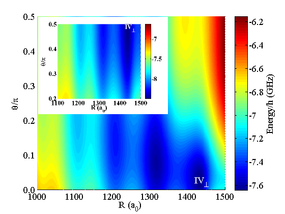
In Fig. 3(a) the complete two-dimensional -wave PES is shown as a function of () for G for radial distances . We observe a reflection symmetric potential surface with local potential minima at and .
In Fig. 3(b) the complete two-dimensional -wave PES is shown as a function of () for G for radial distances . We observe a potential surface with the global equilibrium positions at . This -wave PES provides bound rovibrational states. The region around is strongly affected by the level repulsion of the - and -wave PES as it has been described above. In Fig. 3(a) and 3(b) we see also that in this region the - and -wave PES strongly decreases and increases, respectively.
However, for and approaching or respectively, the effect of the - and wave level repulsion decreases for the - and -wave PES. For this effect vanishes completely, which is due to the fact that the Hamiltonian (3) then separates into a and block. The considered - and -wave curves arise due to the diagonalization of the subspace of the electronic problem (3). If we neglect the diamagnetic term in (3) the Zeeman interaction term does not couple the - and -wave curves because . Because of this the topology of the PES is unaffected by the applied magnetic field for .
V Potential energy surfaces
V.1 Parallel field configuration
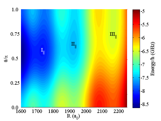
Let us begin with the analysis of the s- PES. We focus on the regime of field strengths G and . As presented in Greene00 the potential -wave PES is in the absence of any external field independent of . For a finite electric or magnetic field strength, this spherical symmetry is broken, which has been discussed in refs. Lesanovsky07 ; Kurz13 . In case of a vanishing electric field () the -wave PES provides a number of local minima which are taken on for the perpendicular configuration . In case of an electric field only () it forces the electron density to align in its negative direction, which leads to a higher density in the -direction. For this reason we find the global minimum of the -wave PES for the antiparallel field configuration at .
In case of finite parallel electric and magnetic field strengths we can tune the topology of the -wave PES between the pure electric and magnetic field limits. To be specific we choose G and vary the electric field strength . Fig. 4 presents the -wave PES for G, . We observe three local potential minima which we label with (), () and (). In case of we find these potential wells along the perpendicular configuration () with the radial minima position at , and respectively (see Fig. 3(a)). For the -wave potential well decreases monotonically for decreasing which is caused by the level repulsion described in Section IV. For finite electric field strengths the topology of the -wave PES changes in the sense that the angular positions of minima of the the potential wells (-) are shifted to higher values. This is clearly visible in Fig. 4. This effect is simply explained by the fact the electric field force the electron density to align in its negative -direction which is reflected in a deeper Born-Oppenheimer potential in this region. The radial positions of the minima are less strongly affected. With increasing electric field they are transferred to the final values (), () and () for . Furthermore, we see that the larger the radial position of the considered potential well from the ionic core the larger is the angular distance from . This feature can be understood in a semiclassical picture where we compare the Lorenz force with the electrostatic force on the electron. Since the Lorentz forces decreases with while remains constant. Therefore the electron density further away from the ionic rubidium core is more strongly affected by the electric field. In general the depth of the potential wells (-) strongly varies with the corresponding parameter values. In case of a dominant magnetic field ( G, ) the wells possess depths up to MHz. For a dominant electric field ( G, ) their depths are MHz.
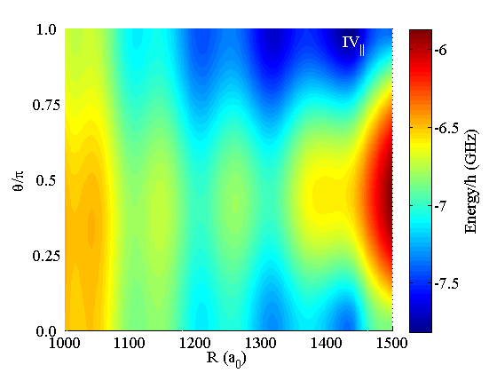
In Fig. 5 we present the -wave PES curve for G, . It possesses a global equilibrium position at denoted by . As described in Section IV in case of a pure magnetic field the -wave PES possesses a symmetry (see Fig. 3). A finite electric field along the -axis breaks this symmetry and tends, as above-mentioned, to enhance the electron density in the negative direction. As a consequence we find in case of the -wave PES the potential minimum at (Fig. 5). The depth of this potential well is approximately MHz and remains roughly constant for all considered field strengths.
V.2 Perpendicular field configuration
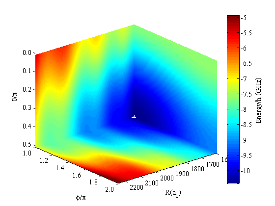
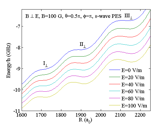
Fig. 6 we shows the three-dimensional -wave PES for the crossed field configuration G, as a function of . Because of the and symmetries (see Section III) we present the potential surface in the range of and . We clearly see an oscillating structure with local potential minima aligned into the negative -direction (). This can be understood by the fact the electric field simply deforms the azimuthaly symmetric PES for a finite magnetic field strength in the sense that it forces the electron density to align along the negative -direction. Due to this we obtain molecular states with a well-defined orientation antiparallel to the electric field. In contrast to the parallel field configuration the orientation of these molecular states cannot be tuned by varying the electric and magnetic field strengths. In the considered parameter range tuning the field parameters just changes the depth of the local potential minima at . This feature is shown in detail in Fig. 7 which presents one-dimensional potential cuts for the crossed field configuration. We have fixed the magnetic field strength to G and vary the electric field from in steps of . As already discussed in Section IV for we obtain no potential local wells, i.e. no bound states are provided for this magnetic field strength. With increasing electric field strength we again obtain local potential wells at the minima positions and respectively. Obviously, these values are very close to those obtained for the parallel field configuration (see previous subsection). Similar to the parallel field configuration we label the wells/plateaus with (), () and (). The radial equilibrium positions increase with increasing electric field strength up to (), () and (). As we observe in Fig. 7 the well () is affected most by the increasing electric field in the sense that its depth increases from up to MHz. Similarly the depths of the well () and () increase up to MHz () and MHz () respectively. We therefore conclude that the electric field counterbalances the effect of the -wave interaction and leads to bound states where otherwise none would have existed. This result is reminiscent of an effect already observed for the pure electric field configuration where the electric field stabilizes bound molecular states of the -wave PES Kurz13 as well. For dominant electric fields in the considered field regime the depths of the potential wells increase up to a value of approximately MHz.
In Fig. 8 we present a two-dimensional cut defined by through the -wave PES for the crossed field configuration for G, . As for the -wave PES in the parallel field configuration, we concentrate on the potential well providing the global equilibrium position. This well is labeled with . The radial equilibrium position is again given by for . In case of a pure electric field the single existing potential minimum is localized at which is shown in the inset of Fig. 8. By increasing the magnetic field strength the angular equilibrium position is shifted from to . This means the topology of the -wave PES changes from a single well to a double well PES. For all applied field strengths the depth of the well remains around MHz.
In Tab. 1 we summarize the topological properties for both field configurations in the limit of dominant electric and magnetic field strengths.
| , | , | , | ,() | ,, | ,, | ,, | ,, | |
| , | , | , | , | ,, | ,, | ,, | ,(), |
VI Rovibrational States
To analyze the rovibrational states for the parallel field configurations we introduce cylindrical coordinates () for the parametrization . We have , which means the azimuthal quantum number is a good quantum number. With this we write the rovibrational wave function which transforms the Hamiltonian (4) into
| (7) |
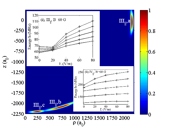
We solve the corresponding Schrödinger equation focusing on using a fourth order finite difference method for electric field strengths in the range and G. In Fig. 9 we present the ground state probability densities of the local potential well () in cylindrical coordinates (). We label the densities according to the applied field strengths with . For instance, (,c) indicates the probability density of the ground state in the well () with an applied electric field strength of . As described in Section V with increasing electric field strength the wells move from the configuration to the direction. This feature is clearly reflected in the position of the ground state probability densities. For field strengths beyond the position of the minimum of the well remains close to , as a result there are no qualitative changes of the corresponding ground state rovibrational probability densities. The latter can be characterized by their radial and angular extension . typical values observed are of the order of and (,c) up to (,b). We see that with increasing electric field strength from to the angular extension of the rovibrational probability densities in (,a) and (,b) increase as well. For higher field strengths the potential well () approaches and the angular extension of the probability density decreases again. This is clearly visible for (,c) in Fig. 9 and is caused by the potential term . In the inset (i) of Fig. 9 we present the the first five eigenenergies of the rovibrational states for the potential well () of the -wave PES, relative to the minimum of the potential well. The level spacing decreases to MHz for which can be explained by the minor decrease of the angular confinement. With increasing beyond a field strength of the potential gets affected by the centrifugal term in Eq. (7) and the angular confinement increases. This leads to a larger level spacing up to MHz as can be seen in the inset (i) of Fig. 9.
For the -wave PES the level spacing is of the order of MHz (see inset (ii) of Fig. 9). In case of the low-lying states it hardly varies with increasing field strength, only the higher excited states are affected in the sense that their level spacing increases from to MHz. This can be explained by the fact that enhancing the electric field strength increases the angular confinement which more strongly affects the higher excited states than the energetically low-lying ones.
In case of the crossed field configuration we have where and . Due to these symmetry properties the wave functions now obey and . To estimate the rovibrational level spacings we use the fact that the exact potential energy surfaces can be expanded around their equilibrium positions as
| (8) |
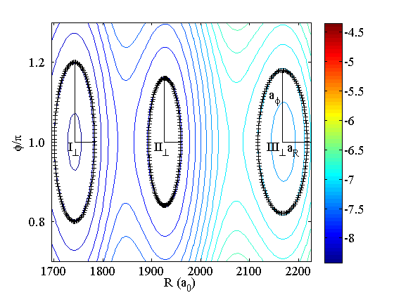
For small extensions in the angular directions the quantities , define together with a local Cartesian coordinate system. In these coordinates, Eq. (4) is reduced to three single harmonic oscillators providing level spacings and . In Fig. 10 we present such an approximation scheme for the G, crossed field configuration for the coordinates (). We clearly see that the harmonic approximation (crosses) fits the exact potential quite well. From this fit the frequencies of the harmonic oscillator can be extracted
| (9) |
where , and are the energy difference to the potential minimum and the fitted values for the semi-axis of the underlying ellipsoid. For the specific setup we find level spacings of MHz (), MHz () and MHz (). This means each potential well only provides up to one radial excitation. For the angular degrees of freedom we get MHz for all three potential wells. In case of the potential well for the -wave PES we obtain level spacings of the order of MHz in the radial and MHz, MHz in the angular degrees of freedom.
We remark that for both field configurations and - as well as -wave PES the radial as well as the angular level spacing strongly depends on the applied fields. The general level structure implies a single radial excitation ( MHz) with several angular excitations ( MHZ) on top. For both field configurations the states in the wells (-) and (-) of the -wave PES possess a finite lifetime due to a tunneling out of the local potential wells. These lifetimes strongly depend on the considered field strengths and we get maximal lifetimes in the order of microseconds.
VII Molecular Alignment and Orientation
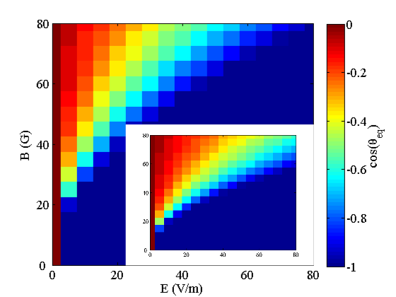
In Section V we presented the possibility to vary the topology of the molecular PES via tuning of the electric and magnetic fields. Obviously, this provides the possibility to control the molecular orientation and alignment. To quantify the orientation and alignment in case of the parallel field configuration we have to analyze the expectation value and the variance . The expectation values are taken with respect to the rovibrational state for the ground states in the potential wells (), () and (). The closer the absolute value of is to one, the stronger is the orientation of the state into the -direction and the closer is to zero, the stronger is the alignment of the state. We consider the ground state probability densities in the single wells to be strongly localized such that we can approximate the expectation values according to and where denotes the angular equilibrium position of the underlying potential well (see Fig. 9). In this approximation we get for the variance , which means that the degree of alignment is perfect. In Fig. 11 we present the dependence of of the ground state state of the potential well () on the applied field. The inset in this figure shows the same analysis but for the () well. We see that for pure magnetic and pure electric fields the state is oriented in a perpendicular (red region) and antiparallel (blue region) configuration, respectively. For both potential wells we find a crossover regime (yellow region) between these two configurations. We see that for fixed magnetic field strength the antiparallel configuration for the well () is achieved for lower electric field strengths than for (). This can be explained by the fact that the electric field stronger affects the states in the well () as compared to () (see Section V).
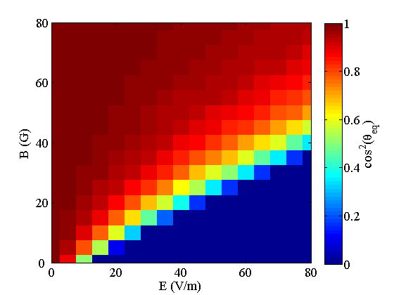
In case of the crossed field configuration the rovibrational Hamiltonian (7) possesses a reflection symmetry i.e. we get . In this case the molecular alignment is quantified by for ground rovibrational states. For the -wave PES we have molecular states with a well-defined perpendicular configuration of the internuclear axis with respect to the -axis. Here we have , which means they are antialigned with respect to the -axis. For the -wave PES and finite magnetic field strength we have potential surfaces with double well character. In this case the rovibrational states are delocalized over the double wells. In Fig. 12 we present the field-dependent alignment of the ground states in the corresponding potential well. We see that for pure electric and magnetic field configuration we have perfectly (anti)aligned molecular states. Similar to the molecular orientation for the parallel field configuration we find a crossover regime (yellow region) where the alignment changes from antialigned (blue region) to aligned states (red region).
VIII Electric dipole moment
Due to the impact on the molecular configuration the electric dipole moment can be readily tuned by changing the field strengths and specific field configuration. Let us analyze the dipole moments along the internuclear axis in the following
| (10) |
where denotes the unit vector along the internuclear axis.
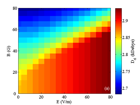
In Fig. 13 we show the electric dipole moment for the -wave PES for the parallel field configuration as a function of and . We observe that with increasing the dipole moment decreases while it increases for increasing . This can be understood by the fact that in the absence of any contact interaction and the reflection operations and are exact symmetries of the Hamiltonian (3). In the presence of the neutral perturber and the mixing of degenerate Rydberg states leads to an electric dipole given by the semiclassical approximation for a purely -wave interaction dominated PES. However, with increasing magnetic field the magnetic field terms become dominant and the corresponding symmetry properties get imprinted in the quantum states Lesanovsky07 . For a pure strong magnetic field case the -wave PES is approximately dominated by the hydrogen state which explains the decrease of the electric dipole moment. In case of an increasing electric field the electron cloud is more aligned into the negative field direction which causes the increase of .
Next we perform some (semi)analytical analysis to estimate the electric dipole moment. First we check the validity of the semiclassical approximation for finite electric and magnetic field strengths. As discussed in Section V for the considered field regimes the radial positions of the potential wells is only to a minor extent affected by the external fields (see Tab. 1). Therefore, we estimate the electric dipole moment as where denotes the mean value of the minimal and maximal radial positions for a considered potential well for varying field strength. For instance, for G, and for G, which gives and an approximate dipole moment of kDebye. This corresponds to a relative deviation of compared to the exact result, which means that in the considered parameter regime this simple estimate is quite accurate.
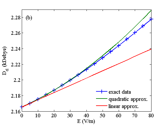
As discussed in Section V in case of the -wave PES its equilibrium position remains constant () with respect to a variation of the field strengths. In particular, in Section IV we have shown that the corresponding electronic eigenvector is independent of the applied magnetic field. Due to this we can reduce the analysis of the dipole moment of the -wave state to an arbitrary value of which we choose to be G. In Fig. 13(b) we show the electric dipole moment for the -wave PES for G as a function of . With increasing electric field strength grows quadratically. To verify this we present a corresponding semi-analytical result for the electric dipole moment where we expanded the state in a perturbative series up to the :
| (11) |
In this expansion indicate the field-free electronic states and are the expansion coefficients given by standard perturbation theory sakurai . Inserting this ansatz into (10) and keeping terms up to and we obtain the linear term (red) and quadratic term (green) approximations according to Fig. 13(b). We see that the exact data (blue line and crosses) are well approximated by the quadratic approximation. The semiclassical approximation gives a result of kDebye which deviates from the obtained data by . The larger deviation compared to the -wave state can be explained by the fact that the semiclassical approximation is originally derived for -wave interactions in the absence of any fields. Although we expect the -wave state to possess a strong -wave character far away from the region of avoided crossings () for the region of the localized potential well () the -wave character still provides a substantial contribution which explains the less accurate result for the resulting electric dipole moment.
For the crossed field configuration the electric dipole moments of the -wave PES potential wells (-) show a qualitatively similar behavior as their counterparts (-) in case of the parallel configuration. For all potential wells we find a decreasing dipole moment for increasing magnetic field strength and an increase of for an increasing electric field strength. In Tab. 2 we present the minimal () and maximal () value of the electric dipole moment (10) for the wells (-). As for the parallel field configuration we compare these results with the semiclassical approximation . With a maximal deviation of - the exact results are reproduced satisfactorily.
| 2.69 | 2.94 | 2.86 | |
| 3.25 | 3.39 | 3.34 | |
| 3.92 | 3.98 | 3.95 |
IX Conclusions
The recent experimental progress in preparing, detecting and probing the properties of non-polar ultralong-range Rydberg molecules Krupp14 ; Bendkowsky09 ; Pfaunat11 ; Bendkowsky10 ; Balewski13 has opened the doorway for a variety of possibilities to create novel species where atoms, molecules and even mesoscopic quantum systems are bound to Rydberg atoms. Therefore, the understanding and control of the properties of these hybrid Rydberg systems is of essential importance. Due to the high sensitivity of the weakly bound Rydberg electron the primarily choice to obtain electronic as well as rovibrational control is the application of external fields.
In this work we have therefore explored the effect of combined electric and magnetic fields on the polar high angular momentum molecular states for a parallel as well as a crossed field configuration. Taking into account both - and -wave interactions it turns out that for a pure magnetic field configuration strong level repulsion causes the potential wells which provide the trilobite states in the field-free case Greene00 to vanish. For this PES beyond a critical field strength of around G no bound states are provided anymore. For finite field strengths the angular degrees of freedom are converted from rotational to vibrational degrees of freedom, thereby rendering the field-free potential energy curve into a two- and three-dimensional energy surface for parallel and crossed field configurations, respectively. We obtain oscillatory potential curves with localization in the radial and angular degrees of freedom with depths up to hundreds of MHz providing a rich topology depending on the specific degree of electronic excitation and field configuration. The resulting rovibrational level spacings are in the order of several MHz. The parallel as well as the crossed field configuration provide unique ways to control the topology of the adiabatic potential energy surfaces. This directly leads to the possibility to control molecular orientation and alignment for the parallel and crossed field configuration, respectively. For instance, for parallel fields the molecular orientation can be tuned from a perpendicular to an antiparallel configuration by varying applied field strengths. In case of crossed fields the molecular alignment can be changed between an aligned and anti-aligned configuration with respect to the magnetic field. In addition, the topological control of the PES provides the possibility of directly controlling the electric dipole moment as well. Apart from numerical results we have provided also a semiclassical estimate and perturbative analysis of the electric dipole moment.
The plethora of interesting effects of high- ultralong-range Rydberg molecules in external fields keeps this particular species a promising candidate for future investigations. Because of its high sensitivity to small field strengths it is worth studying the dependence of molecular properties like electric and magnetic polarizabilities and susceptibilities. In case of Rydberg atoms these quantities strongly depend on the Rydberg excitation.
X Acknowledgment
We thank the Initial Training Network COHERENCE of the European Union FP7 framework for financial support.
References
- (1) R. Grimm, M. Weidemüler, and Y.B. Ovchinnikov, Adv. At. Mol. Opt. Phys. 42, 95 (2000)
- (2) R. Folman, P. Krüger, J. Schmiedmayer, J. Denschlag and C. Henkel, Adv. At. Mol. Opt. Phys. 48, 263 (2002)
- (3) C.J. Pethick and H. Smith, Bose-Einstein Condensation in Dilute Gases, Cambridge University Press (2008)
- (4) T. Köhler, K. Góral, and P.S. Julienne, Rev. Mod. Phys. 78, 1311 (2006)
- (5) I. Bloch, J. Dalibard, and W. Zwerger, Rev. Mod. Phys. 80, 885 (2008)
- (6) C. Chin, R. Grimm, P.S. Julienne, E. Tiesinga, Rev. Mod. Phys. 82, 1225 (2010)
- (7) S. Jochim, M. Bartenstein, A. Altmeyer, G. Hendl, S. Riedl, C. Chin, J. Hecker-Denschlag, and R. Grimm, Science 301, 2101 (2003)
- (8) S. Knoop, F. Ferlaino, M. Mark, M. Berninger, H. Schöbel, H.-C. Nägerl, and R. Grimm, Nature Physics 5, 227 (2009)
- (9) M. Repp et al., Phys. Rev. A 87, 010701(R) (2013)
- (10) C. H. Greene, A.S. Dickinson, and H.R. Sadeghpour, Phys. Rev. Lett. 85, 2458 (2000)
- (11) V. Bendkowsky, B. Butscher, J. Nipper, J.P. Shaffer, R. Löw, and T. Pfau, Nature 458, 1005 (2009)
- (12) E. Fermi, Nuovo Cimento, 11, 157 (1934)
- (13) A. Omont, J. Phys. (Paris) 38, 1343 (2011)
- (14) A.T. Krupp, A. Gaj, J.B. Balewski, S. Hofferberth, R. Löw, T. Pfau, M. Kurz and P. Schmelcher, Phys. Rev. Lett. 112, 143008 (2014)
- (15) I. Lesanovsky, H.R. Sadeghpour, and P. Schmelcher, J. Phys. B 39, L69 (2006)
- (16) M. Kurz and P. Schmelcher, Phys. Rev. A, 88, 022501 (2013)
- (17) M. Kurz, M. Mayle and P. Schmelcher, Europhys.Lett. 97, 43001 (2012)
- (18) M. Marinescu, H. R. Sadeghpour and A. Dalgarno, Phys. Rev. A 49, 982 (1994)
- (19) T.F. Gallagher, Rydberg Atoms, Cambridge Monographs on Atomic, Molecular and Chemical Physics, 1994
- (20) J. J. Sakurai, Modern Quantum Mechanics, page 285 ff., Addison-Wesley Publishing Company, 1994
- (21) W. Li, T. Pohl, J. M. Rost, S.T. Rittenhouse, H.R. Sadeghpour, J. Nipper, B. Butscher, J.B. Balewski, V. Bendkowsky, R. Löw, and T. Pfau, Science 334, 1110 (2011)
- (22) V. Bendkowsky et al., Phys. Rev. Lett. 105, 163201 (2010)
- (23) J. B. Balewski et al., Nature 502, 664 (2013)