Rayleigh scattering in coupled microcavities: Experiment
Abstract
We experimentally analyze Rayleigh scattering in coupled planar microcavities. We show that the correlations of the disorder in the two cavities lead to inter-branch scattering of polaritons, that would otherwise be forbidden by symmetry. These longitudinal correlations can be inferred from the strength of the inter-branch scattering.
I Introduction
In the last two decades, microcavity polaritons have proved a valuable testbed in the investigation of a number of interesting phenomena, such as non-equilibrium condensation Kasprzak et al. (2006); Balili et al. (2007), superfluidity Amo et al. (2009); Cristofolini et al. (2013), lasing Weihs et al. (2003); Nelsen et al. (2009), parametric oscillations Savvidis et al. (2000); Tartakovskii et al. (2002); Giacobino et al. (2005), soliton formation Hivet et al. (2012); Sich et al. (2014) to name but a few. A recent review of the experiments and related theory can be found in Carusotto and Ciuti (2013). Polaritons emerge as the eigenstates of strongly coupled quantum well excitons, and photons of a planar cavity of length of the order of the wavelength of light. Given that the system possesses two-dimensional translational invariance, both the photon, and exciton modes can be described by the in-plane momentum, and consequently, photons with a given momentum will couple to excitons with the same momentum. It is also worth noting that in single cavities, the polariton branches are not degenerate anywhere.
The structural disorder induced by the fabrication process results in fluctuations of the exciton and photon potentials; the translational symmetry is broken. This gives rise to coherent resonant Rayleigh scattering (RRS) of the polaritons. While initially RRS was regarded an unwanted feature, later it was realized that useful information can be gained about the structural defects by studying the properties of the scattered light Langbein (2010). It was pointed out as well that the instantaneous and polarization-conserving scattered light can be utilized in testing for superfluidity Carusotto and Ciuti (2004); Christmann et al. (2012); Amo et al. (2009).
In a single cavity, given the isotropic polariton dispersion relations, the resonant nature of the scattering leads to an annular RRS emission in the far field Freixanet et al. (1999); Houdré et al. (2000); Langbein and Hvam (2002). The wave vectors of the final states populating the emission ring have the same length.
Rayleigh scattering has been well known from experiments with quantum wells (QW), where it was used to probe potential fluctuations Langbein et al. (1999). As a consequence, in early theoretical studies of RRS of polaritons, it was assumed that the disorder in the quantum wells is the main cause Whittaker (2000); Shchegrov et al. (2000).
Several experimental results, however, gave strong indication that the dominant contribution comes from the photonic part of the polaritons. Gurioli et al., e.g., observed RRS at large negative detuning, where the polariton is predominantly photonic Gurioli et al. (2001). More recently, Maragkou et al. demonstrated RRS in a purely photonic cavity Maragkou et al. (2011). In several experiments, it has also been found that RRS produces a cross-shaped pattern in addition to the well-known ring. This feature was explained by a growth-induced cross-hatch pattern in the cavity mirrors, underlining once more that RRS is caused by the photonic component of polaritons Gurioli et al. (2001); Langbein and Hvam (2002); Langbein (2004); Zajac et al. (2012).
It is not clear a priori, what the emission pattern will be, if polariton branches can be arranged in a way that they are degenerate: in such a case, the resonance condition could be satisfied by states that might belong to different symmetry classes, leading to multiple concentric rings in the far field. In particular, in a double cavity, due to the reflection symmetry with respect to the mirror between the two cavities, these branches possess, in increasing order of the energy, even, odd, even, and odd parity, and as a consequence, scattering would be allowed only from the first to third, and second to fourth branches, but these pairs are not degenerate.
Recently, inter-branch Rayleigh scattering has been observed in a triple cavity where the splitting of the three cavity modes and strong exciton-photon coupling at the same time gives rise to six polariton branches Abbarchi et al. (2012). The experimental findings were interpreted using structural data gained by scanning electron microscope and X-ray diffraction measurements. In detail, it was demonstrated that a periodic modulation induced by growth manifests itself in scattering into preferred directions in momentum space. However, in these experiments, polaritons were injected with zero momentum, and this configuration does not allow for the simultaneous study of inter- and intra-branch scattering.
In this paper, we will study polariton RRS in a coupled double cavity. We will focus on an experimental configuration where polaritons are injected at an in-plane momentum that allows observation of inter- and intra-branch scattering at the same time.
II Experiment
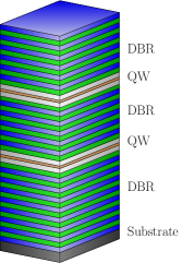
The double cavity system, grown by molecular beam epitaxy, can be seen on the left hand side of Fig. 1. Two cavities each containing 4 70- GaAs quantum wells are coupled via an intermediate distributed Bragg reflector (DBR). The top and bottom DBRs consist of 16 periods of layers, while coupling between the cavities is mediated by a mirror of 15.5 layer pairs of the same constitution. The coupling leads to a cavity mode splitting of 8 meV, which was determined from white-light reflection measurements. When the cavity modes are brought into resonance with the quantum well excitons, four polariton branches form. From white-light spectra, and with the help of the standard transfer matrix approach, we deduced a Rabi splitting of about 5 meV. The quantum well exciton resonance is at 1607.7 meV.
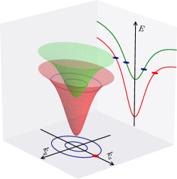
The particular scattering process in which we are interested is shown on the right hand side of Fig. 1: the system is pumped on either of the two lower branches (energetically both below the exciton line). The two resonant circles of the far-field luminescence can be seen on the vertical projection, while the horizontal projection shows the two branches as seen on a spectrometer (c.f. Fig. 3 below).
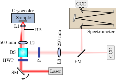
Our experimental setup can be seen in Fig. 2. During measurements, the sample was held at a temperature of 15 K using a Gifford-McMahon-type cryocooler. We would like to point out that we could obtain qualitatively similar results even at 77 K, but the evaluation of data becomes difficult. First, excitons become ionized, hence, polariton states are not very well defined, and second, the phonon-induced background is much more dominant at those high temperatures. The microcavity was resonantly excited by linearly polarized light from a tunable Ti:Sapphire laser. In order to avoid non-linear effects, intensities were kept at an average of 2 (approximately 200 ), and we checked that a further reduction in the power does not result in changes of the relative scattered intensities. An aspherical lens (L1) with a numerical aperture of 0.82 was used for both focusing the laser light onto the sample, and collecting emission. On the sample, we directly measured a focal spot size of about 30 m with a Gaussian intensity distribution. Far-field imaging was carried out by means of a commercial CCD camera and a lens system consisting of two lenses with focal lengths 500 (L2), and 200 mm (L3), respectively. An imaging spectrometer in combination with a second CCD was used for spectral analysis. For better contrast, the reflected pump beam was blocked by a small metal stripe (BB) inserted in the back focal plane of the aspherical lens. In addition, we detected the emission from the sample in the linear polarization basis cross-polarized to the pump.
III Results and discussion
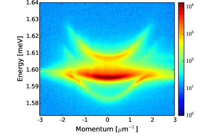
A typical dispersion with the four polariton branches can be seen in Fig. 3. In this case, the sample was probed by off-resonant excitation at 633 nm, and we collected the luminescence. Note that the third polariton branch is hardly visible.
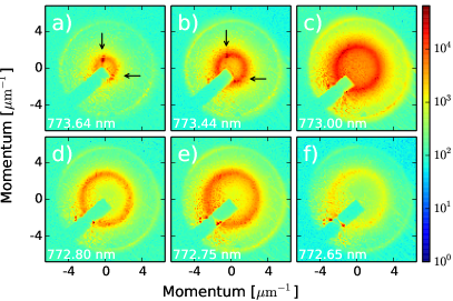
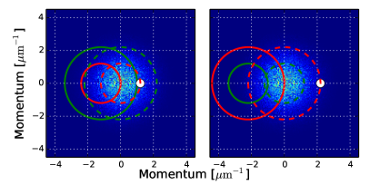
Exemplary RRS far field images are shown in Figs. 4-5. In these plots, the excitation position was fixed at a point, where the cavity detuning is -10.1 meV, and we changed the excitation energy. The momentum was adjusted in a way that the laser light was always resonant with one of the polariton branches. In the first series (Fig. 4) the excitation was on the second branch (inner circle).
The resonant scattering gives rise to two rings, whose radii are dictated by the local dispersion relations. The first ring results from scattering into polariton states on the branch that is pumped, and it is equivalent to the usual Rayleigh scattering in single cavities: owing to the isotropic dispersion, the process conserves the absolute value of the momentum. The second ring is generated by inter-branch scattering, and is peculiar in the sense that the absolute value of the momentum is no longer conserved. In Fig. 4(a-b), one can also recognize a vertical and horizontal line intersecting at the position of the pump momentum. Given that they are parallel to the crystal axes, these lines can be attributed to the cross-hatch dislocation mentioned earlier Zajac et al. (2012).
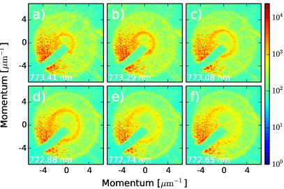
Pumping with the same power on the first branch (outer ring, Fig. 5) leads to a similar emission pattern where again the two RRS rings are visible, as shown in Fig. 5. We should note, however, that the overall intensities are reduced compared to Fig. 4.
The interpretation of inter-branch scattering observed in our samples is that in the presence of disorder, momentum is not a good quantum number, and, in the first approximation, the scattering process can be described by Fermi’s golden rule, which contains a constraint on the energy for the transition probabilities. It is interesting to note that without disorder, the two branches have even/odd parity caused by the reflection symmetry of the cavities, and inter-branch scattering would be forbidden by the symmetry. Therefore, disorder is responsible for breaking not only the translational, but also the reflection symmetry of the system. It can be shown that, if the disorder potential in the two cavities is correlated/anti-correlated, the intra/inter-branch scattering is suppressed. A thorough theoretical treatment of this problem is given elsewhere Vörös and Weihs (2014).
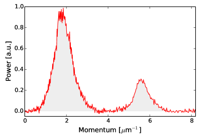
These results can be made more quantitative by comparing the luminescence powers of the two rings. As long as non-linear effects can be ruled out (low excitation power), the relative intensities are independent of the pump power, and are only a function of the photonic disorder potentials in the two cavities. In Fig. 6, we show the azimuthally integrated power as a function of the absolute value of the momentum. The origin of the polar coordinate system was determined by first visually fitting a circle on the inner ring. However, as long as the two rings are well-separated (which is the case for all our measurements), the exact position of the origin is not crucial: the measured intensities for each ring will be the same, only the profiles change slightly. The intensities were normalized to a maximum of 1. The two peaks corresponding to the two Rayleigh rings are clearly identifiable. The shaded areas denote the range over which we integrated the power to measure the total scattering rate in subsequent figures.
In Fig. 7 we plot the ratio of the powers for three positions on the sample as a function of the pump momentum. The detuning was the same for all three points. The power ratio was defined as the total power of the outer ring divided by the total power of the inner ring, as shown in Fig. 6. In this case, we excited on the inner ring (second branch). The laser wavelength was adjusted to match the polariton dispersion for each momentum, and we recorded 5 images for each case. The displayed data points are the average of the 5 measurements. The three curves run close to each other, and they obey a general slightly increasing trend as the momentum increases, but there are some local variations.
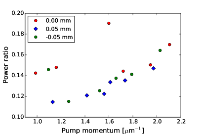
The physical reason for a change in the scattering amplitudes is the following. By Fermi’s golden rule, the transition probabilities are proportional to the square of the matrix elements taken at the difference wave vector. The matrix elements themselves are the Fourier transforms of the scattering potential. Now, for technical reasons, the disorder potential usually has some transverse correlation whose Fourier transform displays a maximum at zero momentum. The transition probabilities, and hence, the power of the Rayleigh rings can be obtained by integrating this Fourier transform over all allowed wave vectors, i.e., over the circle of difference wave vectors as shown in Fig. 8. When the pump momentum changes, so does the radius of the scattering ring, and thus, a different domain of the Fourier transform will be sampled. This leads to a different intensity distribution, and different total power.
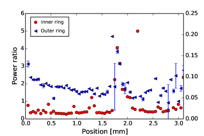
In Fig. 9, we plot the dependence of the relative power on the spatial coordinate for two cases, once when the sample is pumped on the inner ring, and once on the outer ring. The measurement points were chosen along a line perpendicular to the wafer’s gradient, so as to keep the detuning constant. The first measurement position was taken as the reference point of the coordinate system.
The two curves display similar behavior: apart from small variations, and a slight and smooth overall change, there is a well-defined maximum at position 1.75 mm. It is also worth noting that the outer ring, as in Figs. 4-5, is generally dimmer (the power ratio is smaller than 1) than the inner ring.
It can be shown that the amount of inter-branch scattering is related to the inter-cavity correlations of the disorder potential Vörös and Weihs (2014). One might ask, why these correlations would develop in the first place, if the disorder is truly random. The transverse correlations are related to the spatial distribution of material beams in the epitaxy equipment. It can be expected that, if the beam is not completely uniform in space, then any irregularities will vanish over a finite distance Savona (2007). By the same token, since the cavities are grown sequentially in time, the longitudinal correlations reveal information about the long-term stability of the deposition process. Again, it is reasonable to expect that some deviations from the average deposition rate will be sustained over longer periods of time, simply because they are related to long-term parameters (e.g., geometry, pressure/temperature distribution, target positions) of the fabrication system. This also implies that the disorder in the two cavities will probably be correlated, and not anti-correlated.
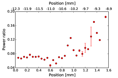
In Fig. 10, we plot the inter-branch scattering power as a function of the detuning. (We defined detuning as the energy difference between the exciton, and the uncoupled photon state. This latter one is the mean of the coupled photon energies.) In this case, the excitation spot was shifted along the wafer’s gradient, while the excitation energy was kept constant at 1603.66 meV, and the excitation momentum was always adjusted to match the polariton resonance. In principle, the detuning should not influence the strength of inter-branch scattering. Since RRS is caused by photonic disorder, its strength will be proportional to the photon content of the particular polariton state. However, this depends on the Hopfield coefficients, which are simply a function of the energy difference between the state in question, and the exciton’s energy Einkemmer et al. (2013). Therefore, for resonant phenomena, only the absolute scattering amplitude depends on the energy, but not the relative powers. For this reason, any change in the relative intensities should be regarded as a change in the longitudinal correlations, and not as an effect of the detuning. In Fig. 10, we recognize an increase in inter-branch scattering for smaller red detuning, which also happen to lie farther from the center of the wafer. While the trend may not be significant, it could indicate increasing disorder correlation.
IV Conclusion
In conclusion, we have presented an experimental study of polariton Rayleigh scattering in coupled microcavities. We have shown that the photonic disorder that breaks both the translational and reflection symmetry of the system re-distributes the polaritons to two branches, and this results in two concentric emission rings in the far field. The absolute value of the initial momentum is conserved only on one of the branches. We also argued that by inspecting the relative scattered intensities on the two rings, one can infer the long-term stability of the deposition process.
Acknowledgements.
The authors gratefully acknowledge financial support from the Austrian Science Fund, FWF, project number P-22979-N16.References
- Kasprzak et al. (2006) J. Kasprzak, M. Richard, S. Kundermann, A. Baas, P. Jeambrun, J. Keeling, F. Marchetti, M. Szymańska, R. André, J. Staehli, V. Savona, P. Littlewood, B. Deveaud, and L. Si, Dang, Nature 443, 409 (2006).
- Balili et al. (2007) R. Balili, V. Hartwell, D. Snoke, L. Pfeiffer, and K. West, Science 316, 1007 (2007).
- Amo et al. (2009) A. Amo, J. Lefrére, S. Pigeon, C. Adrados, C. Ciuti, I. Carusotto, R. Houdré, E. Giacobino, and A. Bramati, Nature Physics 5, 805 (2009).
- Cristofolini et al. (2013) P. Cristofolini, A. Dreismann, G. Christmann, G. Franchetti, N. Berloff, P. Tsotsis, Z. Hatzopoulos, P. Savvidis, and J. Baumberg, Phys. Rev. Lett. 110, 186403 (2013).
- Weihs et al. (2003) G. Weihs, H. Deng, R. Huang, M. Sugita, F. Tassone, and Y. Yamamoto, Semiconductor Science and Technology 18, S386 (2003).
- Nelsen et al. (2009) B. Nelsen, R. Balili, D. Snoke, L. Pfeiffer, and K. West, Journal of Applied Physics 105, 122414 (2009).
- Savvidis et al. (2000) P. Savvidis, J. Baumberg, R. Stevenson, M. Skolnick, D. Whittaker, and J. Roberts, Phys. Rev. Lett. 84, 1547 (2000).
- Tartakovskii et al. (2002) A. Tartakovskii, D. Krizhanovskii, D. Kurysh, V. Kulakovskii, M. Skolnick, and J. Roberts, Phys. Rev. B 65, 081308 (2002).
- Giacobino et al. (2005) E. Giacobino, J.-P. Karr, A. Baas, G. Messin, M. Romanelli, and A. Bramati, Solid State Communications 134, 97 (2005).
- Hivet et al. (2012) R. Hivet, H. Flayac, D. Solnyshkov, D. Tanese, T. Boulier, D. Andreoli, E. Giacobino, J. Bloch, A. Bramati, G. Malpuech, and A. Amo, Nature Physics 8, 724–728 (2012).
- Sich et al. (2014) M. Sich, F. Fras, K. Chana, S. Skolnick, N. Krizhanovskii, V. Gorbach, R. Hartley, V. Skryabin, S. Gavrilov, A. Cerda-Méndez, K. Biermann, R. Hey, and V. Santos, Phys. Rev. Lett. 112, 046403 (2014).
- Carusotto and Ciuti (2013) I. Carusotto and C. Ciuti, Rev. Mod. Phys. 85, 299 (2013).
- Langbein (2010) W. Langbein, La Rivista del Nuovo Cimento 33, 255 (2010).
- Carusotto and Ciuti (2004) I. Carusotto and C. Ciuti, Phys. Rev. Lett. 93, 166401 (2004).
- Christmann et al. (2012) G. Christmann, G. Tosi, N. Berloff, P. Tsotsis, P. Eldridge, Z. Hatzopoulos, P. Savvidis, and J. Baumberg, Phys. Rev. B 85, 235303 (2012).
- Freixanet et al. (1999) T. Freixanet, B. Sermage, J. Bloch, J. Marzin, and R. Planel, Phys. Rev. B 60, R8509 (1999).
- Houdré et al. (2000) R. Houdré, C. Weisbuch, R. Stanley, U. Oesterle, and M. Ilegems, Phys. Rev. B 61, R13333 (2000).
- Langbein and Hvam (2002) W. Langbein and J. Hvam, Phys. Rev. Lett. 88, 047401 (2002).
- Langbein et al. (1999) W. Langbein, J. Hvam, and R. Zimmermann, Phys. Rev. Lett. 82, 1020 (1999).
- Whittaker (2000) D. Whittaker, Phys. Rev. B 61, R2433 (2000).
- Shchegrov et al. (2000) A. Shchegrov, J. Bloch, D. Birkedal, and J. Shah, Phys. Rev. Lett. 84, 3478 (2000).
- Gurioli et al. (2001) M. Gurioli, F. Bogani, D. Wiersma, P. Roussignol, G. Cassabois, G. Khitrova, and H. Gibbs, Phys. Rev. B 64, 165309 (2001).
- Maragkou et al. (2011) M. Maragkou, C. Richards, T. Ostatnický, A. Grundy, J. Zajac, M. Hugues, W. Langbein, and P. Lagoudakis, Optics Letters 36, 1095 (2011).
- Langbein (2004) W. Langbein, Journal of Physics: Condensed Matter 16, S3645 (2004).
- Zajac et al. (2012) J. Zajac, E. Clarke, and W. Langbein, Appl. Phys. Lett. 101, 041114 (2012).
- Abbarchi et al. (2012) M. Abbarchi, C. Diederichs, L. Largeau, V. Ardizzone, O. Mauguin, T. Lecomte, A. Lemaitre, J. Bloch, P. Roussignol, and J. Tignon, Phys. Rev. B 85, 045316 (2012).
- Savona (2007) V. Savona, Journal of Physics: Condensed Matter 19, 295208 (2007).
- Vörös and Weihs (2014) Z. Vörös and G. Weihs, arxiv (2014).
- Einkemmer et al. (2013) L. Einkemmer, Z. Vörös, G. Weihs, and S. Portolan, arxiv , 1305.1469 (2013).