∎
Modeling radiation in particle clouds: On the importance of inter-particle radiation for pulverized solid fuel combustion
Abstract
The importance of inter-particle radiation for clusters of gray and diffuse particles is investigated. The radiative cooling of each individual particle is found to vary strongly with its position in the cluster, and a “mean” radiative particle cooling term is proposed for single particle simulations of particle clusters or for high detail simulation, like Direct Numerical Simulations of small sub-volumes of large clusters of particles. Radiative cooling is shown to be important both for furnaces for coal gasification and coal combustion. Broadening the particle size distribution is found to have just a minor effect on the radiative particle cooling. This is particularly the case for large and dense particle clusters where there is essentially no effect of size distribution broadening at all. For smaller and more dilute particle clusters, the effect of distribution broadening is clear but still not dominant.
Keywords:
combustioncoalradiationsimulationparticle1 Introduction
Many industrial processes, such as e.g. pulverized coal or biomass combustors, fluidized bed reactors or entrained flow reactors rely on reacting particles. In order to fully understand these systems, an understanding of the chemical reactions together with the heat transport to and from the particles is crucial. In most cases, convective and conductive heat transfer between the particles and the gas must be considered. For high temperatures, radiative heat transfer should also be taken into account. Here one can think of both particle-fluid interactions, particle-wall interactions and particle-to-particle interactions. In the work reported here, the importance of particle-to-particle radiation is discussed.
When performing CFD simulations, particle radiation is often included and found to be important azad1981 ; park1998 ; boutoub2007 . If, on the other hand, one does not perform a full CFD simulation but is rather interested in solving single particle physics and chemistry in high detail one often neglects, or partly neglects, radiation. In such cases radiation may not be considered at all, or if it is taken into account, only particle-wall radiation qiao12 ; xu12 ; mitchell07 or particle-fluid radiation liu01 is considered. The primary aim of this paper is to obtain a realistic description for the particle radiation transfer, including both particle-to-wall and particle-to-particle radiation, that can be used for high detail particle simulations. The secondary aim is to investigate the effect of particle size distribution broadening on radiative transfer.
In the current work, only geometric scattering is considered, and the analysis is limited to the case where the particles radiate like graybodies and the gaseous environment between particles is transparent to radiation. Considering only geometric scattering is valid since the particles have large size parameters, i.e. where is the wavelength of the radiation and is the particle radius, such that Rayleigh and Mie scattering can be omitted.
Consider a cloud of hot particles embedded in a radiatively transparent gas and enclosed within a confinement. This could for example resemble the situation in an entrained flow gasifier. If the radiative flux absorbed by a particle is and the flux absorbed by a replacement blackbody particle having the same size and temperature is , then an absorption efficiency factor for the particle can be defined as , which is a measure of the efficiency of the particle as an absorber compared to that of a blackbody.
A ray of radiation incident on a large particle will either be absorbed or reflected by the particle surface. Since the total cross section of a particle with radius is , the absorption cross section must be given that a fraction of all the radiation incident on the particle is absorbed. Since radiation is either absorbed or reflected the scattering cross section of the particle must be . A scattering efficiency factor is defined, analogously to the absorption efficiency factor, as the fraction of incident radiation that is scattered by the particle surface , which then yields . For the large particles of interest, the scattering efficiency factor equals the reflectivity of the particle surface while the absorption efficiency factor equals the absorptivity of the particle surface. In all of the following the scattering efficiency factor of the particles is assumed to be much smaller than the absorption efficiency factor such that the effect of scattered radiation from the particles can be neglected.
Performing three dimensional CFD simulations of full gasifiers or combustors are very demanding. Due to the large CPU power required one often has to use very simplified chemical models, both for the homogeneous and heterogeneous reactions. In many situations it is therefore better to simulate one single particle with high fidelity chemistry, and let this particle represent the “average” particle in the domain. With this simulation method one can easily do a large parameter scan over a range of different parameters with detailed chemical reactions. Such an “average particle” simulation will not yield detailed information of geometrical features in any application. Instead it will yield qualitative trends, using accurate chemical kinetics, for a range of parameters in “typical” conditions relevant for the application of interest. Traditionally, the particle cooling term used for such single particle simulations of a cloud of particles has been given by qiao12 ; mitchell07
| (1) |
where and are the thermal radiation from the particle and the wall, respectively. It is evident from this that inter-particle radiation is neglected, which may not be a good assumption for many applications. A description of a particle cooling term that does include inter-particle radiation for this kind of simulation tool does not exist in the open literature. The main objective of the current work is therefore to extend the above radiative cooling term to also take into account inter-particle radiation.
2 The extinction coefficient for a cloud of particles
The extinction coefficient is a measure of how easily a ray of radiation penetrates a given medium without being absorbed. Let a large number of small particles be embedded in the fluid such that the number density of the particles with radius between and is . If the particles are treated as diffuse graybodies with zero scattering coefficients, a ray of radiation emitted from the source at may be absorbed by the particles. The probability of extinction depends on the number density of particles, the projected particle surface area and the length of travel. The extinction coefficient, , of the medium due to the embedded particles is given by
| (2) |
Let’s now assume a Gaussian particle size distribution given by
| (3) |
where is the total particle number density, is the mean particle radius and is the width of the particle size distribution. It is convenient to define the distribution width as a fraction of the mean particle radius , i.e. . Employing this in Eq. (3), and using the result in Eq. (2) yields the following expression for the extinction coefficient
| (4) |
The equation of radiative transfer, which describes the change in spectral radiative intensity with around the wavelength in the solid angle about the direction of , is given by
| (5) | |||||
where is the phase function for scattering, is the spectral intensity from a blackbody and and are the spectral absorption and scattering coefficients, respectively. For a medium in which only absorption is important, and where the absorption coefficient is assumed to be constant for all wavelengths, the equation of radiative transfer reduces to
| (6) |
By neglecting emission along the path the spectral intensity of radiation after traveling a distance into a medium is then found by integration of Eq. (6) to be
| (7) |
Here is the intensity at the beginning of the path, the spectral intensity leaving a char particle, which is assumed to be a graybody emitter. For such radiation, the total intensity at a distance from the particle is found by integrating over all wavelengths
| (8) |
Here, is the particle emissivity, is Stefan-Boltzmann constant and is the particle temperature. Particle scattering has been neglected since for most relevant applications . Later in the paper, the emission from each particle will be included through an integration over spherical shells of increasing radius instead of through a direct inclusion in the equation of radiative transfer. This does not result in any loss of generality and is done in order to simplify the calculations.
The radiant energy per unit time in the small wavelength interval centered around that is incident on a surface element and originates from a surface element on the surface of a particle having a center a distance away from is given by
| (9) |
where is the solid angle subtended by when viewed from and is given by
| (10) |
Here is the distance between the differential elements and and and are the angles between the straight line connecting and and the normal to () and (), respectively. Shown in Fig. 1 is a schematic view of the variables. Due to the curvature of the particle surface the distance between and will generally be slightly different from and is denoted .

The total energy from the particle incident on per time unit is found by integrating over all wavelengths and over the entire surface, , of the particle;
| (11) |
where will vary with due to the curvature of the particle surface. By assuming that , it follows that and that becomes the angle between and the line connecting the center of the particle and . Now, by using Eq. (8), it can be found that
| (12) |
The flux at due to radiation from the entire particle is now
| (13) |
where the radiative flux emitted from the surface of a particle is
| (14) |
Assume now that corresponds to the projected surface area of some particle pc with radius and external surface are . The total emission on pc is then , while , such that the mean flux onto the surface of pc due to a particle with radius placed a distance away from pc is
| (15) |
3 Solid-Solid radiation
3.1 Particle-wall radiation
Let’s now assume that we are in a spherical confinement with radius . The non-dimensional number is the optical thickness. In the case with negligible optical thickness (i.e. ) the total radiative flux incident on the confinement wall due to the radiation from all particles is
| (16) |
where the first term in the numerator yields the total number of particles within the confinement and the second term give the emission from each of these particles. Since negligible optical thickness is assumed, it is clear that all radiation that is emitted from the particles will eventually be incident on the wall, which explains why the denominator must equal the surface area of the confinement wall in order to yield the radiative flux on the wall.
In the case of non-negligible optical thickness, the equation for the total radiative flux on the confinement walls is more complicated. Booth booth49 theoretically considered a cloud of radiating particles in order to determine an effective emissivity that could be used to describe radiation from the particle cloud. He showed that by assuming an absorption efficiency factor of unity, the radiative emission incident on the walls surrounding the cloud, due to the enclosed particle cloud, is
| (17) |
where
| (18) |
From this it is clear that the cloud of particles within the enclosure may be considered as a single object with radius , temperature and an effective emissivity . For very small values of the optical thickness, it can be shown by Taylor expansion that
| (19) |
such that in the case of vanishing , Eq. (17) reduces to Eq. (16), as expected.
4 Particle energy equation
The energy conservation equation for a particle is given by
| (20) |
where is the particle temperature, is the particle mass, is the specific heat capacity of the particle and and represent the heating/cooling due to radiation and convection and conduction, respectively, and represent any other heating term that could be due to e.g. chemical reactions. The effect of radiative absorption may be very important for the temperature evolution of a particle, but exactly how important the absorption is will depend on the position of the particle within the particle cluster.
4.1 Particle in the center of the enclosure
At the end of Sec. 2, was defined as the mean flux at the surface of a particle due to the radiative emission from another particle with radius a distance away. The total flux received by a particle in the center of the enclosure, , is now found by integrating over all its surrounding particles. This means by integration over all particle volumes and number densities , i.e.
| (21) |
Since the volume of a spherical shell with thickness and radius is , and since the particle number density of particles having radii between and is given by , the above equation becomes
| (22) |
when Eq. (15) is used for and all particles are assumed to behave alike.
The flux of radiation from the enclosure walls incident on the particle in the center of the enclosure is
| (23) |
where the radiative flux emitted from a diffuse graybody wall is
| (24) |
and where the wall temperature and emissivity are given by and , respectively. The radiative flux reflected off the wall, , is given by the product of the radiative flux received from the particles and the reflectivity of the wall, , i.e.:
| (25) |
where is given by Eq. (17).
The radiative cooling of the particle in the center of the particle cloud, , is found by integrating the difference between the absorbed, , and the emitted, , radiative flux over the particle surface of the particle in the center of the particle cloud. The radiative flux emitted from the particle is given by , where is found from Eq. (14), while the radiative flux received by the particle in the center of the cloud is given by the sum of the radiation received from the rest of the particle cloud and the wall, i.e. . Since the radiation in the center of the spherical cloud is isotropic, such that the integration over the particle surface can be replaced by the external particle surface area, this yields
| (26) |
where is the surface area of the particle. By employing Eq. (22), Eq. (23) and Eq. (26) the radiative cooling term of the particle in the center of the particle cloud becomes
| (27) |
4.2 Particle near the enclosure
A particle very near the enclosure walls will receive the radiative flux from all the other particles on one side while on the other side it will receive the flux from the wall. The mean flux received is therefore which yields
| (28) |
4.3 The “mean” particle
In the following, a radiation term that on average will give the correct net radiative outflow from the “average” particle in the cloud, is proposed. The radiative term, , is defined as the net radiative flux from the entire particle cloud divided by the total number of particles in the cloud.
Since the gas is assumed not to take part in the radiative exchange, and the container wall is assumed to be opaque, the only two radiatively active media are the particle cloud and the container wall. The net radiative heating of the wall, , equals the radiation absorbed by the wall from the particles, minus the radiation from the wall which is absorbed by the particles. Similarly the net radiative heating of the particles, , equals the radiation absorbed by the particles from the wall, minus the radiation from the particles which is absorbed by the wall. Based on this a radiative balance equation between the two media can be set up:
| (29) |
Note that the above equation does not consider the energy balance of the system, it only states that the net radiative heating of the wall and the particles must sum to zero.
Since all surfaces are assumed to be gray and diffuse and since all particles are assumed to behave alike, the absorptivity of the particle cloud equals the effective emissivity found in Eq. (18), , such that the total thermal emission from the wall incident on the particle cloud is
| (30) |
The net radiative heating of the wall equals the radiative energy the wall absorbs from the particle cloud minus the radiative energy it emits as thermal radiation, i.e.
| (31) |
when and is the absorptivity of the wall. By using Eq. (17), Eq. (30) and Eq. (31), it is found that the net radiative heating of the wall is
| (32) |
In the beginning of this subsection the radiative cooling term of the average particle was defined as the net radiative flux from the entire particle cloud divided by the total number of particles in the cloud. This means that the integral of over all particles in the cloud must equal the negative of the net radiative heating of the particle cloud. From this it is now clear that is found by
| (33) |
when the cloud volume is given by . When using the relation
| (34) |
together with Eq. (2), the integral in Eq. (33) is found to be
| (35) |
Combining Eq. (35) and Eq. (33) to eliminate the integral, and inserting the resulting expression for into Eq. (34) yields
| (36) |
Introducing Eq. (29) and Eq. (32) into the above results in the following expression for the net radiative outflow from the “average” particle
| (37) |
since the optical depth of the enclosure is given by . We propose that the use of this average radiative loss better approximates the radiative loss of a particle in a particle cloud of particles compared to previous methods neglecting the inter-particle radiation (Eq. (1)). The proposed method is not applicable for CFD simulations of entire combustors or reactors, where ordinary radiation models like e.g. the discrete ordinates method or similar can be used. Instead the proposed equation is particularly useful when one is not able to explicitly simulate the radiation from the full particle cloud but instead focus on a single particle that is supposed to represent all the other particles. This is the case in the work of e.g. Qiao et al. qiao12 and Mitchell et al. mitchell07 . The proposed radiative cooling term will also be applicable when Direct Numerical Simulations (DNS) are being used to simulate a very small sub domain of a real application111In a DNS all spatial and temporal scales of the fluid are fully resolved, hence the fundamental fluid equations can be solved without any modeling of the fluid equations. This yields very accurate and reliable results, but it requires huge computational resources. With a DNS, even on the worlds largest computers, only small physical domains can therefore be considered. Note that for a typical DNS the embedded particles are assumed to be very small, and hence are not resolved. This means that even though the fluid itself can be solved without any modeling, the fluid-particle coupling must be based on models, such as e.g. the Stokesian drag law. . This is particularly so due to the small volumes realizable in a DNS simulations, which requires a radiation model that does not need access to the particles outside the small simulation volume.
5 Importance of inter-particle radiation for some relevant configurations
In the current section, a few examples of particle sizes and number densities as found in the literature will be examined to investigate the importance of inter-particle radiation for some application. The cases studied have been kept simple in order to more easily isolate the effect of particle number density, particle size and size of the enclosure on the particle cooling. In Table 1, particle data found in the literature is presented.
| Case | Reference | [m-3] | [m] | [m-1] |
|---|---|---|---|---|
| A | Qiao et al. (2012) qiao12 | 8 | ||
| B | Park et al. (2012) park2012 | 2.5 | ||
| C | Park et al. (2012) park2012 | 0.2 |
Case A is from a coal gasification reactor, while the data of park2012 are from two different locations in a pulverized coal furnace: the lower part of the furnace close to the burners (Case B) and the upper part of the furnace, downstream of the burners, where temperatures are relatively low (Case C).

In the left panel of Fig. 2 the optical thickness is plotted as a function of the enclosure radius for all three cases listed in Table 1. The inter-particle radiation is important when , which is marked with a horizontal dotted line in the figure, so for case C, inter-particle radiation starts to have a significant effect for m. For case A and B inter-particle radiation becomes important when the radius of the domain exceeds about 10 cm and 30 cm, respectively.
In the central panel, the absorption efficiency factor of the particle cloud is shown as a function of enclosure radius. For case A and B the emissivity is seen to approach unity for enclosure radii of 1 m and 3 m, respectively. This means that for radii above this the particle cloud essentially behaves as a solid body with temperature and radius . The same is not true for case C, which for all radii considered behaves like a cloud of diluted radiating particles.
In the right panel normalized by a reference cooling term is shown. Here the reference cooling term is obtained by neglecting particle-particle radiation, i.e.
| (38) |
From this it is clear that for large and/or dense particle clouds, the average radiative cooling for the particles is much weaker than when inter-particle radiation is neglected. For example, for case A with an enclosure radius of 2 m the reference cooling term is a factor 20 stronger than the cooling term for the average particle.
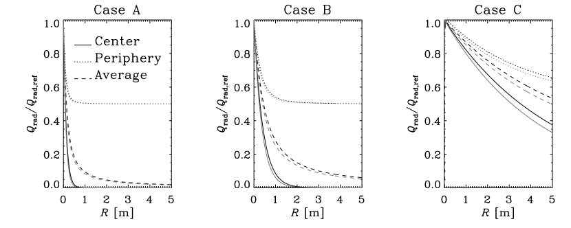
In Fig. 3 the radiative cooling of a particle normalized by the reference cooling given by Eq. (38) is plotted as a function of enclosure radius for different particle positions within the enclosure. The different position are 1) the center of the domain, given by Eq. (27) (solid line), 2) the periphery, given by Eq. (28) (dotted line) and 3) the position of the average particle, given by Eq. (37), (dashed line). It is clearly seen that the cooling is largest at the periphery, but that the difference is much less for case C where the particle number density is much smaller. Furthermore it is interesting to note that the average cooling approaches zero even for an enclosure radius of 5 m for case A and that the central particles of the same case experience near zero cooling even for enclosure radii less than a meter.
The grey lines in Fig. 3 represent a distribution width of while the black lines represent . As can be seen, the radiation term is not very sensitive to the width of the particle size distribution even for a width as wide as 20% of the mean particle radius. The effect of the broader particle size distribution is largest for small optical depths, as in Case C, but even here it is rather small.
Simulations of the gasification process presented in a paper by Qiao et al. (2012) qiao12 has been performed in order to emphasize the importance of including inter-particle radiation for dense clouds of particles. The numerical code used to perform the simulations was comparable to the code used in the above mentioned paper. Tests were done both with the same radiative cooling term as used by Qiao et al. (Eq. (38)), which neglects inter-particle radiation, and with the particle cooling term as proposed in this work (Eq. (37)), which includes inter-particle radiation. Compared to when inter-particle radiation is included, as given by Eq. (37), the time required to reach full conversion of the char is 47% longer when inter-particle radiation is neglected (Eq. (38)).
Analytical expressions for geometries of the confinement walls other than the spherical geometry considered in this work do not exist. It can be shownField67 , however, that other geometries like cylinders or cubes give trends for the heat transfer that are similar to what is found for spherical geometries. In particular it can be shown by numerical integration Field67 ; erkku that for cubes and cylinders having aspect ratios near unity, the expressions developed for spherical geometries give comparable results for the net heat transfer to the enclosure walls. It is therefore assumed to be a good approximation to use the expressions developed here also for real applications such as furnaces.
6 Conclusion
The particle cooling due to radiation has been investigated in particle clusters of variable size. When neglecting the effect of scattering and assuming all particles to behave alike it is shown that the radiative particle cooling is very sensitive to where the particle is positioned within the particle cluster. Broadening the particle size distribution is found to just have a minor impact on the results presented.
Instead of the traditional particle cooling term often used for single particle simulations of particles in a cluster of particles (Eq. (38)) a new particle cooling term is proposed (Eq. (37)) where the particle cooling is defined as the average particle cooling of all the particles. In contrast to Eq. (38), the new particle cooling term does include inter-particle radiation, which is found to be very important for the applications studied.
We claim that, compared to previous methods that neglect the inter-particle radiation, the use of the proposed radiative cooling term better approximates the radiative loss of a particle in a cloud of particles. The proposed method is applicable for simulations of small sub-volumes of gasifiers, pulverized coal combustors or any system where hot particle clouds exists. It is particularly useful when one is not interested in simulating the radiation from the full particle cloud but instead want focus on a single particle that represent all the other particles in the sub volume. Examples of such simulations are found in Qiao et al. qiao12 and Mitchell et al. mitchell07 .
Acknowledgements
This work forms part of the CAMPS project supported by the Research Council of Norway (215707). The work has additionally been produced with support from the BIGCCS Centre, performed under the Norwegian research program Centres for Environment-friendly Energy Research (FME). The authors acknowledge the following partners for their contributions: Aker Solutions, ConocoPhillips, Gassco, Shell, Statoil, TOTAL, GDF SUEZ and the Research Council of Norway (193816/S60).
References
- (1) Azad, F. H. and Modest, M. F., Int. J. Heat and Mass Transfer 24, 1681 (1981).
- (2) Park, J. H., Baek, S. W. and Kwon, S. J., Numerical Heat Transfer, Part A 33, 701 (1998).
- (3) Boutoub, A., Ettouati, H. and Benticha, H., Heat Mass Transfer 43, 613 (2007).
- (4) Qiao, L., Xu, J., Sane, A. and Gore, J., Combustion and Flame 159, 1693 (2012).
- (5) Xu, J. and Qiao, L. , Energy Fuels 26, 5759 (2012).
- (6) Mitchell, R. E., Ma, L. and Kim, B. , Combustion and Flame 151, 426 (2007).
- (7) Liu, X. J., Zhang, W. R. and Park, T. J., Combustion theory and Modeling 5, 595 (2001).
- (8) Booth, F., Pros. Phys. Soc. A 62, 95 (1949).
- (9) Park, S. , Kim, H. A., Ryu, C. , Yang, W., Kim, Y. J. and Seo, S., Journal of Mechanical Science and Technology 26, 1633 (2012).
- (10) Field, M. A., Gill, D. W., Morgan, B. B. and Hawksley, P. G. W., Combustion of pulverized coal. The British coal utilization research association, Surrey, England (1967).
- (11) Erkku, H., D. Sc. Thesis in chemical engineering MIT (1959)