Mitigation of the spectral dependent polarization angle response for achromatic half-wave plate
Abstract
Polarimetry using a half-wave plate (HWP) modulator provides the strong tools to avoid a detector noise and instrument-originated spurious polarization systematic effects. While the Pancharatnam achromatic HWP (AHWP) is commonly used for an application that needs a broadband frequency coverage, this technique introduces a frequency-dependent polarization angle rotation. In this paper we propose a new technique to mitigate this effect by introducing a second set of an AHWP. One rotational and one stationary set of AHWPs achieve a broadband coverage of modulation efficiency without the frequency-dependent polarization angle rotation. We conducted measurements by using three layers of sapphire wave plates and demonstrated this technique at millimeter wavelengths between 72 and 162 GHz. We also discuss a potential application in the CMB polarization experiment based on numerical simulations.
I Introduction
Measurements of the cosmic microwave background radiation (CMB) have been playing an important role to establish the CDM cosmology. While vast amount of information is learned by the Planck satellite using the temperature anisotropy of the CMB planck , there is a community-wide effort to measure the polarization of CMB to test the inflationary paradigm and to probe the evolution of the universe via interactions between the CMB and gravitational potential from the large scale structures Kamionkowski . These paradigms started to be disclosed by the recent results from the CMB polarization experiments, BICEP2, POLARBEAR, and SPTpol bicep2 ; polarbear_BB ; sptpol .
Forthcoming CMB polarization experiments require a polarimeter that is free from a detector noise and controls the instrument-originated polarization systematic effects. A polarimeter using a half-wave plate (HWP) modulator provides two attractive features, i) avoiding the detector by modulating and demodulating the signal frequency, and ii) eliminating the detector differencing, which is a source of the instrumentally induced spurious polarization effect, to reconstruct the incident polarization state hhz . MAXIPOL was the first CMB experiment that employed the continuously rotating HWP. Currently a number of CMB experiments, including ABS, EBEX, LiteBIRD, POLARBEAR-1, POLARBEAR-2, QUBIC, SPIDER, SWIPE are pursuing this technology maxipol ; brad_thesis ; abs ; ebex ; litebird ; polarbear1 ; polarbear2 ; qubic ; spider ; swipe .
While the use of HWP becomes a popular polarimetry technique, a polarimetry using a single HWP limits the use of the electromagnetic frequency range, and thus the observing detection bandwidth. The typical available bandwidth with a single HWP is in order to maintain the linear-to-linear polarization conversion efficiency to be more than 0.9. Upcoming CMB polarization experiments tend to cover the frequency range of or even broader in order to monitor the Galactic foreground (e.g. synchrotron and dust) emissions. Achromatic HWP (AHWP) is introduced by Pancharatnam pancharatnam and is employed by EBEX, the balloon-borne CMB experiment ebex ; matsumura_ahwp . The stack of the multiple plates with properly chosen offset angles achieves the retardance of broader than . While this is a very attractive option, one complication with the Pancharatnam AHWP is that the amount of angle rotated by the AHWP becomes an electromagnetic frequency dependence. This effect can be rephrased as the polarization sensitivity axis depends on the instrument bandpass shape and the source spectrum. When the two or more sources are mixed, the uncertainty of the polarization sensitive angle is not only depending on the spectral shapes but also the relative polarized intensities.
In this paper, we introduce the idea to mitigate the spectral dependence of the polarization angle. In section 2, we briefly review the AHWP polarimetery and introduce the mitigation recipe. In section 3, we show the experimental results as a demonstration of the idea. Finally in section 4 we discuss the actual implementations for forthcoming CMB experiments.
II Mitigation recipe
II.1 AHWP polarimetry
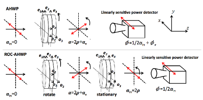
The detailed descriptions of the AHWP polarimetry and its formalism can be found in Matsumura et al. matsumura_ahwp . Here we briefly review the AHWP polarimetry. Figure 1 shows the configurations of the polarimeter we assume throughout this paper.
The expected signal can be formulated by using the Mueller matrix as below
| (1) |
where is the Stokes vector of the incident linearly polarized signal. In this paper, we assume
| (2) | |||||
| (3) |
where is the incident intensity, is the incident degree of polarization, is the incident polarization angle with respect to the detector polarization sensitivity axis, the -axis. The output Stokes vector is . The Mueller matrices, , , are for a retarder, rotation and wire grid. The detailed matrix elements are shown in Appendix. The angle is the offset wave plate angle about the -axis for an plate with respect to the -axis, see Figure 1. The total number of wave plates that consist of one set of AHWP is . The angle is the wave plate angle. The retardance is
| (4) |
where is the speed of light, and and are the ordinary and extra-ordinary indices of the refraction of the wave plate, respectively. As a part of the construction parameters, we determine the thickness of the HWP, , as
| (5) |
where is the central frequency of the detection band.
Without taking into account the effect of reflection from a wave plate, the intensity as a function of a wave plate angle (intensity vs angle = IVA), , for a single HWP can be analytically expressed as
| (6) | |||||
where is modulation efficiency defined as
| (7) |
We also define the phase of IVA and relate to the incident polarization angle as
| (8) |
When we apply Equation (6) to the IVA of AHWP, we introduce an extra phase, , as
| (9) |
in order to take into account the phase variation as a function of frequency, and thus the phase of the modulation is expressed as
| (10) |
The extra term, , has a spectral dependence, i.e. the spectra of a source and instrument. Thus, a polarimeter using AHWP has the intrinsic source of uncertainty in its polarization angle unless one knows the source spectrum to the required precision. The quantitative discussion about this effect in the context of a CMB polarization experiment can be found in Matsumura et al. and Bao et al.matsumura_ahwp ; bao .
II.2 Introducing the rotational-offset-canceling AHWP
The idea to mitigate the frequency dependence of the polarization angle with the use of rotating AHWP is to place a second set of the AHWP that is moving with respect to the first set of the AHWP. The simplest configuration for the second set is to prepare an identical stationary AHWP as shown in the bottom of Figure 1.
The first set is placed to modulate the incident polarization angle. The second set still maintains the high modulation efficiency and also rotate the offset of the incident polarization angle back. Hereafter, we call this configuration the rotational-offset-canceling AHWP (ROC-AHWP). The above configuration can be written down by using the Mueller matrices as
| (11) | |||||
The detected intensity is the first element of the output Stokes vector. The rotational angles of the two AHWPs, and , need to be not identical. The simplest configuration is to set and let to rotate. We reconstruct the phase, , from IVA and this now does not have the spectral dependence while maintaining high modulation efficiency, .
III Measurements
We conducted an experiment to demonstrate the concept of the ROC-AHWP.
III.1 Sample preparation
We prepare the 50 mm diameter of an A-cut single crystal sapphire as a wave plate. We construct the two sets of the stacked three wave plates () with the offset angles of (0, 55, 0) degrees. The relative offset angles between the wave plates are aligned within 0.5 degrees. The thickness of each sapphire sample is mm. The ordinary and extra-ordinary indices of the sapphire at the room temperature are assumed to be 3.07 and 3.40 brad_thesis . The surfaces of the first and the third sapphire layers are anti-reflection (AR) coated with two layers of dielectric materials. The first AR layer on the sapphire is Stycast2850FT with a thickness of mm and the second layer on Stycast2850FT is the teflon sheet with a thickness of mm. We apply this two-layer AR coating only to the sapphire surface that faces to the air and did not apply the interface layer between the two sapphires. The three layers of sapphire are held mechanically.
III.2 Experimental setup
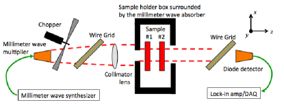
Figure 2 shows the experimental setup to measure the modulation efficiency and the phase of IVA. We use the millimeter-wave generator and the (W-band) and (D-band) multipliers as millimeter wave sources to produce the spectral range between 72 and 162 GHz. The source is linearly polarized and we also use two free-standing wire-grid polarizers to define the polarized orientation. We define the incident polarization angle of degrees as the polarization vector referenced with respect to the -axis. The linearly polarized signal is measured by a diode detector that is sensitive to linearly polarized light. The signal is chopped at 13 Hz and the detected modulated signal is demodulated by the lock-in amplifier and read by data acquisition system.
The incident beam from the source is collimated by a spherical lens made by Rexolite and the beam is further collimated by the 2.5 cm diameter aperture. The AHWP (sample #1) is located on the automated rotatable mount and the stationary AHWP (sample #2) is placed after the rotating AHWP. The first AHWP rotated over 360 degrees with a step of 10 degrees at the given electromagnetic frequency and we extract the modulation efficiency and phase from the IVA. We repeat this measurement over the frequency range from 72 to 108 GHz using the W-band source and detector, and from 117 to 162 GHz using the D-band source and detector.
The AHWP is mounted on a sample holder. The rotational position of the sample holder is aligned with respect to the -axis within 5 degrees. We calibrate the global offset angle about the -axis between the sample and the -axis by using the wire grid.
IV Results
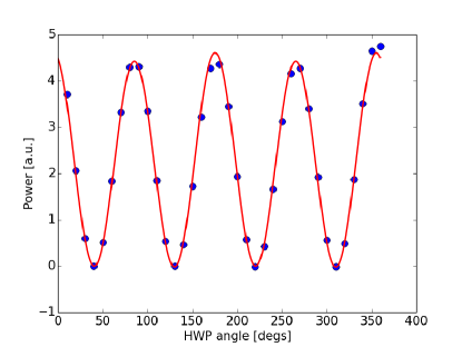
Figure 3 shows the typical IVA data. The IVA is fitted with the following model,
| (12) |
We define the normalized modulation efficiency, , and the phase, , of the IVA as
| (13) |
The normalized efficiency for a single HWP can be analytically solved as
| (14) |
We use the normalized modulation efficiency instead of the modulation deficiency defined in Equation (7). This is because the source intensity, , is not well known over the spectral range while we can ensure to achieve by using the combination of the linearly polarized source and the wire grid.
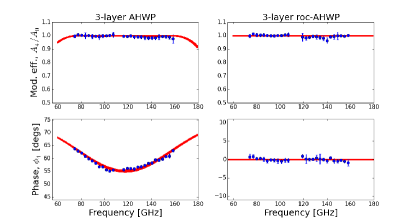
Figure 4 shows the modulation efficiency and the phase as a function of the electromagnetic frequency for the AHWP and the ROC-AHWP. The phase of the AHWP shows the spectral dependence. On the other hand, the phase of the ROC-AHWP has a flat response. The modulation efficiency of AHWP and ROC-AHWP is close to 1 over broadband, .
The error on each data point in Figure 3 and 4 is estimated by three noise sources, statistical noise, thermal drift, and standing wave in the system due to the non-perfect AR coating. The fractional statistical error is less than over 1 sec of the integration time and the temperature of the source is stationary within 0.1 degrees. The thermal drift is estimated by repeating the measurements multiple times over a few hour separations. The systematic error due to the reflection is estimated by the deviation of IVA from Equation (12).
The red lines are the predicted curves without taken into account the effect of reflection from the wave plate surfaces. The predicted curves have thickness due to the uncertainties in the thickness of each wave plate and the offset angles between the wave plates. The data points and the predicted curves are well agreed within 1- error bar.
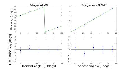
Figure 5 shows the phase as a function of the incident polarization angle. The phase at each incident angle is averaged between 72 and 108 GHz. The error bar on each data point is dominated by the uncertainty of the incident polarization angle. The uncertainty of the wire grid orientation is degrees and this is limited by the tick mark of the wire grid holder. This error is propagated to the error on the phase.
| Experiment | # of plates | [mm] ( [GHz]) | Band [GHz] | Bandwidth [%] | HWP offset angles [degs] |
|---|---|---|---|---|---|
| POLARBEAR-2 | 3 | 3.74 (126.6) | 95, 150 | 30 | (0, 56, 0) |
| LiteBIRD | 9 | 2.52 (187.5) | 60, 78, 100 | 23 | (0, 18.5, 217.5, 73.9, 141.5, |
| 140, 195, 280 | 30 | 73.9, 217.5, 18.5, 202.7) |
V Discussions
We discuss the detailed feature that may become the potential systematic effect with the use of ROC-AHWP. We also discuss the design parameters for two upcoming CMB experiments that potentially use the AHWP base polarimetry.
V.1 Incident angle dependent modulation efficiency
When one designs the AHWP, there is a tradeoff between the high modulation efficiency and the bandwidth by tuning the offset angles. In one application, if one does not necessary need the modulation efficiency of 1 in the detection bandwidth, one can gain wider bandwidth with modulation efficiency less than 1.
As for the ROC-AHWP design, one needs a careful treatment in this tradeoff. When the retardance is not equal to after the first set of the AHWP, a partial circularly polarized light is incident to the second AHWP. In such a case, the outgoing light is further circularly polarized. Therefore, the second AHWP enhances to the lower modulation efficiency.
If the retardance is , the polarized light after the first AHWP gains some amount of . This non-zero polarized light incidents to the second AHWP with some polarization angle with respect to the axis of the second AHWP. In such a case, the degradation of the modulation efficiency depends on what the initial polarization angle is with respect to the first AHWP. If one designs the ROC-AHWP for an application that needs no incident angle dependence in the modulation efficiency, one has to carefully choose the construction parameters in order to maximize the modulation efficiency for all the incident polarization angles with some sacrifice of the bandwidth.
V.2 ROC-AHWP design for POLARBEAR-2 and LiteBIRD
We describe the candidate ROC-AHWP design for upcoming CMB polarization experiments, POLARBEAR-2 and LiteBIRD. Our design assumes the design parameters described in Table 1. We optimize the offset angles in such that the modulation efficiency is as close as and the flatness of the phase over the detection bands.
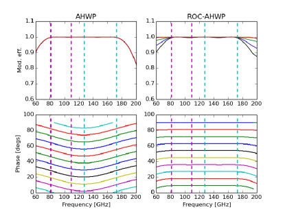
Figure 6 shows that the modulation efficiency and the phase of the AHWP and ROC-AHWP for POLARBEAR-2. The band averaged modulation efficiencies for 95 and 150 GHz (with 30% bandwidth) of the ROC-AHWP design are and , respectively, for all the incident polarization angles. The RMS variations of the phase within the detection bandwidth of 95 and 150 GHz are less than 0.05 degrees.
The effect, which is previously discussed as the incident angle dependent modulation efficiency, is particularly evident below 80 GHz and above 173 GHz of the ROC-AHWP. Some amount of this effect is also present within the detection band indicated as dashed lines. The impact of these values to a CMB polarization experiment is beyond the scope of this paper, and it requires the end-to-end simulation to assess the impact of this performance. When the requirement is stringent, the potential solution to improve the performance is to add more plates to widen the bandwidth with higher modulation efficiency.
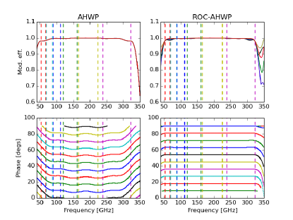
Figure 7 shows the modulation efficiency and the phase of the AHWP and ROC-AHWP for LiteBIRD. It consists of the 9 stacked sapphire plates. The offset angles for the 9 plates are chosen by conducting the Monte Carlo simulation and maximizing the modulation efficiency over GHz. This is one of the candidate offset angles that cover the detection bandwidth of LiteBIRD. Table 2 shows the band averaged modulation efficiency and the RMS fluctuation of the phase within the band.
| Band [GHz] | [degs] | |
|---|---|---|
| 60 | ||
| 78 | ||
| 100 | ||
| 140 | ||
| 195 | ||
| 280 |
V.3 Implementations
This ROC-AHWP inevitably doubles the total thickness of the AHWP in the optical path and the surface that potentially reflects the incident radiation. In the application that needs high transmittance, one has to choose a low-loss birefringent material and proper anti-reflection coating in the required bandwidth.
When the two parallel optical elements are placed like the ROC-AHWP, the standing wave may cause undesired fringe pattern in the spectrum of the detection band. The simplest solution is to apply a proper AR coating. As a result, the requirement to the broadband AR coating may become more demanding with the ROC-AHWP.
The modulation efficiency and phase response at around and behave the same regardless of the order of the first AHWP being rotating and the second set being stationary, or vice versa. One can choose the configuration that fits better to the optical system. This feature can be considered as redundancy in a system requiring a polarimeter on balloon-borne and satellite missions. Generally the rotation of the polarimeter is one of the key features to maintain the measurements and the failure of the rotation can be fatal. The second stationary AHWP can hold the rotational mechanism that is nominally not activated and the extra-mechanism can be activated when there is a failure in the rotation of the first AHWP.
In millimeter wave applications, sapphire is one of the typical birefringent materials due to the large differential indices between the ordinary and extra-ordinary axes. Sapphire is known as a high thermal conductive material (1 W cm-1K-1 between 4 and 100 K) pobell . Therefore, the stationary sapphire with a proper AR coating can serve not only as a part of the second set of the AHWP in the ROC-AHWP but also serve as a thermal filter that absorbs infrared radiation at cryogenic temperature. For this use, the correct choice of the AR coating material with features, absorptive at IR and transparent in millimeter wave (such as a thin layer of Stycast), should achieve a functionality as a thermal filter. The similar concept is proposed using alumina with the Stycast AR coatings as an IR filter at the cryogenic temperature alumina_filter .
In a HWP based polarimetry using a continuous rotation, another possible operational mode is to rotate the two AHWPs of the ROC-AHWP in opposite directions. In Equation (11), one can set and , where is the angular velocity of the AHWP and is time. In this mode, the total angular momentum of the ROC-AHWP can be canceled. When the angular momentum due to the rotation of the AHWP can be a source of disturbance in a system, such as a satellite or balloon payload attitude control system, one can achieve the continuously rotating HWP based polarimetry with zero-momentum. In this case, one should aware that the polarization signal appears at instead of , i.e. the nominal frequency that the polarization signal appears with a single AHWP. Therefore, this double spinning ROC-AHWP in the opposite directions can add an extra feature of increasing the signal band. This is a particularly interesting option when a physical rotational frequency of the AHWP is limited.
While we demonstrated this concept of the ROC-AHWP at millimeter wavelengths experimentally, the principle of the ROC-AHWP can be applicable to any wavelengths. Thus, this ROC-AHWP can be a viable candidate technology for any applications that use broadband polarimetry, including solar physics, expoplanet search, aerosol characterization, and biomedical applications.
VI Conclusions
We introduced the recipe to mitigate the spectral dependent phase response of the AHWP polarimeter by introducing the second set of the AHWP that rotates or is stationary with respect to the first set of the AHWP. We experimentally show that the ROC-AHWP configuration with achieves degrees while the phase of a single set of AHWP varies degrees between 72 and 162 GHz. We also computationally show the potential ROC-AHWP design for POLARBEAR2 with and for LiteBIRD with . Although we demonstrate this ROC-AHWP at the millimeter wavelength, the ROC-AHWP concept is applicable to any broadband polarimeter application.
Acknowledgement
We would like to thank to Masashi Hazumi for useful discussions. This work was supported by MEXT KAKENHI (Grant Nos. 24740182 and 24111715).
Appendix
Elements of Mueller matrix
The elements of the Mueller matrix that are used in this paper are listed below.
| (15) | |||||
| (16) | |||||
| (17) |
For more general expression, please see Appendix in Shurcliff shurcliff .
References
- (1) Planck Collaboration,“Planck 2013 results. I. Overview of products and scientific results,” Astronomy & Astrophysics manuscript no. Planck Mission 2013.
- (2) Kamionkowski M and Kosowsky A 1999 Ann. Rev. Nucl. Part. Sci. 49 77.
- (3) BICEP2 collaboration, “BICEP2 I: Detection Of B-mode Polarization at Degree Angular Scales,” arXiv:1403.3985.
- (4) POLARBEAR collaboration, “A Measurement of the Cosmic Microwave Background B-Mode Polarization Power Spectrum at Sub-Degree Scales with POLARBEAR”, arXiv:1403.2369.
- (5) D. Hanson et al. (SPTpol Collaboration), “Detection of B-Mode Polarization in the Cosmic Microwave Background with Data from the South Pole Telescope,” Phys. Rev. Lett. 111, 141301, 30 September 2013.
- (6) W. Hu, M. Hedman, M. Zaldarriaga, “Benchmark Parameters for CMB Polarization Experiments,” Phys.Rev.D67:043004,2003
- (7) Wu et al., “MAXIPOL: Data Analysis and Results”, The Astrophysical Journal, 665:55-66, 2007 August 10
- (8) B. R. Johnson, “MAXIPOL: a bolometric, balloon-borne experiment for measuring the polarization anisotropy of the cosmic microwave background radiation,” Ph.D. dissertation (University of Minnesota, Twin Cities, Minneapolis, 2004).
- (9) A. Kusaka et al., “Modulation of CMB polarization with a warm rapidly-rotating half-wave plate on the Atacama B-Mode Search (ABS) instrument”, Rev. Sci. Instrum., 85, 024501 (2014).
- (10) B. Reichborn-Kjennerud et al., “EBEX: a balloon-borne CMB polarization experiment”, Proc. SPIE 7741, Millimeter, Submillimeter, and Far-Infrared Detectors and Instrumentation for Astronomy V, 77411C (July 15, 2010); doi:10.1117/12.857138.
- (11) T. Matsumura et al., “Mission design of LiteBIRD”, Journal of Low Temperature Physics, February 2014.
- (12) H. Nishino et al., “POLARBEAR CMB Polarization Experiment”, Proceedings of the 12th Asia Pacific Physics Conference JPS Conf. Proc. 1, 013107 (2014).
- (13) T. Matsumura et al., “Cosmic Microwave Background B-mode Polarization Experiment POLARBEAR-2,” Proceedings of the 12th Asia Pacific Physics Conference JPS Conf. Proc. 1, 013108 (2014).
- (14) A. Ghribi et al., “Latest Progress on the QUBIC Instrument”, Journal of Low Temperature Physics, February 2014.
- (15) S. Bryan et al., “Modeling and characterization of the SPIDER half-wave plate”, Proc. SPIE 7741, Millimeter, Submillimeter, and Far-Infrared Detectors and Instrumentation for Astronomy V, 77412B (15 July 2010).
- (16) P. de Bernardis et al., “SWIPE: a bolometric polarimeter for the Large-Scale Polarization Explorer”, Proceedings of the SPIE Astronomical Telescopes + Instrumentation 2012 Conference - Millimeter, Submillimeter, and Far-Infrared Detectors and Instrumentation for Astronomy VI - Amsterdam 1-6 July 2012, paper #8452-125.
- (17) S. Pancharatnam, “Achromatic combinations of birefringent plates,” Proc. Ind. Acad. Sci. 41, 137-144 (1955).
- (18) T. Matsumura et al., “Performance of three- and five-stack achromatic half-wave plates at millimeter wavelengths”, Applied Optics, Vol. 48 Issue 19, pp.3614-3625 (2009).
- (19) C. Bao et al., “The Impact of the Spectral Response of an Achromatic Half-Wave Plate on the Measurement of the Cosmic Microwave Background Polarization”, Astrophys.J. 747 (2012) 97.
- (20) F. Pobell, ”Matter and Methods at Low Temperatures”, Springer (2007).
- (21) Y. Inoue, T. Matsumura et al., “Cryogenic infrared filter made of alumina for use at millimeter wavelength,” Applied Optics, Vol. 53, No. 9, 20 March 2014.
- (22) W. Shurcliff, “Polarized light”, Oxford University Press, 1962.