Large Tunneling Anisotropic Magneto-Seebeck Effect in a CoPtMgOPt Tunnel Junction
Abstract
We theoretically investigate the Tunneling Anisotropic Magneto-Seebeck effect in a realistically-modeled CoPtMgOPt tunnel junction using coherent transport calculations. For comparison we study the tunneling magneto-Seebeck effect in CoPtMgOCoPt as well. We find that the magneto-Seebeck ratio of CoPtMgOPt exceeds that of CoPtMgOCoPt for small barrier thicknesses, reaching at room temperature. This result provides a sharp contrast to the magnetoresistance, which behaves oppositely for all barrier thicknesses and differs by one order of magnitude between devices. Here the magnetoresistance results from differences in transmission brought upon by changing the tunnel junction’s magnetization configuration. The magneto-Seebeck effect results from variations in asymmetry of the energy-dependent transmission instead. We report that this difference in origin allows for CoPtMgOPt to possess strong thermal magnetic-transport anisotropy.
Due to their presence in hard-disk drives and growing potential as commercially viable memory bits, magnetic tunnel junctions (MTJs) continue to provide impetus for scientific study. The demand for smaller devices and efficient energy consumption mandates further investigation of their thermal properties. Such considerations recently prompted a renewed interest in the long-known Seebeck effect, in which a temperature gradient spanning a material induces a voltage. The discovery of corresponding thermal effects in spin-polarized systems heralded a new field of research known as Spin Caloritronics BauerSpinCaloritronics . In one such effect the (charge) Seebeck Coefficient changes as a function of a device’s magnetization configuration - known as the magneto-Seebeck effect or magnetothermopower - in analogy with the magnetoresistance. Recently observed experimentally WalterMagnetoSeebeck ; LiebingMagnetothermopower ; NaydenovaThermopower ; TMSExperiment1 ; TMSExperiment2 ; TAMSExperiment1 ; TAMSExperiment2 and studied theoretically MagnetoSeebeckTheoryAbInitio1 ; MagnetoSeebeckTheoryAbInitio2 ; MagnetoSeebeckTheoryBoltzmann2 , the magneto-Seebeck effect enables one to tune the thermal properties of an MTJ via magnetic field, potentially enabling thermal spin-logic or assisting in the recycling of wasted heat. We numerically study two devices: CoPtMgOPt (which we call an anisotropic MTJ) and CoPtMgOCoPt (a normal MTJ). Although the magnetoresistance ratios of both devices differ by one order of magnitude, we find that their magneto-Seebeck ratios are comparable. Furthermore, the anisotropic MTJ (or AMTJ for short) produces magneto-Seebeck ratios exceeding those of the normal MTJ at small barrier widths (shown in Figs. 1 and 6), peaking at values of at K and at K.
Throughout this work we use the following ratios
| Magnetoresistance (MR) Ratio | (1) | |||
| Magneto-Seebeck (MS) Ratio | (2) |
to quantify the strengths of the aforementioned effects in both devices. The numerators denote the greatest difference in conductance () or Seebeck coefficient () between any two magnetization directions. The denominators represent the maximum absolute value of either quantity, yielding the so-called pessimistic ratio. We use these ratios to provide a consistent comparison between effects, and to avoid artificially high magneto-Seebeck ratios brought upon by vanishing Seebeck coefficients.
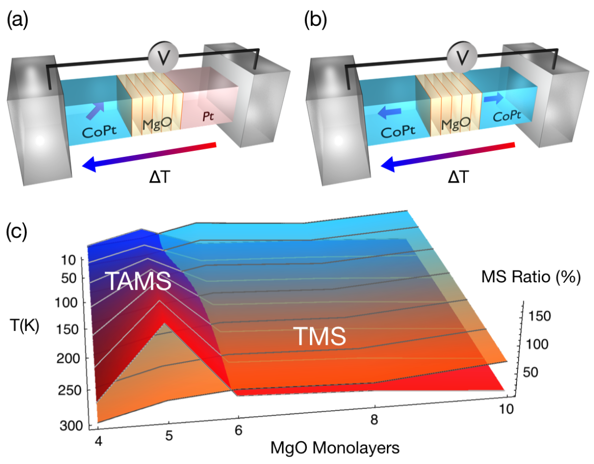
In regards to CoPtMgOCoPt, which exhibits the Tunneling Magnetoresistance (TMR) effect, we study the perpendicular-to-plane [001] parallel and antiparallel magnetization configurations. On the other hand, CoPtMgOPt exhibits the Tunneling Anisotropic Magnetoresistance (TAMR) effect; for this system we rotate the free layer’s magnetization from perpendicular-to-plane [001] to in-plane [100] over seven steps. In analogy with the TMR and TAMR effects, the normal MTJ exhibits the Tunneling Magneto-Seebeck (TMS) effect while the anisotropic MTJ exhibits the Tunneling Anisotropic Magneto-Seebeck (TAMS) effect.
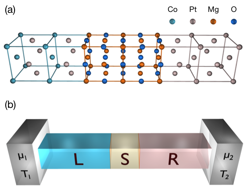
We model each material system as a two-terminal device, consisting of a scattering center (MgO) and two semi-infinite leads (CoPt or Pt). Our CoPt electrode consist of alternating monolayers of Co and Pt, ending with a Pt monolayer at the interface (Fig. 2a). We subdivide the leads into principal layers, each consisting of two monolayers, so that our Hamiltonian retains a block-tridiagonal structure in the presence of next-nearest neighbor interactions. The unit cell of each principal layer repeats periodically in-plane (perpendicular to transport), establishing a two-dimensional Brillouin Zone (2DBZ) per layer. We assume that the corresponding wavevectors furnish good quantum numbers across the interfaces, enabling a common 2DBZ across each device. To simulate a finite cross-sectional area, we enforce phase-repeating boundary conditions over some area in real space, constraining the available states in -space to a minimum separation.
Our transport calculations utilize the Landauer-Büttiker formalism SivanImry1986 ; Buttiker , in which transmission is computed via Green’s Functions VelevButlerReview . We obtain all material Hamiltonians using the Slater-Koster tight-binding method SlaterKoster , with parameters fitted to reproduce ab-initio electronic structure calculations Zemen201487 ; TanDFT . Within the ferromagnetic leads we use Stoner parameters to simulate the magnetization of the Co and Pt monolayers, the latter of which are slightly magnetized by proximity to Co. We include spin-orbit coupling in all atoms to fully capture the magnetic transport-anisotropy. Furthermore, we simulate interfacial strain between the leads and the sample via perturbations of hopping parameters.
The Landauer-Büttiker formalism expresses transport in terms of transmission probabilities obtained from a multi-dimensional scattering problem SivanImry1986 ; Buttiker . The scattering modes are eigenstates parameterized by the complex band structure of each lead. For a given tunneling energy (E), transverse crystal momentum (), and out-of-plane magnetization direction () in the free CoPt lead, the transmission function is given by
| (3) |
| (4) |
where represents the Green’s function of the sample and gives the self-energy connecting a particular lead to the sample. The subscripts denote the (left/right) leads, while the superscripts label the kind of Green’s function (retarded/advanced) used to calculate that particular quantity.
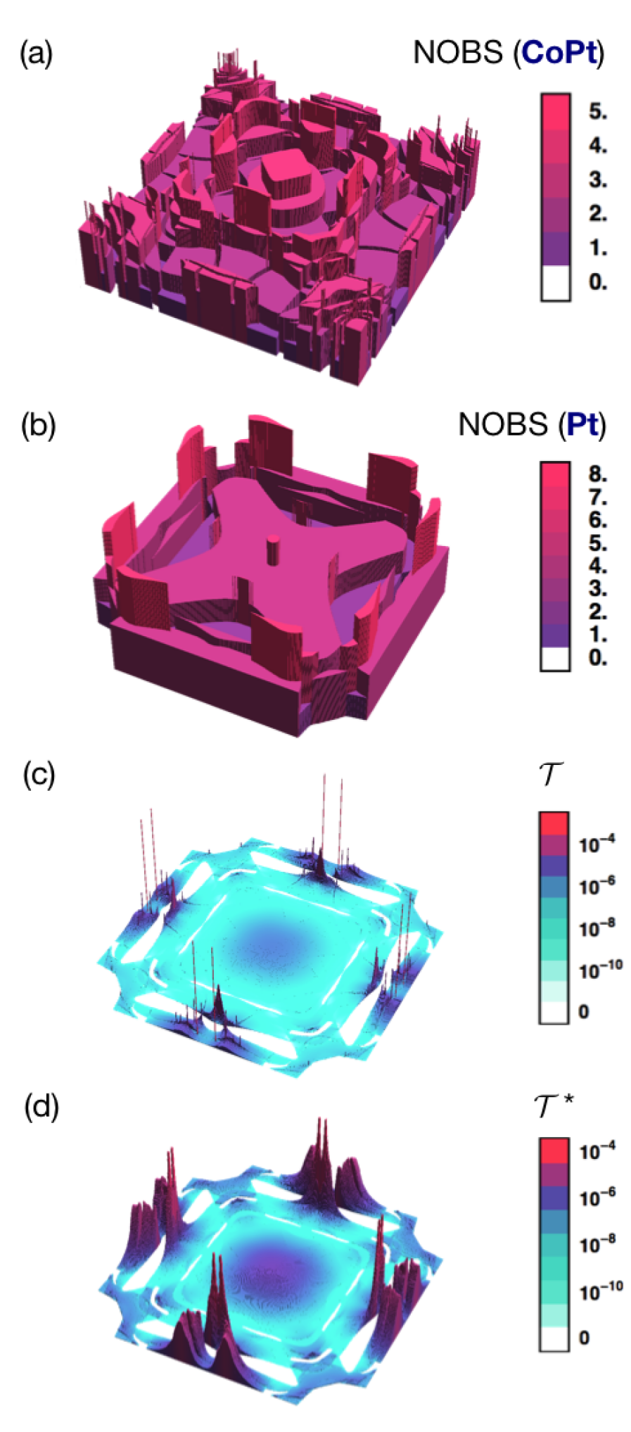
Figure 3c shows the transmission plotted over the 2DBZ for CoPtMgOPt with a five monolayer barrier thickness. Sharp peaks known as “hot spots” occur across the -dependent transmission. Theoretical studies of Fe-based MTJ’s with crystalline MgO tunnel barriers show that these hot spots contribute negligibly to the calculated magnetoresistance ratios ButlerDeltaStates . In these cases, majority carriers belonging to the so-called state dominate transport, overwhelming the contributions of hot spots found throughout the rest of the transmission.
Enforcing phase-repeating boundary conditions constrains one to a maximum number of points (due to their minimum-allowed separation). Our 2DBZ has an edge length of 1.2358 inverse Bohr radii; this implies that a cross-sectional area of 50 nm 50 nm allows for points while 200 nm 200 nm admits 552,049 points. Between 66,049 and 263,169 points we find a compromise. In this regime, converges better than 2% for both device structures and all magnetization directions, energies, and barrier widths – if all hot spots are removed. Following ZhangButlerRemoveHotSpots , we remove hot spots in regions that would only converge well past a cutoff in the number of points (which we establish through finite-size considerations).
The sum of transmission probabilities over the 2DBZ gives the energy-dependent transmission T:
| (5) |
To incorporate the effects of temperature, we populate available states with non-interacting electrons that obey Fermi-Dirac statistics, and neglect the contributions of inelastic phonons. We assume that differences in temperature and electrochemical potential between the leads produce first-order variations in the Fermi-Dirac distribution with respect to energy, and no deviations in the transmission function (the linear-response limit). In this approximation, we may express the conductance and Seebeck coefficient as
| (6) | ||||
| (7) |
respectively, where
| (8) |
is the energy-dependent transmission weighted by the derivative of the Fermi-Dirac distribution. Note that all temperature-dependent quantities explicitly depend on the chosen Fermi level .
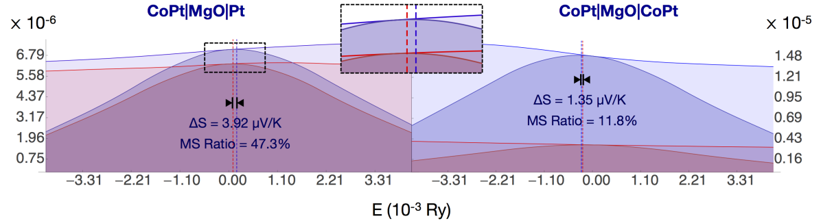
Eqs. 6 and 7 provide a simple theoretical explanation for the origins of the magnetoresistance and magneto-Seebeck effects. Whereas the conductance corresponds to the energy integral of G, the Seebeck coefficient corresponds to the geometric center of G with respect to the Fermi level. Thus, strong differences in the overall transmission, brought upon by rotating magnetization, lead to an appreciable magnetoresistance. However, variations in the asymmetry of the energy-dependent transmission yield the magneto-Seebeck effect.
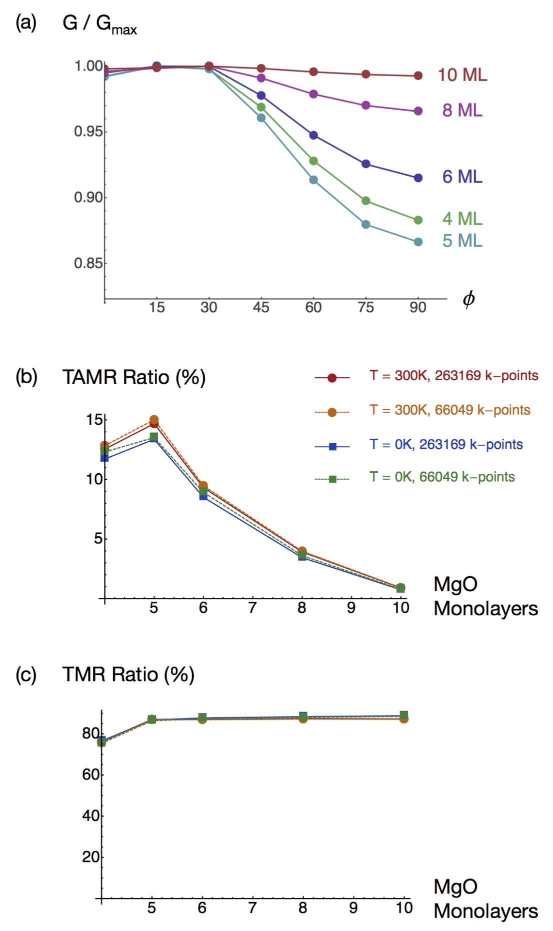
We now discuss our results, beginning with the magnetoresistance effect. Panel 5a displays normalized TAMR curves for various barrier thicknesses. For barrier thicknesses greater than five MgO monolayers, the percentage difference between the high and low conductance states diminishes. Panels 5b and 5c plot the simulated magnetoresistance ratios for various temperatures as a function of barrier thickness. In accordance with panel 5a, the TAMR ratio peaks at five MgO monlayers (17.2%) but decreases afterwards; however the TMR ratio saturates as barrier thickness increases (88.8% at ten MgO monolayers). In general the two devices produce magnetoresistance ratios roughly one order of magnitude apart.
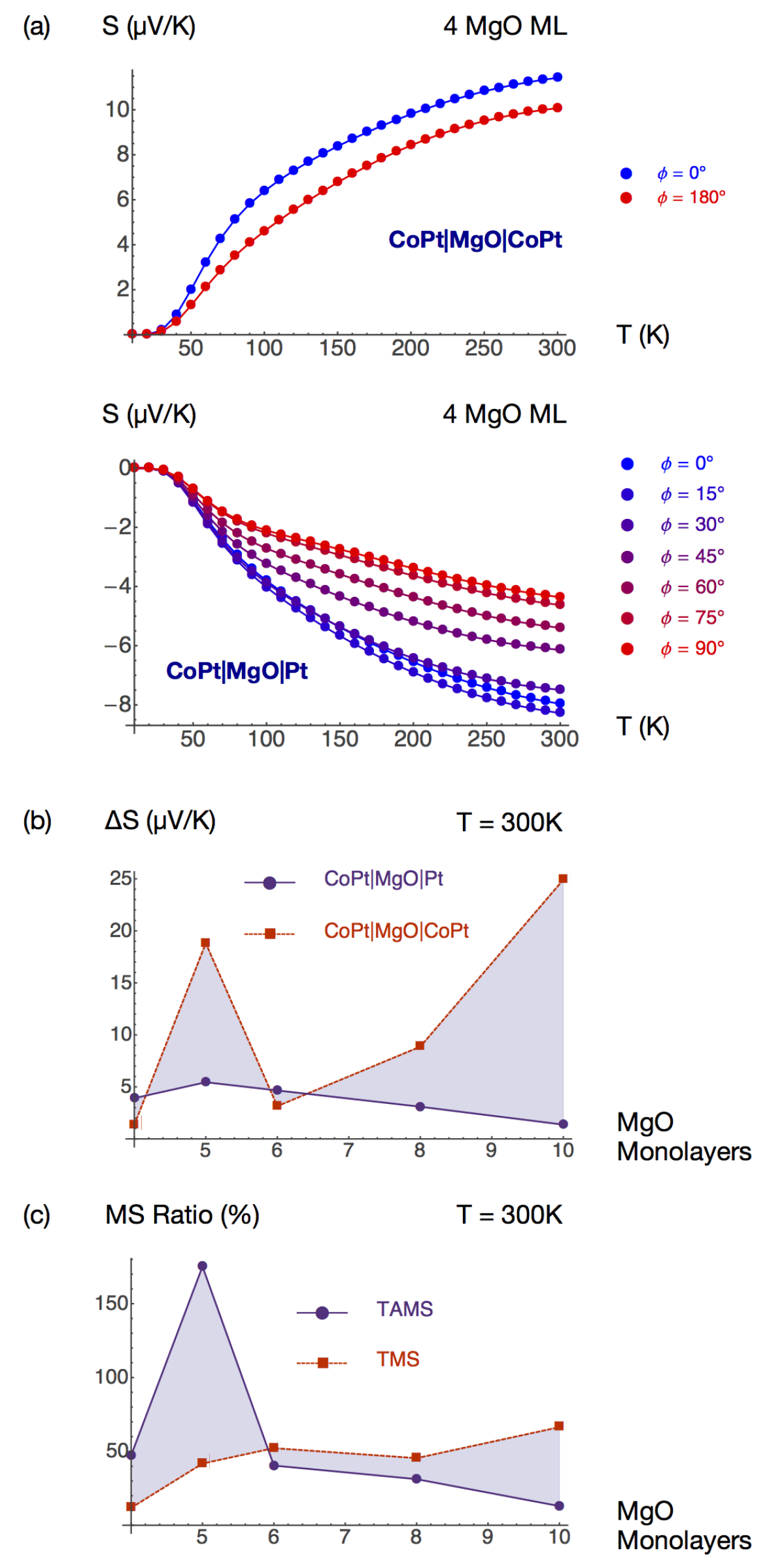
Moving now to the magneto-Seebeck effect, which encapsulates the main result of this letter, we direct the reader to Fig. 6. Panel 6a shows the Seebeck coefficients plotted versus temperature for both devices (four MgO monolayers) and all magnetizations. Here the normal and anisotropic MTJs yield Seebeck coefficients of similar strength. Beyond four MgO monolayers, both devices produce comparable differences in Seebeck coefficient (panel 6b) and magneto-Seebeck ratios (panel 6c). Furthermore, the magneto-Seebeck ratios of the anisotropic device surpass those of the normal device for lower barrier thicknesses, peaking at absolute values of at K and at K.
Unlike the conductance, the Seebeck coefficient may vanish, potentially causing the magneto-Seebeck ratio to diverge. In general, small absolute values of produce artificially high magneto-Seebeck ratios; thus both the difference in Seebeck coefficient () and the magneto-Seebeck ratio factor into a device’s performance. In our case, although the Seebeck coefficients of some magnetization configurations vanish, (corresponding to = 90 for the AMTJ and = 180 for the MTJ) never does.
In CoPtMgOPt, spin-polarized electrons leaving the ferromagnetic layer tunnel into a region with no spin preference; thus the single ferromagnetic layer alone controls the magnetic transport anisotropy (through spin-orbit coupling). However, in CoPtMgOCoPt, spins polarized by the first layer tunnel into a receiving layer with either strong (parallel configuration) or weak (antiparallel configuration) preference for their spin, providing a stronger spin-filter irrespective of spin-orbit coupling. Thus, anisotropic MTJs often yield lower magnetoresistance ratios than normal MTJs. Thermally-induced voltages appear to behave differently. The magneto-Seebeck effect stems from changes in the asymmetry of brought upon by rotating magnetization. In principle, such variations in asymmetry need not be connected to variations in the overall transmission. In agreement with this assumption, our results indicate that CoPtMgOPt possesses thermal transport anisotropy similar or better than CoPtMgOCoPt.
To conclude, we have demonstrated that magnetic tunnel junctions possessing a single ferromagnetic layer can produce magneto-Seebeck ratios exceeding those of normal MTJs. This behavior provides a sharp contrast to that of the magnetoresistance. We performed coherent transport calculations simulating the magnetoresistance and magneto-Seebeck effects in CoPtMgOCoPt and CoPtMgOPt magnetic tunnel junctions. The anisotropic MTJ yields magneto-Seebeck ratios comparable or better to those of the normal MTJ, reaching absolute values of at room temperature. Thus we find that exploiting spin-orbit coupling in MTJs with a single ferromagnetic contact can lead to enhanced magnetic-transport anisotropies.
Acknowledgements.
The authors gratefully acknowledge Jan Mašek for helpful discussions. This work was supported by the National Science Foundation through the Materials Research Science and Engineering Center at The Ohio State University (DMR-0820414), EPSRC grant no. EP/H029257/1, the EU European Research Council (ERC) advanced grant no. 268066, the Ministry of Education of the Czech Republic grant no. LM2011026, the Grant Agency of the Czech Republic grant no. 14-37427G, the Academy of Sciences of the Czech Republic Praemium Academiae, and the Alexander Von Humboldt Foundation.References
- [1] G. E. W. Bauer, E. Saitoh, and B. J. van Wees. Nature Materials, 11:391–399, May 2012.
- [2] A. Boehnke, M. Walter, N. Roschewsky, T. Eggebrecht, V. Drewello, K. Rott, M. Munzenberg, A. Thomas, and G. Reiss. Review of Scientific Instruments, 84(6):–, 2013.
- [3] T. Bohnert, V. Vega, A-K Michel, V. M. Prida, and K. Nielsch. Applied Physics Letters, 103(9):–, 2013.
- [4] W. H. Butler, X.-G. Zhang, T. C. Schulthess, and J. M. MacLaren. Phys. Rev. B, 63:054416, Jan 2001.
- [5] M. Buttiker. Phys. Rev. B, 46:12485–12507, Nov 1992.
- [6] M Czerner and C Heiliger. Journal of Applied Physics, 111(7), 2012.
- [7] C Heiliger, C Franz, and M Czerner. Phys. Rev. B, 87:224412, Jun 2013.
- [8] N. Liebing, S. Serrano-Guisan, K. Rott, G. Reiss, J. Langer, B. Ocker, and H. W. Schumacher. Phys. Rev. Lett., 107:177201, Oct 2011.
- [9] C Lopez-Mon s, A Matos-Abiague, and J Fabian. arXiv:1309.3463, 2013.
- [10] M. Magnuson, M. Mattesini, N. V. Nong, P. Eklund, and L. Hultman. Phys. Rev. B, 85:195134, May 2012.
- [11] Ts. Naydenova, P. Dürrenfeld, K. Tavakoli, N. Pégard, L. Ebel, K. Pappert, K. Brunner, C. Gould, and L. W. Molenkamp. Phys. Rev. Lett., 107:197201, Oct 2011.
- [12] U. Sivan and Y. Imry. Phys. Rev. B, 33:551–558, Jan 1986.
- [13] J. C. Slater and G. F. Koster. Phys. Rev., 94:1498–1524, Jun 1954.
- [14] Y. Tan, M. Povolotskyi, T. Kubis, Y. He, Z. Jiang, G. Klimeck, and T. B. Boykin. Journal of Computational Electronics, 12(1):56–60, 2013.
- [15] G. D. Tang, H. H. Guo, T. Yang, D. W. Zhang, X. N. Xu, L. Y. Wang, Z. H. Wang, H. H. Wen, Z. D. Zhang, and Y. W. Du. Applied Physics Letters, 98(20):–, 2011.
- [16] Julian Velev and William Butler. Journal of Physics: Condensed Matter, 16(21):R637, 2004.
- [17] M. Walter, J. Walowski, V. Zbarsky, M. Munzenberg, M. Schafers, D. Ebke, G. Reiss, A. Thomas, P. Peretzki, M. Seibt, J. S. Moodera, M. Czerner, M. Bachmann, and C. Heiliger. Nature Materials, 10:742–746, Oct 2011.
- [18] J. Zemen, J. Mašek, J. Kučera, J.A. Mol, P. Motloch, and T. Jungwirth. Journal of Magnetism and Magnetic Materials, 356(0):87 – 94, 2014.
- [19] X.-G. Zhang and W. H. Butler. Phys. Rev. B, 70:172407, Nov 2004.