Channeling of Electrons in a Crossed Laser Field
Abstract
In this article a new analytical description of the effective interaction potential for a charged particle in the field of two interfering laser beams is presented. The potential dependence on the lasers intensities, orientation and parameters of the particle entering the considered system is analyzed. It is shown for the case of arbitrary lasers crossing angle that for different values of projectile velocity the attracting potential becomes a scattering one so that the channel axes and borders interchange each other. In addition the projectile radiation spectral distribution is given and general estimations on the expected beam radiation yield are outlined.
pacs:
61.85+p, 41.75.Ht, 41.90+e, 61.80.FeI Introduction
The topic of electrons dynamics in crossed laser beams is gaining growing attention. Usually the case of standing electromagnetic wave being the result of two counter-propagating laser beams is considered. Kapitza and Dirac were the first who referred to electrons dynamics in such an interference field in well known paper Kapitza and Dirac (1933) introducing Kapitza-Dirac phenomenon. They have described for the first time the possibility of electron beam diffraction in standing optical field. Nowadays electrons diffraction on a standing electromagnetic wave is used e.g. in Shintake monitor Shintake (1992) for beam diagnostics.
Moreover, many papers were published lately proposing new-type free electron laser with optical undulator Fedorov et al. (1988); Balcou (2010); Andriyash et al. (2011, 2012, 2013a), channeling radiation source Bertolotti et al. (1986); Andreev and Akhmanov (1991); Frolov et al. (2014a) (all being based on electrons dynamics in the field of two laser beams) and works clarifying processes in such a system Kaplan and Pokrovsky (2005); Pokrovsky and Kaplan (2005); Smorenburg et al. (2011). In this work the electron motion in optical lattice formed by crossed linearly polarized laser beams, in plane electromagnetic waves approximation, is described in terms of particles channeling.
I.1 Channeling phenomenon
Usually channeling phenomenon is related to the beam propagation in aligned crystals. As known the beam channeling in crystals takes place during relativistic charged particles motion in periodic structures of the crystals close to the main crystallographic directions that form the crystal axes or planes. For relativistic electron traveling almost parallel to that directions the potential of interaction between the electron and a set of the lattice atoms (ions) could be averaged along the propagation direction. Potential well formed in such a way can limit transverse motion of the projectile within well defined channels, i.e. relativistic particle becomes undulating in transverse plane at fast longitudinal motion down to the channel Lindhard (1965); Gemmell (1974). For more than 50 years of intense studies the basics of crystal channeling for charged beams have been in details defined and described in many scientific papers and books, discussed in a number of conferences and workshops. Presently crystal channeling is known as a useful technique for beam steering, while the related phenomena to crystal channeling are promising candidates for coherent radiation sources (for details, see in Kumakhov (1976)). Moreover, the phenomenology of beams channeling becomes very useful for describing neutral beams handling with help of various beam guiding structures Bukreeva et al. (2006); Dabagov (2003). Besides, channeling conditions could be realized for particles not only in medium (crystals, capillaries Bukreeva et al. (2006); Dabagov (2003) and nanotubes Zhevago and Glebov (2003); Klimov and Letokhov (1996); Karabarbounis et al. (2013), plasma Esarey et al. (2002); Kostyukov et al. (2003); Faure et al. (2010); Dik et al. (2013)) but also in high intensity electromagnetic fields of specific configurations Frolov et al. (2013) that is the scope of this article. Generally saying, channeling phenomenology may be applied for any kind of charged or neutral particle beams motion in the external fields defined by long transversely limited channels. And various features of the structure as a periodic structure, for instance, may supply additional peculiarities of beam passing through such structures.
I.2 Ponderomotive potential
In the region of two laser beams overlapping the ponderomotive force characterized by averaged effective potential affects charged particles. The ponderomotive potential forms planar (one-dimensional) potential wells. It was shown that a charged particle can be trapped in such a well and oscillate in it. The typically used ponderomotive force expression Gaponov and Miller (1958); Bolotovskii and Serov (1994) is written in the following way
| (1) |
where and are, correspondingly, the charge and mass of the electron, is the laser frequency and is the electrical field amplitude distribution over -coordinate.
Lately Kaplan et al have pointed out that the ponderomotive force expression is much more complex Kaplan and Pokrovsky (2005); Pokrovsky and Kaplan (2005). This force depends not only on lasers intensities but also on their polarization and energy of the particle. One of the most interesting results in their work is ponderomotive potential inversion description. In brief, if the longitudinal (parallel to the channels axes) speed of a charged particle placed in the field of two counter propagating laser beams equals some defined critical value then the particle feels no periodic ponderomotive potential at all, if the beams are p-polarized. In other words, the height of one-dimensional potential channels borders becomes zero. And if the particle speed is greater then the critical value, ponderomotive potential sign inversion is observed. That means, attracting potential regions become scattering ones and vice versa. Apart of this peculiarity, the motion of a charged particle in presence of two counter-propagating laser beams could be described as a sum of slow averaged motion in the effective ponderomotive potential and simultaneously rapid small oscillations defined by the lasers frequency. Such motion is treated by different authors as betatron oscillations Andriyash et al. (2013b), FEL oscillations Fedorov et al. (1988); Balcou (2010); Andriyash et al. (2011, 2012, 2013a), channeling oscillations Bertolotti et al. (1986); Fedorov et al. (1988); Andreev and Akhmanov (1991); Artru et al. (2007); Frolov et al. (2014b) or simply called averaged (slow) oscillations Kapitza and Dirac (1933); Kaplan and Pokrovsky (2005); Pokrovsky and Kaplan (2005); Smorenburg et al. (2011). We here shortly outline why channeling analogy is chosen by us.
I.3 Optical lattice channeling
As known, there are much in common between particles dynamics in crossed laser beams and processes found in FEL undulators, betatron oscillations in plasma channels and crystal channeling. We should give a short remark on why the channeling point of view could be the most appropriate for considering the phenomenon.
First of all, interference of two crossed laser beams creates electromagnetic field peaks and nodes, i.e. optical lattice, which is similar to the crystal lattice. This creates semblance of crystal lattice in absence of actual medium. Furthermore, averaging interaction of a particle with both crystal and optical lattices one derives effective potential responsible for particle channeling in these systems. And this descriptive similarity is not the only reason for treating the considered process as channeling.
Another reason lies in the similarity of possible applications and effects found in optical lattice and in crystal channeling. As shown in Fedorov et al. (1988); Artru et al. (2007); Frolov et al. (2014a); Andreev and Akhmanov (1991); Bertolotti et al. (1986) and described below, the effective potential of both crystal and optical lattices could be very similar and both are capable of trapping electrons. So that channeled electron beams may be transported, focused and reflected by potential of both lattices. Bending a crystal one obtains a tool for charged particles beams steering Elishev et al. (1979) and bent laser channels may be also applied for this. Such channels may be formed by illuminating a curved reflecting surface with a laser at some angle that creates interference region with potential channels near the surface. The peculiarities of beam channeling in a bent laser field will be described in a separate work.
Besides, recently various researches have shown different regimes of charged particles dynamics in presence of intense laser fields that are analogous to crystal volume reflection, to both planar Frolov et al. (2014a); Andreev and Akhmanov (1991); Artru et al. (2007); Bertolotti et al. (1986); Fuli et al. (1986); Frolov et al. (2013) and axial Andreev and Akhmanov (1991) crystal channeling and optical undulating.
II Electrons in crossed laser field
The results below were derived for a relativistic electron in the field of crossed p-polarized laser beams using plane wave approximation. The averaged field in such a system is characterized by the planes of equal potential forming planar channels. We show here channels parameters dependence on the lasers crossing angle.
II.1 Interaction potential
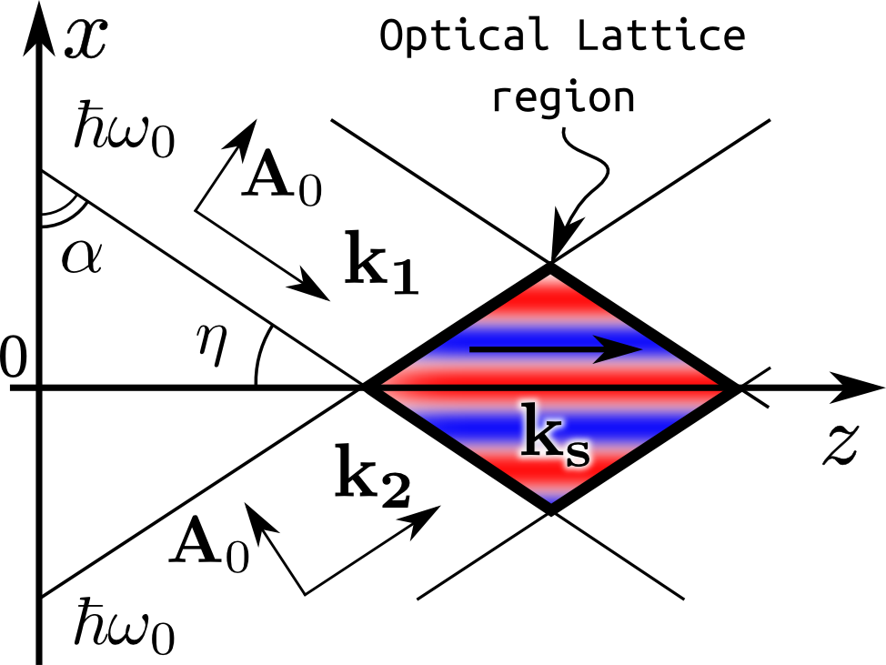
Let us consider two crossed laser beams of the frequency with the wave vectors and , which lie in the plane at the acute angles with respect to the direction (see Fig. 1). Let the electron move in the combined laser filed, which is situated in the region where two laser beams form a standing wave structure. Using plane wave approximation, the electromagnetic field in some region of beams overlapping could be described by a set of equations
| (2) |
where are the absolute values of appropriate components, and is the longitudinal vector potential amplitude.
This structure is similar in some way to the crystal lattice, seen by a high-velocity projectile, that is a set of crystal nodes, forming crystallographic planes and axes. The standing waves can be represented as the effective potential wells, the channels, periodically situated in a transverse plane that can trap the electron at specific conditions. The non-relativistic electron trajectory can be classically derived with the help of the well known Kapitza formalism Landau and Lifshitz (1988), within which the trajectory of a channeled electron could be presented as a sum of slow channeling oscillations and rapid small amplitude oscillations. Such approach allows one to write down the analytical expression for channeled electron trajectory in the case of small channeling oscillations near the channel bottom. For the case of large amplitude channeling oscillations the motion equation can not be linearized. Thus, only qualitative estimations and computer simulations are feasible.
II.2 Relativistic factor
It should be underlined that to use Kapitza method becomes impossible directly for relativistic electrons since their speed is comparable with the speed of light. However, one may switch to new variables
| (3) |
where is the electron initial longitudinal speed (), is the generalized momentum projection on the axis. Thus, for the electron in the field characterized by the vector-potential the motion equations are
| (4) |
| (5) |
where is the kinematic momentum, is delta Kronecker symbol. This equations could be solved within Kapitza method, i.e. the electron trajectory as mentioned above may be expressed as a sum of slow and rapid oscillations . The same is true for electron momentum . The right hand side of Eq. (4) then may be written in the following way , thus – taking into account that – the motion equations are spitted for slow oscillations
| (6) |
and rapid oscillations
| (7) |
where . The averaged longitudinal impulse in the system is constant
| (8) |
Averaging by rapid oscillations one derives the effective potential expression
| (9) |
| (10) |
where and positive means that the electron moves in the direction of , while negative – in opposite direction.
In the case of equal circular lasers polarization (for both lasers it is either right-handed or left-handed) in the same beams geometry the use of the described method yields in the following effective potential amplitude expression
| (11) |
The method is applicable to a system only when both rapid momentum and trajectory oscillations are considerably less then the slow ones: and . The particle trajectory in such a system is characterized by frequency for channeling oscillations (within standing wave structure) and frequency for rapid oscillations due to the particle interaction with the interference laser field.
II.3 Potential inversion
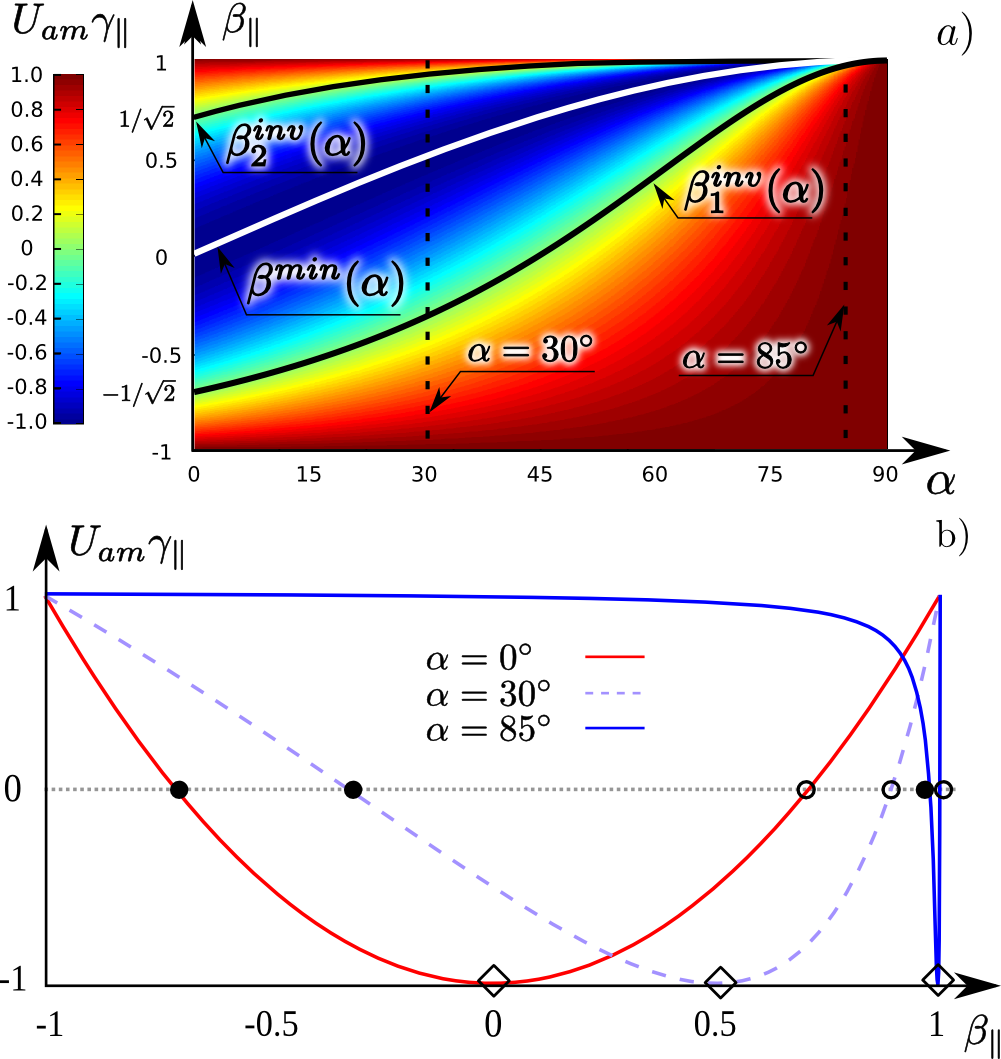
The above derived expressions (9) and (10) describe the potential in the region of two p-polarized laser crossing beams. For the beams are counterpropagating and the geometry is similar to that considered in Kaplan and Pokrovsky (2005); Pokrovsky and Kaplan (2005); Smorenburg et al. (2011). The potential amplitude in this case is positive for and negative otherwise. This corresponds to the results reported in Kaplan and Pokrovsky (2005); Pokrovsky and Kaplan (2005); Smorenburg et al. (2011) and means that for an electron moving at the speed no periodic potential is formed. Let us call these two values the “inversion speed” . And is the electron speed value for which at chosen the value of becomes minimal. When the electron speed is , the regions of interference electric field peaks are scattering for it. And for these regions are attracting. This potential inversion is observed only for p-polarized crossed laser beams.
The expressions (9) and (10) covers arbitrary lasers crossing angles and the analysis of Eq. (10) shows that the values of inversion speed may be expressed by
| (12) |
This function is presented in Fig. 2.a. One may see that only for . Varying causes shift of the range to positive region (see Fig. 2.b). This means that an electron with in the region of two laser beams overlapping at the angle of () is affected by no ponderomotive force (), whereas an electron with could become channeled in the effective potential ().
For the chosen electron longitudinal energy values of lasers crossing angle , for which , could be easily derived from the expression (10)
| (13) |
Such electron in the field of two lasers crossed at the angle of with oscillates near the transverse electric field peaks. On the other hand, channeled electron with (or ) oscillates near the transverse electric field nodes plane.
In Fig. 3 the projections of phase space trajectories onto the plane of transverse momentum and coordinate are presented for both channeled and over-barrier electrons in the field of laser beams crossed at the angle of (). The inner closed curves (in blue) correspond to channeled electrons with transverse energies less than potential well height. Over-barrier electrons (in red) are characterized by transverse energies greater than the barrier height and not limited within the channels.
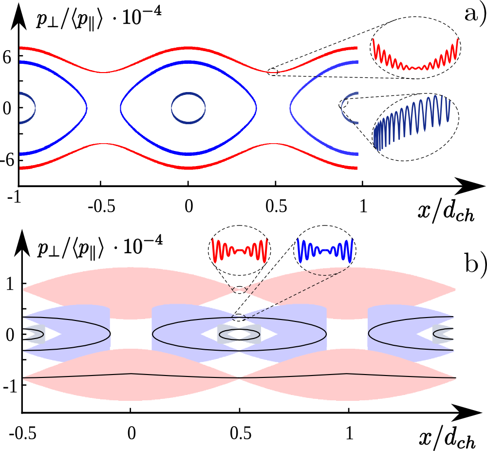
For electron with the channel borders are situated at and, correspondingly, the channel centers – at (see Fig. 3,a). On the contrary, electron with longitudinal velocity could be trapped by the channels, central axes of which are placed at (see Fig. 3,b), where
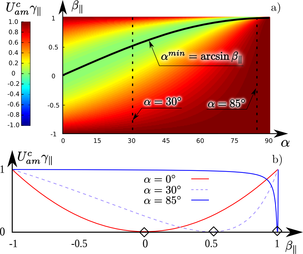
Notably, the effective potential for the case of equal circular lasers polarization normalized to unity has the form exactly similar to Eq. (10) but its minimal value is zero (see Fig. 4). This case for was considered in Kaplan and Pokrovsky (2005); Pokrovsky and Kaplan (2005); Smorenburg et al. (2011) previously, providing the same results. But the expression (11) describes the potential amplitude for arbitrary showing that an electron in the field of circularly polarized lasers crossed at the angle of feels no effective potential, and no inversion is observed for circularly polarized laser beams. This is the main difference comparing to the p-polarization case.
For details, in the supplemental materials sup one can find two animations of channeled electron dynamics numerical simulations. These results were received by motion equations integration for the electron in the field of p-polarized and circularly polarized electromagnetic waves. The 4th order Runge-Kutta method was used. The projectile longitudinal velocity varies from to just as if the additional longitudinal electric field was imposed on the region. Current electron longitudinal speed is shown in the upper region of the video. Spatial distribution of the normalized potential distribution is shown for every moment of time in the right region of the video. In the main area averaged transverse oscillations of the electron is put onto the current potential distribution presented in color.
III Channeled electrons radiation
Obviously, the possibility of charged beam channeling in electromagnetic lattices becomes rather interesting due to the ability of beams shaping by means of tools based on this process. Moreover, speaking on possible applications of the interaction under consideration one should outline that it can be used as a promising tunable source of intense radiation. The radiation spectrum of a charged particle emitting in a crossed laser field is characterized by two peak frequencies and Frolov et al. (2014a), where were defined before. Both of them being measured in the forward direction () are shifted by the factor of due to the Doppler effect. The first one corresponding to slow channeling electron oscillations in the potential well of a system does not depend on the laser frequency . The radiation frequency is caused by the electron interaction with the interference laser beams field. Hence, is strictly defined by the electron velocity as well as by the wave vectors and . The intensity of electromagnetic radiation by a laser-channeled electron can be described by the 4-potential
| (14) |
where is the 4-current, is the Green function. The field can be found in far-field zone and represented as a sum of spherical monochromatic waves. Taking into account that relativistic particle emits radiation in a narrow forward directed solid cone, one could define the analytical expression for radiation spectrum of relativistic channeled electron moving near the bottom (center) of the cross-laser channel Frolov et al. (2014a)
| (15) |
where is the radiation frequency, is the amplitude of channeling oscillations, and is the amplitude of rapid oscillations, is the number of -frequency particle oscillations, , and Bagrov et al. (2002); Kumakhov et al. (1991). The results of numerical computations of the electron radiation emitted in the considered system are similar to well known crystal channeling radiation spectra (e.g. see spectra in Frolov et al. (2014a) and Bogdanov et al. (2008)).
Based on previously derived expressions, simple estimations of a single electron radiation yield are presented. For the external laser intensities the maximum of emitted channeling radiation spectral distribution falls on for a channeled electron with . And for the external laser wavelength of crossed at the channels width would be . Total power emitted by the channeled electron can be then evaluated by
| (16) |
for the channeling oscillations amplitude .
One should note that, first, since both electron and laser parameters are chosen to meet parametric resonance conditions Andreev and Akhmanov (1991) the radiation wavelength is equal to the external laser one. Hence, this could be interesting as radiation amplification mechanism. Moreover, due to rather wide channel width it becomes possible to use a large bunch of, for instance, electrons, radiating coherently with a power
| (17) |
As seen, in the case of initial laser intensity of the total radiation power is estimated to be equal to .
Obviously, there are some constraints imposed on channeled electrons. One of them is the bunch divergence. Its critical value could be derived from the channel potential height, and for the parameters above used it can be estimated as (it corresponds to the values of shown in Fig. 3 for over-barrier electrons). In addition, there is an upper limit for the laser intensities to form the channel structure. The limit is caused by the fact that for some laser intensities the rapid electron oscillations become too high allowing the electron to leave the channel independently of its initial transverse velocity (electron dechanneling). This is caused by system transition to chaotic behavior described in Bauer et al. (1995). Kapitza method is no applicable for such regimes which could be observed for different crossing angles as well as laser polarizations. But their investigation seems to be very promising for applications as a future new-type -radiation source when needed intensities will become achievable (see Gonoskov et al. (2014) for details).
IV Summary
Summing up, channeling of an electron in the field of crossed laser beams was reconsidered with a special attention paid to the peculiarities of the interaction potential. The potential derived in terms of classical physics reveals strong dependence on external lasers parameters and their mutual orientation. Moreover, it shows rather complex dependence on the electron longitudinal velocity by its value and direction. For the case of p-polarized lasers, the increase in channeled electron longitudinal velocity from (which corresponds to the opposite to -axis electron motion) to results in the decrease of the potential amplitude down to zero. In the interval the potential becomes scattering and grows to its maximum at . At the following increase of the scattering potential fades away to zero at . For the potential becomes attracting again, growing from zero to its maximum at the end of the interval (this process is shown in sup ).
The averaged potential for the laser beams of equal circular polarization has exactly the same shape as in the case of p-polarized beams. But its minimal value lying on the line is zero, hence, no potential inversion is observed.
The radiation spectrum classically calculated is characterized by two major frequencies: the first one is due to external laser field scattering on relativistic electron, while the second corresponds to the radiation of electron trapped by the effective potential well. The maximum radiation intensity falls on the frequency defined by both electron energy and external laser intensity, while the integral radiated power depends on squared external laser intensity . Combined with high radiation coherence for a channeled electron bunch it can result in a high intensity gain that needs more detailed investigation.
This work was supported by the Ministry of Education and Science of RF in the frames of Competitiveness Growth Program of National Research Nuclear University MEPhI, Agreement 02.A03.21.0005 and the Dept. for Education and Science of LPI RAS.
References
- Kapitza and Dirac (1933) P. L. Kapitza and P. A. M. Dirac, Math. Proc. Cambridge 29, 297 (1933).
- Shintake (1992) T. Shintake, Nucl. Instr. Meth. Phys. Res., Sect. A 311, 453 (1992).
- Fedorov et al. (1988) M. V. Fedorov, K. B. Oganesyan, and A. M. Prokhorov, Appl. Phys. Lett. 53, 353 (1988).
- Balcou (2010) P. Balcou, Eur. Phys. J. D 59, 525 (2010).
- Andriyash et al. (2011) I. A. Andriyash, P. Balcou, and V. T. Tikhonchuk, Eur. Phys. J. D 65, 533 (2011).
- Andriyash et al. (2012) I. A. Andriyash, E. d’Humières, V. T. Tikhonchuk, and P. Balcou, Phys. Rev. Lett. 109, 244802 (2012).
- Andriyash et al. (2013a) I. A. Andriyash, E. d’Humières, V. T. Tikhonchuk, and P. Balcou, J. Phys.: Conf. Ser. 414, 012008 (2013a).
- Bertolotti et al. (1986) M. Bertolotti, C. Sibilia, and L. Fuli, in Trends in Quantum Electronics, edited by A. M. Prokhorov and I. Ursu (Springer Berlin Heidelberg, 1986) pp. 155–159.
- Andreev and Akhmanov (1991) A. V. Andreev and S. A. Akhmanov, Zh. Eksp. Teor. Fiz., Pis’ma Red. 53, 18 (1991).
- Frolov et al. (2014a) E. N. Frolov, A. V. Dik, and S. B. Dabagov, J. Phys.: Conf. Ser. 517, 012002 (2014a).
- Kaplan and Pokrovsky (2005) A. E. Kaplan and A. L. Pokrovsky, Phys. Rev. Lett. 95, 053601 (2005).
- Pokrovsky and Kaplan (2005) A. L. Pokrovsky and A. E. Kaplan, Phys. Rev. A 72, 043401 (2005).
- Smorenburg et al. (2011) P. W. Smorenburg, J. H. M. Kanters, A. Lassise, G. J. H. Brussaard, L. P. J. Kamp, and O. J. Luiten, Phys. Rev. A 83, 063810 (2011).
- Lindhard (1965) J. Lindhard, Mat.-Fys. Medd. - K. Dan. Vidensk. Selsk. 34, 1 (1965).
- Gemmell (1974) D. S. Gemmell, Rev. Mod. Phys. 46, 129 (1974).
- Kumakhov (1976) M. A. Kumakhov, Phys. Lett. A 57, 17 (1976).
- Bukreeva et al. (2006) I. Bukreeva, A. Popov, D. Pelliccia, A. Cedola, S. B. Dabagov, and S. Lagomarsino, Phys. Rev. Lett. 97, 184801 (2006).
- Dabagov (2003) S. B. Dabagov, Usp. Fiz. Nauk. 46, 1053 (2003).
- Zhevago and Glebov (2003) N. K. Zhevago and V. I. Glebov, Phys. Lett. A 310, 301 (2003).
- Klimov and Letokhov (1996) V. V. Klimov and V. S. Letokhov, Phys. Lett. A 222, 424 (1996).
- Karabarbounis et al. (2013) A. Karabarbounis, S. Sarros, and C. Trikalinos, Nucl. Instr. Meth. Phys. Res., Sect. B 316, 160 (2013).
- Esarey et al. (2002) E. Esarey, B. A. Shadwick, P. Catravas, and W. P. Leemans, Phys. Rev. E 65, 056505 (2002).
- Kostyukov et al. (2003) I. Kostyukov, S. Kiselev, and A. Pukhov, Phys. Plasmas 10, 4818 (2003).
- Faure et al. (2010) J. Faure, C. Rechatin, O. Lundh, L. Ammoura, and V. Malka, Phys. Plasmas 17, 083107 (2010).
- Dik et al. (2013) A. V. Dik, A. Z. Ligidov, and S. B. Dabagov, Nucl. Instr. Meth. Phys. Res., Sect. B 309, 210 (2013).
- Frolov et al. (2013) E. N. Frolov, A. V. Dik, and S. B. Dabagov, Nucl. Instr. Meth. Phys. Res., Sect. B 309, 157 (2013).
- Gaponov and Miller (1958) A. V. Gaponov and M. A. Miller, Zh. Eksp. Teor. Fiz. 34, 242 (1958), in Russian.
- Bolotovskii and Serov (1994) B. M. Bolotovskii and A. V. Serov, Usp. Fiz. Nauk. 37, 515 (1994).
- Andriyash et al. (2013b) I. A. Andriyash, E. d’Humières, V. T. Tikhonchuk, and P. Balcou, Phys. Rev. Spec. Top.–Accel. Beams 16, 100703 (2013b).
- Artru et al. (2007) X. Artru, K. A. Ispirian, and M. K. Ispiryan, arXiv.org, e-Print Arch., Phys. (2007), arXiv:0707.0148 .
- Frolov et al. (2014b) E. N. Frolov, A. V. Dik, S. B. Dabagov, and K. P. Artyomov, J. Phys.: Conf. Ser. 552, 012035 (2014b).
- Elishev et al. (1979) A. F. Elishev, N. A. Filatova, V. M. Golovatyuk, I. M. Ivanchenko, R. B. Kadyrov, N. N. Karpenko, V. V. Korenkov, T. S. Nigmanov, V. D. Riabtsov, M. D. Shafranov, B. Sitar, A. E. Senner, B. M. Starchenko, V. A. Sutulin, I. A. Tyapkin, E. N. Tsyganov, D. V. Uralsky, A. S. Vodopianov, A. Forycki, Z. Guzik, J. Wojtkowska, R. Zelazny, I. A. Grishaev, G. D. Kovalenko, B. I. Shramenko, M. D. Bavizhev, N. K. Bulgakov, V. V. Avdeichikov, R. A. J. Carrigan, T. E. Toohig, W. M. Gibson, I.-J. Kim, J. Phelps, and C. R. Sun, Phys. Lett. B 88, 387 (1979).
- Fuli et al. (1986) L. Fuli, M. Bertolotti, C. Sibilia, C. Ronsivalle, and G. D’Auria, Laser Part. Beams 5, 557 (1986).
- Landau and Lifshitz (1988) L. D. Landau and E. M. Lifshitz, Mechanics, Russian ed. (Nauka, 1988).
- (35) See Supplemental Materials at HTTP://…for commented video of electron channeling oscillations in electromagnetic lattice.
- Bagrov et al. (2002) V. G. Bagrov, V. A. Bordovitsyn, V. Y. Epp, Y. L. Pivovarov, A. V. Borisov, O. F. Dorofeev, V. C. Zhukov, G. S. Bisnovatyi-Kogan, and O. V. Shorokhov, Radiation Theory of Relativistic Particles, Russian ed. (Fizmatlit, 2002) pp. 89–93.
- Kumakhov et al. (1991) M. A. Kumakhov, R. Wedell, et al., Radiation of relativistic light particles during interaction with single crystals (Spektrum Akademischer Verlag Heidelberg-Berlin-New York, 1991).
- Bogdanov et al. (2008) O. V. Bogdanov, K. B. Korotchenko, and Y. L. Pivovarov, J. Phys. B 41, 055004 (2008).
- Bauer et al. (1995) D. Bauer, P. Mulser, and W. H. Steeb, Phys. Rev. Lett. 75, 4622 (1995).
- Gonoskov et al. (2014) A. Gonoskov, A. Bashinov, I. Gonoskov, C. Harvey, A. Ilderton, A. Kim, M. Marklund, G. Mourou, and A. Sergeev, Phys. Rev. Lett. 113, 014801 (2014).