Design, optimization and characterization of the light concentrators of the single-mirror small size telescopes of the Cherenkov Telescope Array.
Abstract
The focal-plane camera of -ray telescopes frequently uses light concentrators in front of light sensors. The purpose of these concentrators is to increase the effective area of the camera as well as to reduce the stray light coming at large incident angles. These light concentrators are usually based on the Winston cone design. In this contribution we present the design of an hexagonal hollow light concentrator with a lateral profile optimized using a cubic Bézier function to achieve a higher collection efficiency in the angular region of interest. The design presented here is optimized for a Davies-Cotton telescope with primary mirror of about 4 meters of diameter and focal length of 5.6 m. The described concentrators are part of an innovative camera made up of silicon-photomultipliers sensors, although a similar approach can be used for other sizes of single-mirror telescopes with different camera sensors, including photomultipliers. The challenge of our approach is to achieve a cost-effective design suitable for standard industrial productions of both the plastic concentrator substrate and the reflective coating. At the same time we maximize the optical performance. In this paper we also describe the optical set-up to measure the absolute collection efficiency of the light guides and demonstrate our good understanding of the measured data using a professional light tracing simulation.
keywords:
light concentrator, optical element, Winston cone, Cherenkov astronomy, Imaging Air Cherenkov Telescopes (IACTs)1 Introduction
The Cherenkov Telescope Array project (CTA) [8] will be the next generation observatory in -ray astronomy. It will consist of two arrays of imaging atmospheric Cherenkov telescopes (IACTs) of different sizes to be installed in the two hemispheres. The southern array will be composed of few Large Size Telescopes (LSTs) of m diameter, about 25 Middle Size Telescopes (MSTs) of about 12 m diameter and about 70 Small Size Telescopes (SSTs) of m diameter. An arrangement over an area of the order of few km2 will make it possible to cover about 2 decades in energy, from about 20 GeV to 300 TeV, with an improved sensitivity by about a factor of 15 compared to existing experiments which also operate in a smaller energy range.
Reflective light concentrators are a common element used in IACTs in order to increase the collection area of camera pixels [1, 6, 2, 3]. The cross-section of these concentrators is usually hexagon-shaped so that they can be arranged in an array with equal distance between all pixel centers. If their mutual distance is kept constant along the camera, the response of the pixels for different orientations of the shower images is geometrically unbiased. These light concentrators are designed to maximize the collection efficiency of incoming rays within the angular range subtended by the primary mirror and the camera while at the same time limiting the amount of light from the night sky background (NSB) at larger angles. The NSB arises from airglow, stars, nearby cities, etc. and usually reaches the camera sensors directly without reflecting first on the telescope’s primary mirror. These trajectories can be rejected geometrically by optimizing the shape of the light concentrator. The spectrum of the NSB is also different from the Cherenkov spectrum, the latter peaks at 330 nm and begins to be dominated at wavelengths larger than 600 nm by the NSB that extends in the infrared. Therefore the wavelength dependency of the reflectivity material of the light concentrator can be optimized to further reduce this background.
The Small Size Telescopes of CTA are characterized by a wide field-of-view (FoV) of about which is essential for the physics goals of these telescopes, such as the Galactic Plane survey, study of spectra to discriminate hadronic against electromagnetic emissions, and the search for the Galactic PeVatrons which produce the Galactic cosmic rays up to the knee at a few PeV [9]. In the following we will explore the design of a light concentrator suitable for a single mirror IACT and so we present it as a feasible solution for the SSTs. Particularly we consider the Davies-Cotton design which provides a good imaging over a wide FoV. The dispersion in the arrival time of photons introduced by this design for small dish telescopes is negligible compared to the intrinsic dispersion of photons and therefore it is a suitable solution for the SSTs. We pay particular attention to the cost-effectiveness of our proposal and to the industrial producibility of the light concentrators given the large number (around 70) of the SSTs planned for CTA. Assuming the number of pixels for each camera to be around 1’300, the total number of light concentrators to be produced for the SSTs in CTA will be of the order of 91’000. Therefore it is clear that the design has not only to address the optical performance but has also the industrial producibility.
The outline of the paper is the following: in Section 2 we review the Davies-Cotton telescope design and evaluate the parameters needed for a wide FoV telescope with a 4 m diameter dish. We review the requirements of light concentrators for this kind of design. In Section 3 we show how, using a professional ray-tracing simulation, we can optimize the geometrical shape of the light concentrator using cubic Bézier curves. We compare this design with the Compound Parabolic Concentrator (CPC), also called Winston’s Cone [7]. Even if solid concentrators can achieve larger compression factors than hollow ones [3, 4, 5], the former start to suffer from limited transmissivity due to the thickness of 37 mm necessary in this design for the SST. In addition, hollow cones allow us to use a reflective coating optimized for high reflectivity in the wavelength region of interest. We consider a few coating options and their impact on the collection efficiency. Section 4 shows the optical measurements performed with the first prototypes and their comparison with simulations. Conclusions are given in Sec. 5.
2 Design of a Davies-Cotton telescope.
As already stated, the telescope design has a primary mirror diameter, D of 4 m, a FoV of 9∘, and a focal-length f of 5.6 m. The focal-length is usually selected to keep the f/D in the range 1.21.4 where optical aberrations are small enough to facilitate good imaging on the camera.
The IACT reflector is usually segmented into individual mirror facets and this finite-facet-size enhances the optical aberrations of the system. However, if one ignores these effects and considers only the global aberrations of the Davies-Cotton design, the Point Spread Function (PSF) of photons can be described analytically [10]. The Root Mean Square (RMS) of these analytical expressions for a Davies-Cotton design are shown in Fig. 1 for both the tangential and sagittal direction as a function the f/D of the telescope.
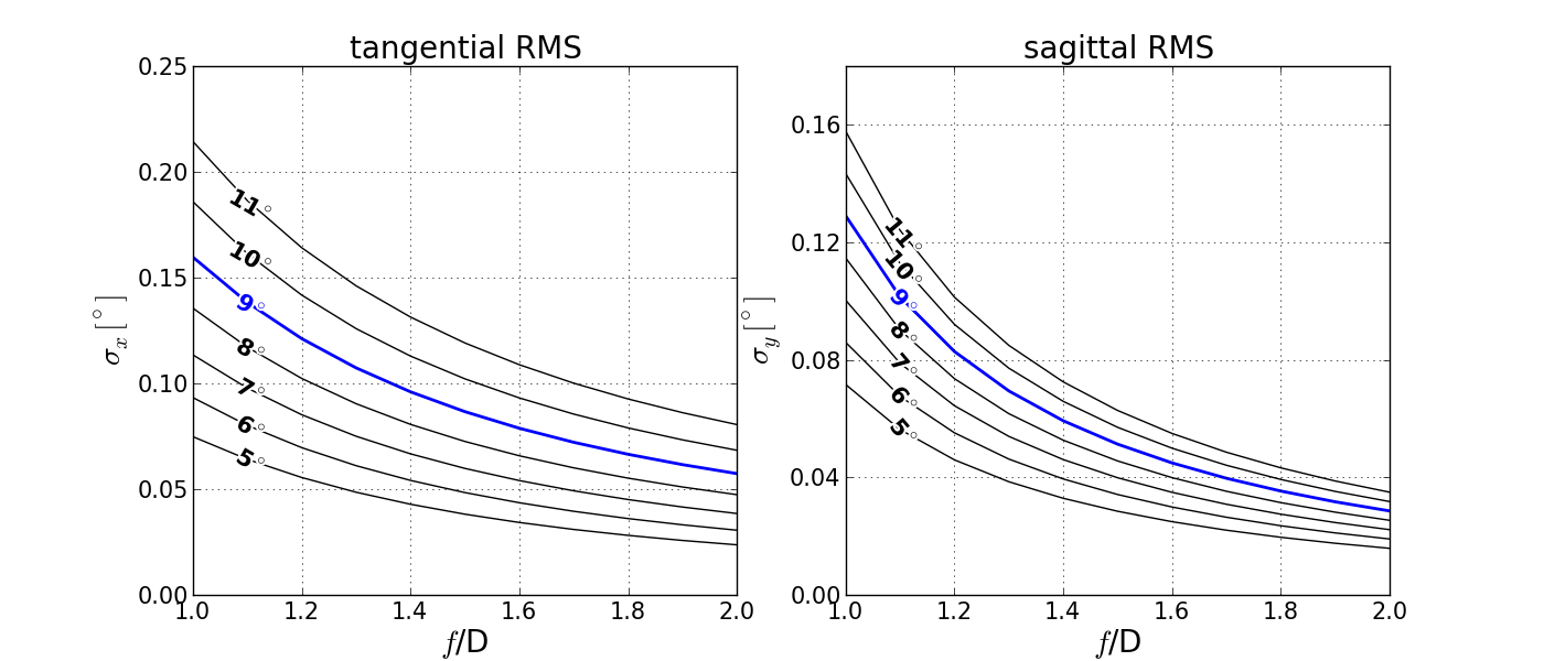
The RMS of the PSF can be used to define the optimum angular size of the pixel of the camera. A compromise is to take an angular pixel size, p, that is 4 times the minimum of the two RMS. This guarantees the inclusion of 95.4% of the photons from a source assuming a gaussian distribution for the PSF.
As already mentioned, one of the goals of the light concentrators is to reduce the stray light from the NSB. The camera is pointing to the dish mirror of the telescope and therefore any ray of light that arrives at the camera without undergoing any reflection on the mirror is considered to be stray light. The light concentrators can veto the light that comes with an angle greater than the one subtended by the mirror dish and the camera. This angle is usually referred to as the cutoff angle . Both the angular pixel and the cutoff angle depend on and the FoV. In particular is given by:
| (1) |
where, D, refers to the mirror diameter and Dc to the camera diameter. Figure 2 shows both the angular pixel size, p and the cutoff angle , as a function of the the f/D for a telescope of 4 m-dish mirror. For our telescope, the ratio f/D was selected to be 1.4.
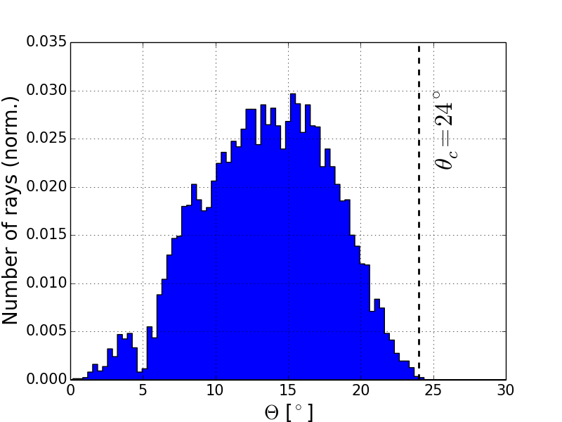
As visible in Fig. 2 the resulting angular pixel size is about 0.25∘ and the resulting desirable cutoff angle for the light concentrator is . In reality, cameras from IACTs might not have a circular shape. In order to verify that the geometrical estimated cutoff angle from Eq. 1 covers all the incident angles of light reflecting on the mirror a raytracing simulation of the telescope optical system was performed. Figure 3 shows the angular distribution of rays arriving on to the camera plane after reflecting on the primary mirror. As confirmed by the simulation, no ray of light reaches the camera plane at angles .
The angular pixel size fixes the input aperture area of the concentrator, , while the cutoff angle fixes the exit aperture area . In Ref. [7], R. Winston proposed the two-dimensional Compound Parabolic Concentrator (CPC) as an ideal concentrator that reaches the maximum concentrator ratio given by:
| (2) |
This ideal concentrator achieves a 100% collection efficiency for incident angles while for angles no incident ray reaches the exit aperture of the concentrator. In three-dimensions however the CPC design departs from the ideal case as rays that enter tangentially to the side walls may follow spiral paths and may suffer many reflection losses reducing the collection efficiency.
The idea of using Bézier curves in the profile shape of the concentrator in order to improve the collection efficiency was first demonstrated in [11]. Here we follow the same approach where starting from a CPC design the geometry is optimized using a cubic Bézier curve. The details of this optimization are described in the next section.
3 Simulations
For the simulation and geometrical optimization of the light concentrator we used the Zemax111www.radiantzemax.com software. This package is designed to provide a tool for optical and illumination designs. It also includes an optimization engine which makes it possible to reshape the sides of the light concentrator to achieve the desirable figure of merit.
3.1 Geometrical optimization
As explained in Sec. 2 we started from the CPC design which means that the size of the entrance aperture, , and exit aperture, , as well as the length of the concentrator are selected according to the ideal 2-dimensional design proposed in Ref. [7]. The cross-section of the concentrator has an hexagonal shape since this helps to reduce the dead areas in the camera as opposed to a circular concentrator while at the same time keeping the same center-to-center distance of pixels. Figure 4 shows the dimensions for the entrance aperture and the output aperture following the geometrical constraints of an open CPC.
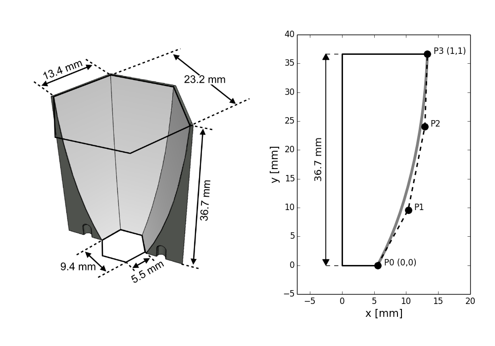
The sides of the hexagonal concentrator are parametrized using a cubic Bézier curve given by:
| (3) |
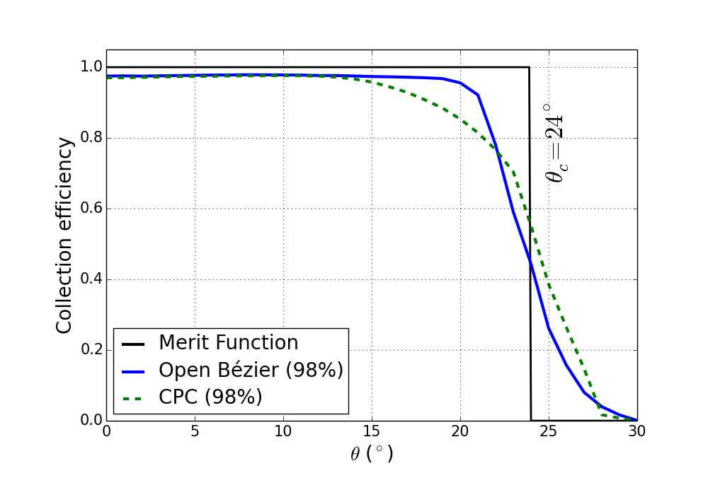
the Bézier curve is described by one parameter, t, and four control points . The control points and define the output and input aperture sizes respectively, as well as the length of the collector (see Fig. 4) and therefore they are fixed. In our case geometrical optimization is achieved by moving the control points and . We used the Zemax optimization algorithm based on actively damped least squares to improve the performance of the optical system. The merit function of the optimization was set to the collection efficiency of an ideal concentrator (see Fig. 5). A similar approach was followed in [11] by using a brute force optimization by testing several realizations of the light concentrator.
| Point | Coordinates (mm) |
|---|---|
| (5.540, 0) | |
| (6.434, 2.272) | |
| (12.153, 24.048) | |
| (13.320, 36.658) |
The results of the optimization are summarized in Tab. 1. Fig. 5 shows the comparison of the collection efficiency with respect to the standard CPC. In both cases an ideal 98% reflectivity has been assumed for the reflective material on the internal surface of the concentrator. The overall gain in efficiency for angles is about 3% while on the other hand the reduction of efficiency for angles is about 30% which helps to improve the suppression of background light beyond the cutoff angle.
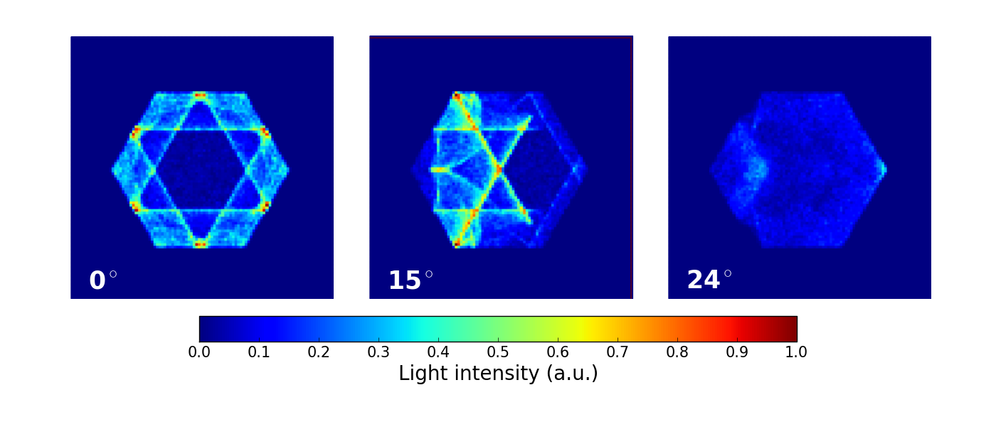
Both the CPC and the Bézier are non-imaging concentrators, meaning that the distribution of rays at the exit aperture does not reproduce the distribution of rays entering the concentrator. Fig. 6 shows the spatial distribution of photons at the exit aperture of the Bézier optimized concentrator when a planar waveform of photons enters the concentrator at three different angles of incidence. The observed non-uniformity will be partly smeared out by the arrival angle distribution of light on the camera plane (see Fig. 3) for different azimuthal angles.
3.2 Coating simulations
An important element of open light concentrators is the reflectivity properties of the material used to coat the inner surface of the concentrator. In the previous section we assumed an ideal 98% reflectivity with no angular or wavelength dependency. Such an ideal reflector does not exist and therefore more realistic coatings have been simulated using Zemax until the optimum coating for this application was selected.
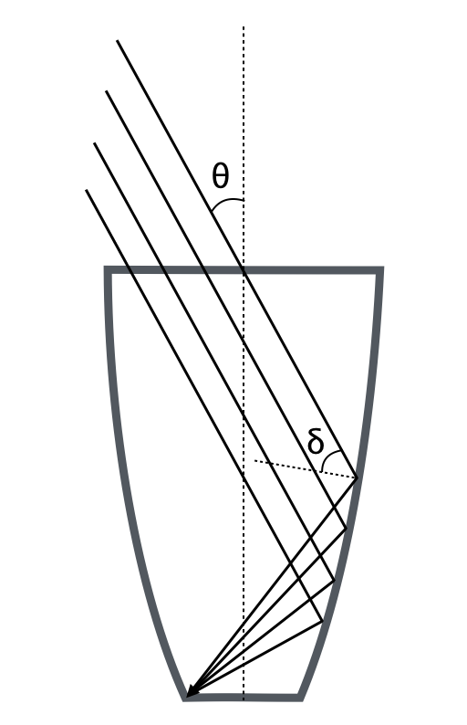
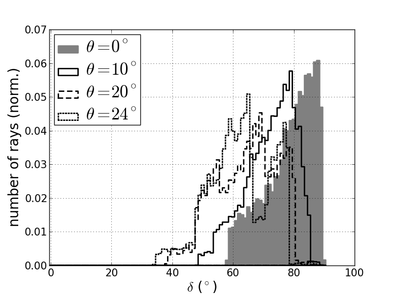
The angular dependency of the coating reflectivity has a large impact on the overall collection efficiency of the concentrator. Using simulations we were able to estimate the angular distribution of rays on the inner surface of the concentrator. Figure 7 (left) shows a 2-dimensional schematic view of how rays entering into the concentrator at an angle hit the inner surface at an angle . The right plot on the same Fig. 7 shows the distribution of angles in the 3-dimensional case computed from simulations for different incident angles . Only rays that reach the output aperture are considered. Absorption effects due to several reflections are not taken into account in this plot. As can be seen, rays entering perpendicularly () will impinge on the light concentrator always at angles . For rays arriving with an incident angle equal to the cutoff angle, , all internal reflections occur at angles . Therefore the reflectivity of the coating material for angles is not important for our application. This is an important information as manufactures of reflective coatings usually seek to have high reflectivity at normal incident angles, while in our case we aim at high reflectivity at large angles.
|
The wavelength dependency is also important to optimize the overall efficiency of the light concentrator. In our application we are interested in the wavelength range of the Cherenkov spectrum which peaks at the blue and UV light [8] ( nm), strongly decreases below 290 nm due to atmospheric transmission effects, and falls off as towards longer wavelength (see Fig. 8). The selected coating needs to have an optimum reflectivity in the wavelength region of the signal convoluted to the response of the photosensor that will be placed at the exit aperture of the light concentrator. In order to include these two features while doing the coating optimization using simulation the Cherenkov spectrum and the detector wavelength response we simulated a light source with a spectrum which is a convolution of the two spectra. Since our study is focused on the SST design using a novel camera equipped with SiPMs solid state sensors (also called Geiger-APD) [12] we used the photo-detection efficiency (PDE) of the SiPMs222The PDE of SiPMs is defined as the product of the Quantum Efficiency (QE), the fill factor (the ratio of sensitive pixel size over full pixel size, typically of about 60%) and the avalanche probability (number of excited pixels/number of pixels hit by photons). which is wavelength dependent [12].
In this study we use the PDE of a SiPM from Hamamatsu model 10985_050C333www.hamamatsu.org. The spectrum resulting from the convolution of the Cherenkov light spectrum and the sensor PDE can be seen in Fig. 8. This spectrum has a maximum at wavelengths around 400 nm and therefore the best coating needs to be optimized for those wavelengths. The NSB on the other hand increases at higher wavelengths towards the infra-red light [8].
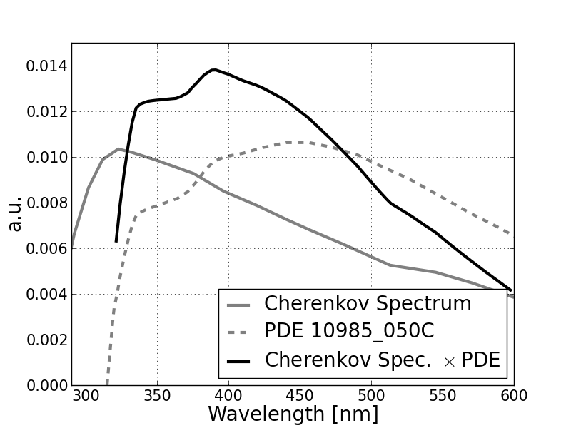
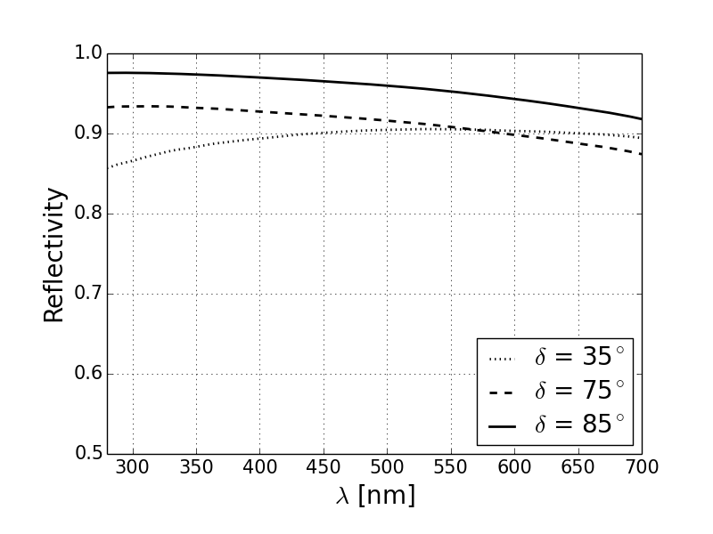
Figure 9 shows the reflectivity of one of the tested materials as a function of wavelength, for different incident angles, . This coating provided by Thin Film Physics444THIN FILM PHYSICS (TFP), Regensdorf, Switzerland. is made of Aluminum with superimposed dichroic layers (R-enhanced coating or Al+R) which protect Aluminum from oxidation and enhance the specular reflection in the region of interest (wavelengths between about 340-550 nm and large incident angles).
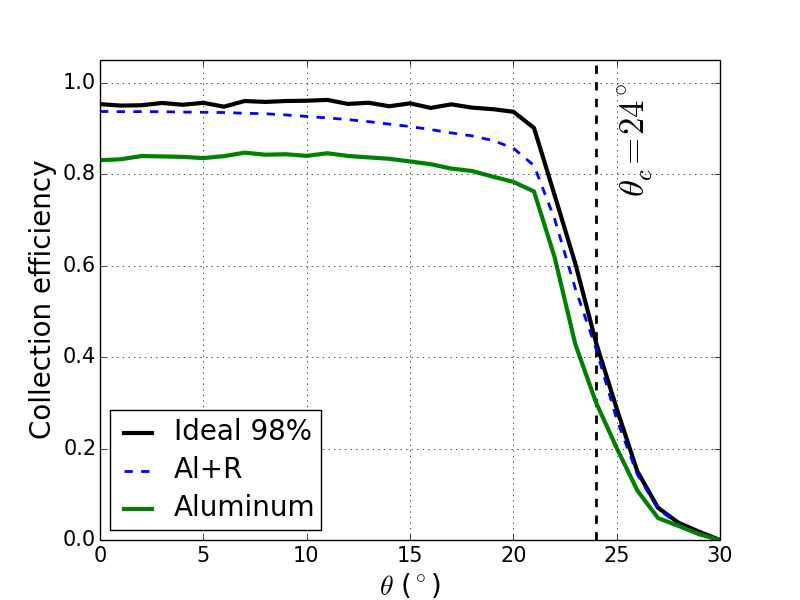
The collection efficiency of the selected coating compared to the ideal reflector of 98% reflectivity can be seen in Fig. 10. Also shown is the collection efficiency achievable with a standard Aluminum coating. The light source used in this comparison emits according to the spectrum shown in Fig. 8. The collection efficiency shown here refers to the efficiency of the light concentrator standalone. In this paper we do not discuss the additional effect of an eventual entrance window on the camera since there are multiple possible solutions that go from thin individual windows on top of single pixels (e.g. 0.7 mm-thick windows) to a common entrance window of the whole camera (e.g. a 3 mm-thick window). Clearly, depending on the thickness of the material, one expects losses due to absorption (with a thickness dependent cutoff) and due to the Fresnel reflection losses on the contact surfaces between air and the material (which are of the order of 8%). Nonetheless, it should be considered that the reflection losses can be compensated by an anti-reflective coating and that a filter can be applied on the window to cut out the wavelength region above 550 nm dominated by the NSB. As a matter of fact, in the case of SiPM, the sensitivity stays higher than for PMTs in this optical-IR region. The combined effect of the light funnels and window will be the subject of a future paper. Moreover there are additional Fresnel losses also on the silicon layer that protects the photosensor also due to the different refractive index encountered by light.
4 Optical measurements of prototypes
A very important element in the design of the light concentrator is the manufacturing of the substrate since this can severely affect the properties and reflectivity of the coating. In our design we use the standard plastic injection molding technique. Being an industrial large scale production technique, each light concentrator can cost a few tenth of euro centimes. The requirement in terms of mechanical precision on the shape and the dimension of the light concentrator are already quite demanding, but the most challenging requirement is on the roughness of the inner surface of the concentrator. As a matter of fact, the coating can just modify/enhance the reflectivity at different angles and wavelengths, but the overall reflectivity is driven by the surface smoothness. The desired level of accuracy and roughness was achieved by optimizing the molding injection and polishing technique.
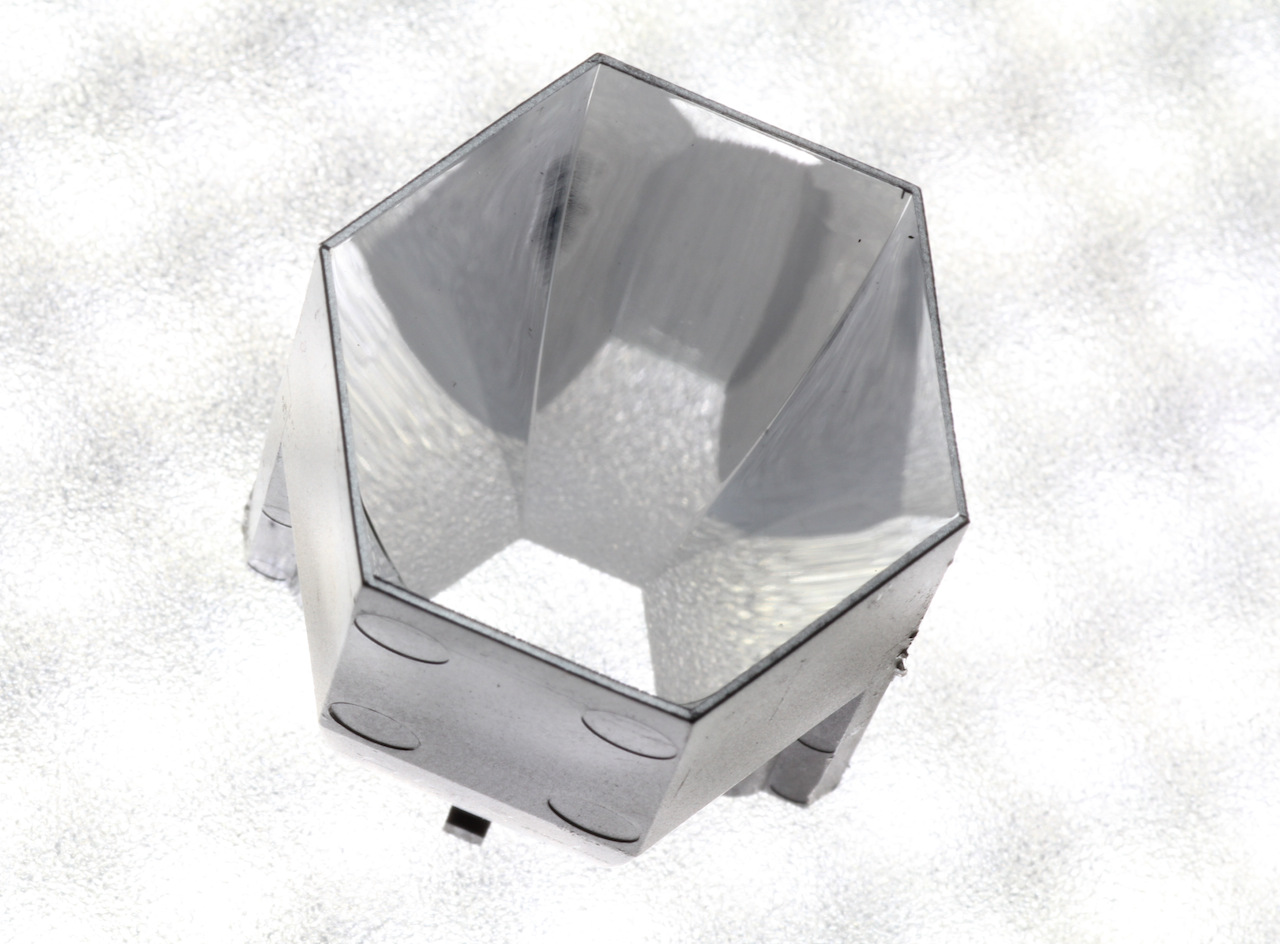
The coating deposition was also challenging since the main difficulty relies on the fact that the technology works perfectly on flat surface but it becomes difficult on strongly curved surfaces as in our light concentrator. In order to facilitate the deposit of the coating, the light concentrator is manufactured in two halves and then assembled together after coating. Figure 11 shows a picture of one of the first prototypes of this technique.
In order to verify that the proposed design achieves the requirements we tested several prototypes in an optical setup by measuring the absolute collection efficiency at different wavelengths as a function of the light incident angle. In this section we will show the measurements corresponding to the optimized concentrator in terms of geometrical design and coating.
 |
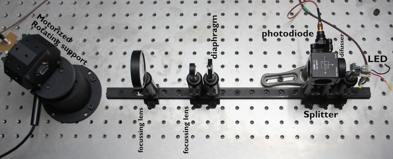 |
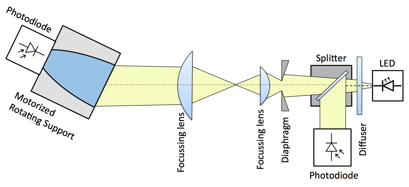
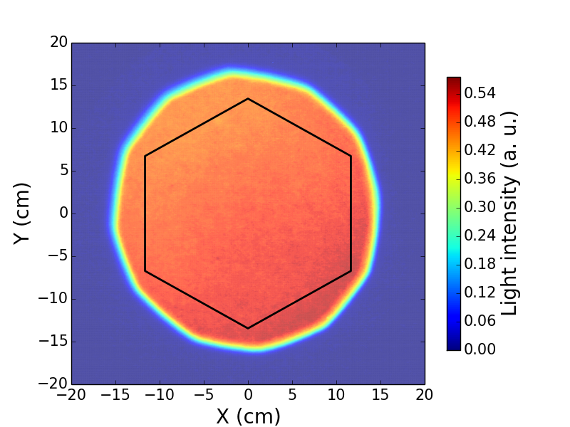
The experimental set-up for this measurement was mounted on an optical bench in order to have a perfectly aligned system. The top panel in Figure 12 shows the scheme of the set-up with the different elements used while the bottom panel shows a picture. The set-up is located in a dark room in order to protect against ambient light. The light concentrator is placed in a motorized rotational stage555Thorlabs: CR1-Z7. This rotational mount offers high-precision motion and it is used to study the angular dependency in the collection efficiency of the light concentrator. The light concentrator is rotated sequentially from 0∘ to 30∘ while illuminated by an LED. The light of the LED is collimated by means of different optical elements in order to have a planar wavefront at the entrance of the concentrator. Figure 13 shows the beam profile as measured at the entrance of the concentrator. This profile was measured by taking a photograph in RAW mode of the footprint of the beam on a white surface at the entrance of the light concentrator using a commercial Canon 60D. The dimension of the beam was selected to guarantee the full coverage of the concentrator entrance aperture. Variations on the uniformity of the light beam inside the region defined by the concentrator aperture are %.
The light of the LED is recorded by a photodiode used for reference after splitting the light beam with a 50/50 splitter. This reference diode allows us to correct from drifts in the light yielded by the LED as a function of time. In order to calculate the absolute collection efficiency of the concentrator, the measurement is done in two steps:
-
1.
Configuration 1. In the first step a photodiode is placed on the rotational stage at the position of the input aperture of the concentrator. The photodiode is then masked with an hexagonal shape of the same dimension as the entrance aperture. With this measurement we record the amount of light that enters into the concentrator as a function of the incident angle.
-
2.
Configuration 2. In the second configuration the light concentrator is placed in the rotation stage and the photodiode is then attached to the rear exit aperture of the concentrator measuring the amount of light that exits the concentrator as a function of the incident angle.
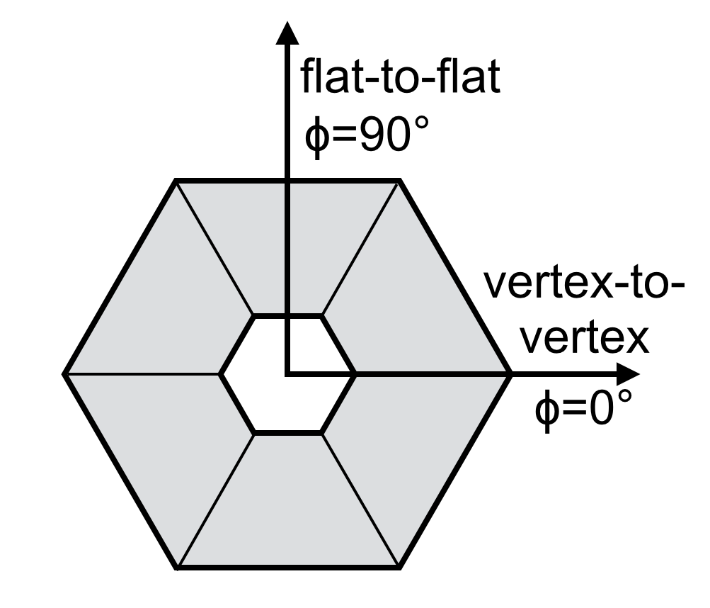
The absolute collection efficiency is given simply by the ratio of the recorded light by the photodiode between configuration 1) and 2). Since the entrance aperture of the light concentrator has an hexagonal shape, there are two major rotational directions as indicated in Fig. 14 left. In one direction the light concentrator rotates along the plane containing the vertex-to-vertex axis of the hexagon, , while the other rotation is along the plane containing the flat-to-flat axis, . Only rotations along these two major directions are allowed in our set-up.
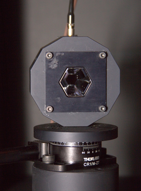
In order to check any possible coating or geometrical asymmetries in the azimuthal angle we perform the measurements of the collection efficiency for all possible major rotation directions: three vertex-to-vertex directions and three flat-to-flat directions. Figure 14 (right) shows a picture of the light concentrator in its holder mounted on the rotational support. The dodecagon shaped holder was manufactured in order to easily change from one rotational axis to another.
|
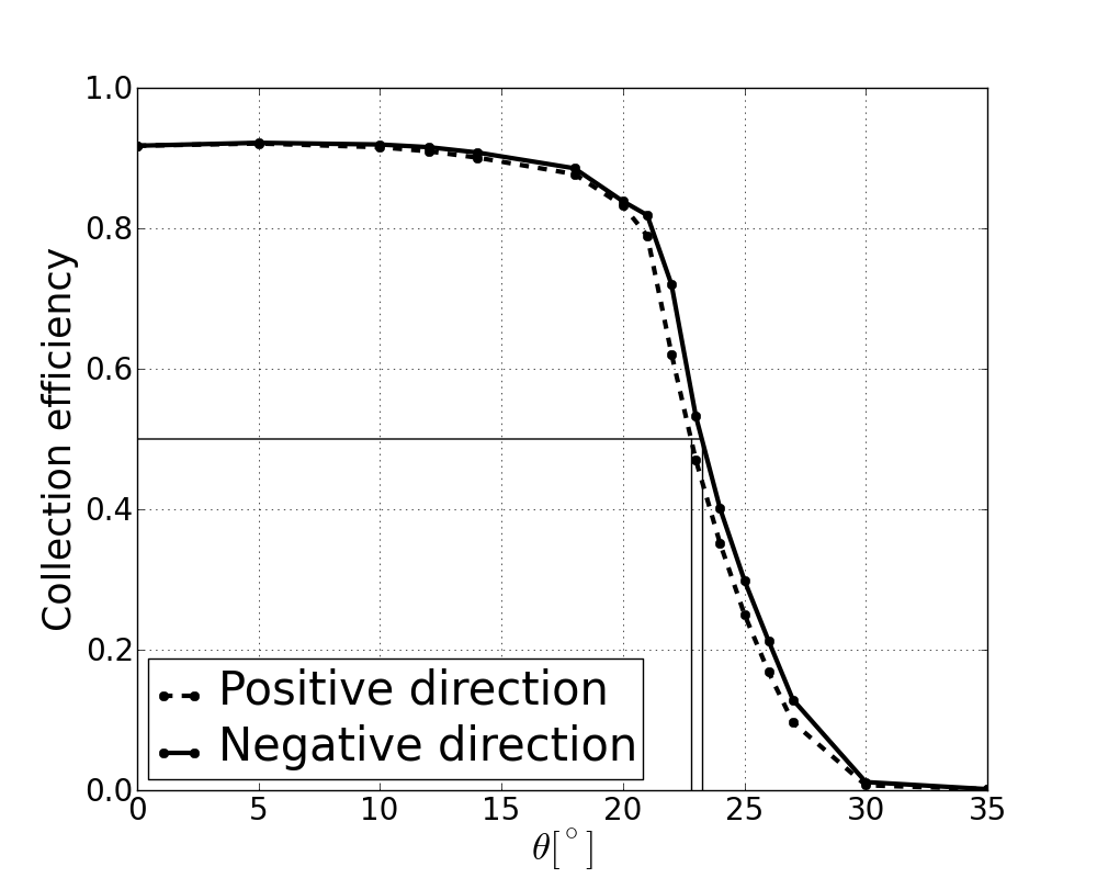
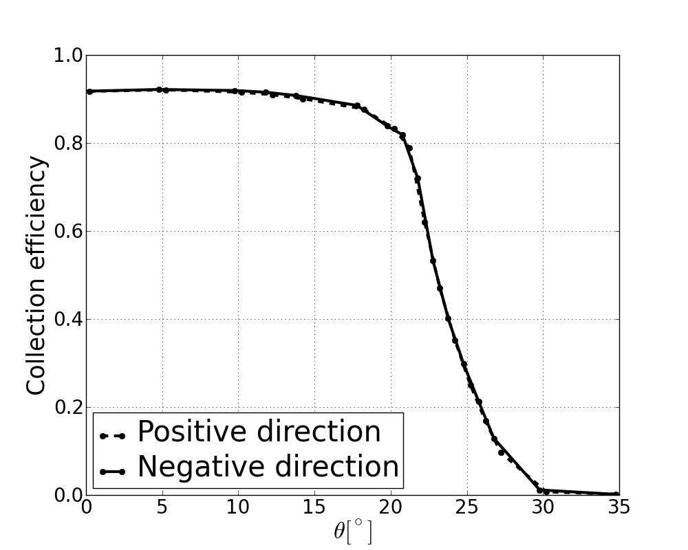
As part of the measurement procedure we must correctly define the 0-angle of the system. In order to align the optical system we first perform an estimation of the zero by looking at the photon distribution measured by the photodiode as a function of angle when a pin-hole of 0.5 cm is placed on top of it. This distribution is strongly peaked and the maximum is used to define the zero of the system. In addition, each collection efficiency measurement is performed in an angular range from -35∘ to 35∘, i.e., from the negative to positive angles. This allows us to correct for the zero of the system by simply applying an angular offset that superimpose the positive-angle values of the collection efficiency with the negative-angle values. Figure 15 shows this offset correction procedure in one single measurement (flat-to-flat).
|
4.1 Results
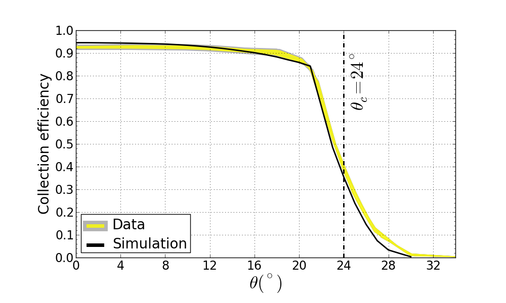
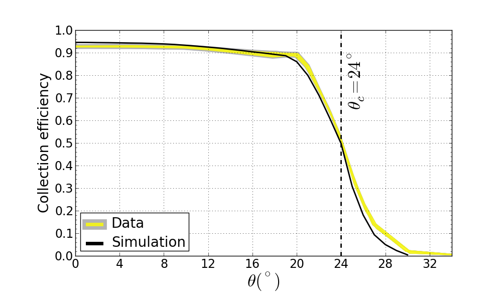
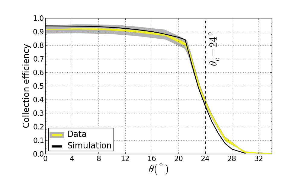
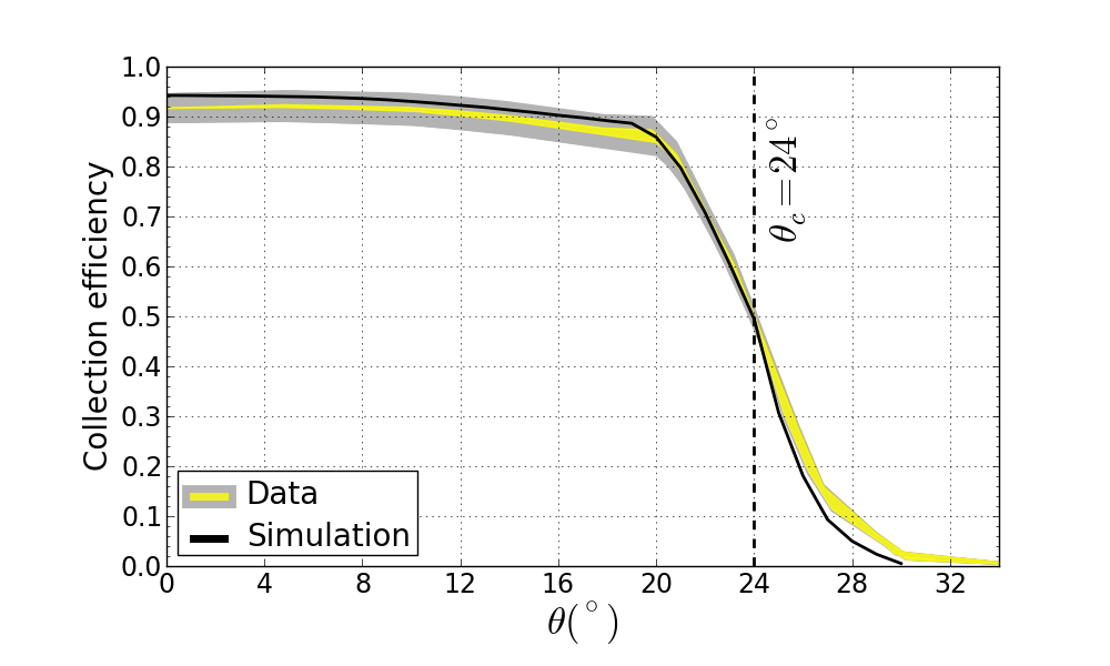
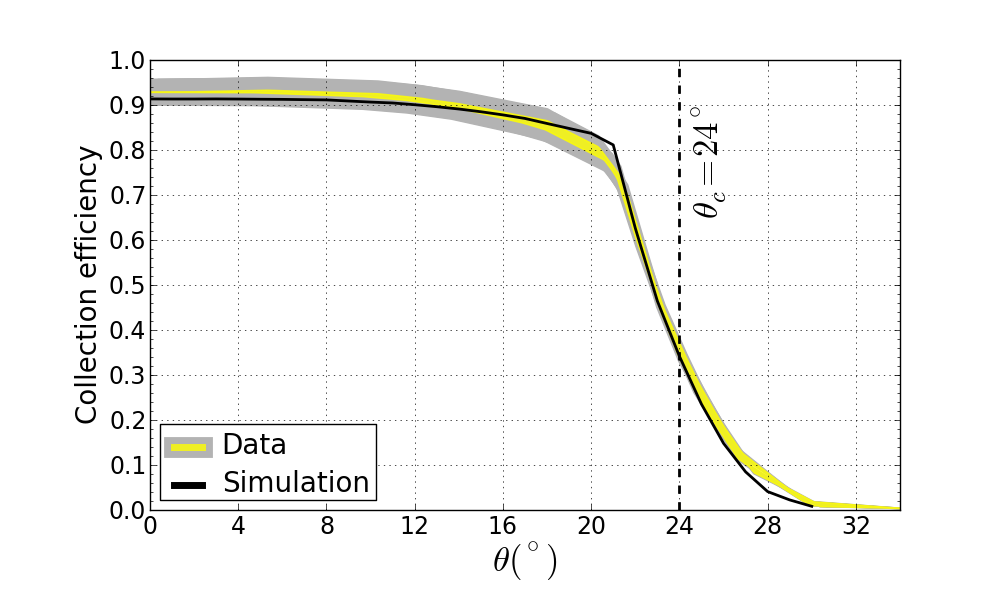
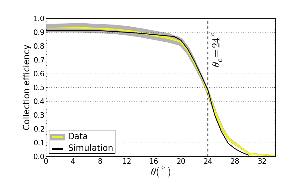
Figure 16 shows the collection efficiency for three different wavelengths and two azimuthal rotational directions (flat-to-flat and vertex-to-vertex). The top row shows the collection efficiency in the UV with a wavelength of 355 nm, the middle row shows measurements with a LED of 390 nm and the last row used a LED of 595 nm. The left column in Fig. 16 corresponds to the three measurements in the flat-to-flat configuration while the right column shows the three vertex-to-vertex measurements. On each plot the group of three measurements is represented by the yellow area indicating the range of variability of the measurements. The picoammeters666Keithley Picoammeter/Voltage Source 6487 used to measure the generated current from the photodiodes has an intrinsic accuracy that depends on the current level. This systematic uncertainty is indicated by the grey area. The black solid lines correspond to the simulation using Zemax for the each wavelength and rotation axis. As can be seen the collection efficiency reaches values 90% in the interesting angular region, especially for vertical incident angles ().
|
|
|
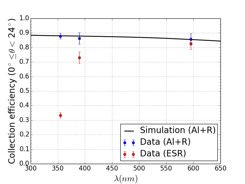
As pointed out in Sec. 3.2 it is important to have a high collection efficiency in the UV region since this is where the Cherenkov spectrum peaks. The measurements shown in Fig. 16 show that the selected coating performs very well in the interesting region of the Cherenkov spectrum. This is more clearly seen in Fig. 17. The averaged collection efficiency in the angular region of interest (0) is shown as a function of wavelength. The black solid line shows the results from simulation. As a comparison, the measurements performed on a light concentrator internally covered with the Vikuiti™ enhanced specular reflector (ESR) film from 3M7773M SA, Rschlikon, Switzerland. are also shown. As can be seen the ESR film performs well outside the UV regime but it has a low reflectivity in that wavelength range making it not a suitable solution for Cherenkov astronomy unless it is coated to enhance its reflectivity in the UV. On the contrary, our selected coating has the best collection efficiency in the UV light.
5 Conclusions
In this paper we showed the procedure used to design, optimize and manufacture a cost-effective light concentrator for Cherenkov astronomy. The selection of coating was driven by simulations and the final measured collection efficiency achieved a remarkable good agreement with the predictions from simulations. Furthermore, we showed that efficiencies of about 93% at normal incident angles are possible with this approach.
This work was focused on a light guide design suitable for the CTA single mirror small size telescopes with a camera consisting on SiPM as the active sensors. Nevertheless a similar optimized design can be adapted for larger size telescopes within the CTA project independently of the sensors (SiPM or the traditional photomultipliers) as well as for other projects working in the UV-light seeking to have an increased effective area of the camera such as fluorescence detectors used in cosmic-ray experiments.
Acknowledgments
We acknowledge the Swiss National Science Foundation and the University of Geneva for the received financial support as well as the Polish grants: 498/FNiTP/158/2011 from the Ministry of Science and Higher Education and UMO-2011/01/M/ST9/01891 from the National Science Centre for supporting the SST-1M project. We also acknowledge Mr. F. Jacocagni from TFP for his careful feedback and his precious collaboration on the coatings.
References
- [1] K. Bernlöhr et al., Astropart. Phys. 20 (2003) 111.
- [2] T.C. Weekes et al., Astropart. Phys. 17 (2002) 221.
- [3] B. Huber et al., Solid light concentrators for small-sized photosensors used in Cherenkov telescopes, in Proceedings of the 32nd International Cosmic Ray Conference (2011), Bejing, China.
- [4] H. Anderhub et al., JINST 8 (2013) P06008.
- [5] T. Bretz & M. Ribordy, Astropart. Phys. 45 (2013) 44.
- [6] E. Lorenz et al., The MAGIC telescope, status and future plans, AIP Conference Proceedings vol. 745, p. 622-627 (2005).
- [7] R. Winston et al., Nonimaging optics. ISBN: 0-12-759751-4, Elsevier Academic Press 2005.
- [8] CTA Consortium, Design Concepts for the Cherenkov Telescope, Experimental Astronomy, 32 (2011) 193 [arXiv:1008.3703v2].
- [9] J. Hinton et al., Astrop. Phys. 43 (2013) 1-356.
- [10] V. V. Vassiliev et al., Astropart. Phys. 28 (2007) 10.
- [11] A. Okumura, Astropart. Phys. 38 (2012) 18.
- [12] D. Renker & E. Lorenz, JINST 4 (2009) P04004; C. Piemonte, NIMA 568 (2006) 224.