A Geometrical-Based Throughput Bound Analysis
for
Device-to-Device Communications
in Cellular Networks
Abstract
Device-to-device (D2D) communications in cellular networks are promising technologies for improving network throughput, spectrum efficiency, and transmission delay. In this paper, we first introduce the concept of guard distance to explore a proper system model for enabling multiple concurrent D2D pairs in the same cell. Considering the Signal to Interference Ratio (SIR) requirements for both macro-cell and D2D communications, a geometrical method is proposed to obtain the guard distances from a D2D user equipment (DUE) to the base station (BS), to the transmitting cellular user equipment (CUE), and to other communicating D2D pairs, respectively, when the uplink resource is reused. By utilizing the guard distances, we then derive the bounds of the maximum throughput improvement provided by D2D communications in a cell. Extensive simulations are conducted to demonstrate the impact of different parameters on the optimal maximum throughput. We believe that the obtained results can provide useful guidelines for the deployment of future cellular networks with underlaying D2D communications.
Index Terms:
Device-to-device (D2D) communications, uplink reuse, throughput, guard distances, circle packingI Introduction
In recent years, device-to-device (D2D) communications underlaying a cellular infrastructure have received plenty of attention from both academia and industry. With D2D communications, a user equipment (UE) can directly exchange data with another one in its proximity, instead of having the base station (BS) as the relay node. By facilitating the reuse of cellular spectrum resources, D2D communications are promising in reducing transmission delay, increasing cell throughput, and enhancing spectrum efficiency. Thus, the D2D communications have been considered as one of the key components in the next-generation broadband cellular networks, such as the Third-Generation Partnership Project (3GPP) Long Term Evolution Advanced (LTE-A). Currently, the related work items are being standardized as LTE Direct in 3GPP as a Release 12 feature of LTE. Moreover, specific business models for different D2D usage cases are also being studied by wireless operators and vendors [1].
One of the serious challenges for D2D communications in cellular networks is the interference between D2D UEs (DUE) and other cellular UEs (CUE). When a pair of DUEs communicate using the uplink cellular resources, the D2D communication might be affected by the simultaneous transmission between a CUE and the BS. Moreover, if there are multiple concurrent D2D pairs, the accumulated interference may also influence the quality of the signal received by the BS. Similarly, when a D2D communication reuses the downlink resources, a transmitting DUE might cause reception failures of its nearby CUEs. It is still an open issue to effectively allocate the radio resources among DUEs and CUEs in cellular networks with underlaying D2D communications.
In this paper, we focus on an uplink resource reusing scenario, in which one CUE and multiple D2D pairs are transmitting simultaneously. We first investigate the guard distances from a DUE to the BS, to the transmitting CUE, and to other communicating D2D pairs, respectively. The basic ideas are: 1) a DUE receiver has to stay away with certain distances from the transmitting CUE and other DUE transmitters; and 2) all the DUE transmitters should keep a certain distance away from the BS, so that all the signal receptions can be successfully achieved. By utilizing the obtained guard distances, we then analyze the maximum number of concurrent D2D communications that can be carried within the observed cell, which is further used to study the influences of different parameters on the optimal throughput improvement.
The main contributions of this paper are twofold. First, we propose a geometrical method to arrange the concurrent D2D pairs in a cell to maximize the spectrum reuse, which is based on our analysis results of the interference-free guard distances. Second, we obtain the maximum throughput improvement of D2D communications in a single cell as a piecewise function of the distance between the transmitting CUE and the BS, which could be further used as a basis to design the radio resource allocation schemes for the UEs in a cellular network with underlaying D2D communications. To the best of our knowledge, this paper is one of the first to systematically study the throughput performance with multiple concurrent D2D pairs.
The remainder of the paper is organized as follows. In Section II, we summarize the related work in radio resource allocation and throughput analysis. The system model for our analysis is described in Section III. In Section IV, the closed-form expressions of the guard distances are obtained and followed by the derivation for the bounds of the maximum throughput improvement in a single cell. Simulation results are presented in Section V. A discussion about the possible future work is given in Section VI, and Section VII finally concludes this paper.
II Related Work
The idea of capturing the benefits of the proximity between network nodes has been studied to improve cellular network’s radio coverage [2], traffic balance [3], user fairness [4], and other performance metrics for quite a long time. However, these efforts usually assume that the local data exchanges utilize an unlicensed frequency band, such as the 2.4 GHz Industry Science Medicine (ISM) spectrum, rather than reusing the spectrum resources allocated for cellular networks. Given that the quality of service (QoS) in the unlicensed spectrum may fail to be controlled or guaranteed, the underlaying D2D communications are more preferable to both service providers and device vendors. Currently, there are multiple ongoing research topics in this area, including mode selection [5], scheduling [6], resource management [7], etc. A detailed survey of the design challenges and potential solutions for the D2D communications can be found in [8]. In this paper, we are interested in the effect of interference on throughput performance of the underlaying D2D networks. To control/coordinate the interference and improve the throughput performance, existing work can be roughly classified into two categories, including radio resource allocation and the theoretical analysis of the achievable performance bounds.
For the radio resource allocation, one of the important early work is [9], in which an initial framework for the D2D communications in the cellular networks was proposed. According to its simulation results, a D2D communication could be enabled without degrading the performance of the cellular network, even in an interference-limited scenario with heavy traffic load. In [10], by assuming that the radio resource managements were adopted for both the cellular and D2D connections, three possible resource allocation methods, i.e., non-orthogonal, orthogonal, and cellular operation, were studied. Moreover, two optimization cases, greedy sum-rate maximization and sum-rate maximization with rate constraints, were also analyzed in [10]. In [11], a radio resource allocation scheme was proposed for D2D communications underlaying cellular networks with fractional frequency. The different frequency bands utilized by DUEs and CUEs were chosen according to whether the UEs were located in the inner or outer region of a cell, so that the interference could be greatly alleviated. In one of the most recent work [12], under the power control constraint, the spatial distribution of a D2D network’s transmission power and the signal to interference plus noise ratio (SINR) were derived based on the homogeneous Poisson Point Processes (PPP). In general, most of the existing resource management schemes focused on the scenario that each cell had one D2D pair and one CUE (or multiple ones when directional antennas were applied at the BS) transmitting at the same time. The proper design guidelines to support multiple concurrent D2D pairs within one cell are still unclear for the radio resource allocation schemes.
For the theoretical analysis of the achievable performance bounds, available results are relatively fewer. In [13], the uplink capacity gain was derived when one D2D link was enabled in an FDD CDMA-based cellular cell. In [14], an interference-limited area (ILA) control scheme was proposed to manage the interference from CUEs to a D2D transaction when multiple antennas were used by the BS. By analyzing the coverage of ILA, a lower bound of the ergodic capacity was also obtained for DUEs using uplink cellular radio resources. After that, a similar approach was extended to the downlink resources sharing scenario in [15]. In [16], the maximum achievable transmission capacity, which was defined as the spatial density of successful transmissions per unit area, was analyzed for the hybrid D2D and cellular network through stochastic geometry. However, due to the inevitable interference accumulated at the BS, most of the existing analytical results assuming a single D2D pair in a cellular network cannot be directly extended to a scenario with multiple coexisting D2D pairs. Therefore, the performance of D2D communications in the latter is still an under-developed issue, which could further improve the spectrum efficiency and increase the cellular network throughput.
To make up the shortage of performance bounds analysis for D2D communications in cellular networks, some useful insights might be obtained from the existing results of the Protocol Interference Model (PrIM) and the Physical Interference Model (PhIM)-based capacity analyses, which were mainly initialized from [17]. By introducing a spatial protection margin , PrIM defines a location-based condition for successful communications between a single node pair. The condition could be applied to all the concurrent node pairs in the network to obtain the capacity bounds for different network settings, for example, the effect of directional antennas on network capacity bounds were studied in [18]. However, PrIM does not take into account the aggregated interference, which happens to be vital for the D2D scenario, e.g., the constraint on the total interference power accumulated at the BS. Comparing with PrIM, PhIM is based on the power capture model, and focuses on the aggregated interference on a specific receiver. By assuming the interference power follows a Gaussian distribution, the General PhIM was proposed in [19]. Moreover, a series of graph-based interference models have also been developed based on PhIM for different research purposes and network scenarios [20, 21]. However, the higher computation complexity, which is caused by calculating the sum of all the undesired signals, might also prevent the application of PhIM on large and complicated network scenarios, e.g., the D2D communications deployed in an irregular network area.
III System Model
In this paper, we aim to study the network throughput improvement when multiple D2D communications coexist with a single CUE-BS communication111This one CUE model presents the situation that orthogonal channel resources are allocated to different CUEs in traditional cellular networks such as GSM. The more general multiple CUEs scenario will be one of our future work items, which will be briefly discussed in Section VI.. To develop a tractable model of D2D communications in a single cell, it is assumed that the coverage area of a BS is a disk with radius . Two working modes, CUE and DUE, are available for each UE. In the CUE mode, a UE sends packets via the BS; while UEs in the DUE mode exchange packets via direct connections in an ad hoc style utilizing the uplink radio resource [22]. The case when the downlink radio resource is reused, which can still be analyzed by the method developed in this paper, will be one of our research issues in the near future.
To describe a signal’s power attenuation, a general path-loss model is applied here as
| (1) |
where is the transmission power, is the average received signal power at distance from the transmitter, is the path-loss constant determined by the hardware features of the transceivers, and is the path-loss exponent depending on the propagation environment [23]. For better readability, we use to represent the path-loss ratio of the transmission power at distance . Moreover, and are used to represent the different physical characteristics and constraints of CUE-BS and DUE-DUE links, respectively. This model can be extended to study the instantaneous throughput or throughput distribution by introducing a lognormal random variable representing the channel shadowing effect, which will be another topic of our future research.
Since a CUE’s transmission can always be coordinated by its BS, power control schemes could be implemented to achieve different design goals. For compensating the near-far effect , we assume that the average received signal power at a BS is controlled to the same level, , for each CUE [14]. Therefore, the maximum CUE transmission power is utilized when the CUE is located at the boundary of the cell, and .
Compared with the CUE-BS connection, the coordinations among D2D communications are usually limited, and are more vulnerable to the unexpected channel conditions. Thus, we assume that all the D2D communications are carried with a fixed transmission power and a constant bit rate . Moreover, we define that a D2D connection will only be established when the distance between the two DUEs is within a predefined range , where is a very short distance representing the minimum physical separation between any two UEs.
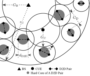
With multiple D2D pairs reusing the uplink resource in a cell, interference occurs between DUE and DUE, CUE and DUE, DUE and BS222Currently, the interference generated by the DUEs in the nearby cells is not considered. This approximation is reasonable as long as the frequency reuse factor is larger than one, which means neighboring cells are allocated with different uplink resources, so this kind of interference can be just ignored.. For successful receptions, we assume that two predefined Signal to Interference Ratio (SIR) thresholds should be achieved at a DUE as , and at the BS as , respectively. To guarantee , a DUE receiver should stay at a guard distance away from all the other transmitting DUEs, and at a guard distance away from the transmitting CUE to limit the received total interference. Similarly, to satisfy the required receiving SIR at the BS, there should also be a minimum guard distance between the BS and all the DUE transmitters, which limits the number of concurrent D2D pairs in a cell and the total interference accumulated at BS. In addition, considering that D2D communications are usually bidirectional (e.g., service discovery, data transmission, and ACK feedback) and the distance between a D2D pair is typically short, the transmitter and receiver of a D2D pair will not be distinguished in our interference analysis333This assumption could be verified by simulation, and the related results will be shown in Fig. 11, Section V-C.. Therefore, the Exclusive Region (ER) occupied by a D2D pair with link distance can be modeled as a disk with radius . Due to the possible difference of for each communicating pair, could be different for each ER. Moreover, we define and . For concurrent transmissions, two D2D pairs’ ERs should not overlap with each other. The three guard distances and ERs are depicted in Fig. 1, which demonstrates a part of a cell with the coexistence of of one CUE and several D2D pairs. For an ER, we use a grey disk to illustrate an imaginary hard core, whose diameter is the distance between the D2D pair. Since the boundary of a hard core represent all the possible relative positions of the D2D pair as long as is fixed, as shown in the figure, neither the BS guard region, which is a disk centered at the BS with radius , nor the CUE’s impact disk, which is a disk centered at the CUE with radius , could intersect with any D2D pair’s hard core. Moreover, all the hard cores have to stay inside the cell’s coverage area.
IV Theoretical Analysis
IV-A Parameter Setting for Guard Distances
Before investigating the bounds of the throughput improvement brought by the D2D communications in a single cell, the three guard distances , , and will be determined for a reasonable setting first in this subsection.
IV-A1 Calculations for
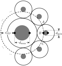
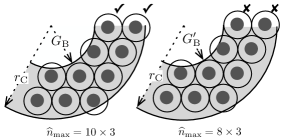
When no CUE is considered, for a DUE node, the worst interfered scenario happens when: a) its link distance reaches the maximum allowable value ; and b) it is affected by the maximum possible number of nearby D2D pairs. Owing to that is a fixed parameter for all the D2D pairs, the maximum number of ERs surrounding the observed D2D pair is obtained when holds for all the other D2D pairs, as shown in Fig. 2. With acceptable accuracy, only the surrounding D2D pairs in the first layer, which generate the majority part of the total interference, are considered here.
The number of the first layer surrounding D2D pairs could be calculated as
| (2) |
where the function in the denominator is used to calculate the length of the arcs in Fig. 2. The detailed expression of function is given in the Appendix. Since is the minimum distance between the interfered DUE and all the interferers, the transmission bit rate should be at least higher than the bit rate obtained in the worst interfered scenario, in which all the surrounding transmitters are located with distance to the observed DUE, as
| (3) |
where is the system bandwidth, and is the one-sided spectral density of additive white Gaussian noise (AWGN). Finally, could be calculated by combining with the path-loss model in (1) as
| (4) |
where and are the path-loss parameters associated with .
IV-A2 Calculations for
Based on the system model, no matter how many D2D pairs can be activated simultaneously, the effects of a CUE transmission’s interference on each communicating DUE node are independent of each other. Suppose a CUE node is located with distance to its BS, then its transmission power can be represented as
| (5) |
Similarly, considering the SIR constraint at DUE, we have
| (6) |
where is the distance between the CUE and the interfered DUE node. For a CUE, the worst case is that the being affected D2D pair has the longest link distance (), which should be used to determine for system setting. By combining the path-loss model in (1) and ignoring the small difference between the path-loss exponent of the CUE-BS and DUE-DUE links [14], could be obtained as
| (7) |
where is a function of the DUE transmission power as
| (8) |
IV-A3 Calculations for
For an observed BS, the worst interfered case happens when the number of D2D paris in its cell reaches the theoretical upper bound, which means: a) the CUE’s impact disk is fully included in the BS guard region, so it has no negative effect on any D2D communication; and b) the condition holds for each D2D pair, so each ER only occupies the smallest area. However, accurately calculating the maximum number of disks that could be arranged into a given ring area without intersection is still an open issue currently, which is known as a case of the circle/sphere packing problem in geometry [24].
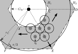
To solve the problem, two hexagons and are used to approximate the BS’s guard disk and the cell coverage area, respectively, as shown in Fig. 3. Then the ring area is transferred as the grey region consisting of six identical isosceles trapezoids with base angles. The side length of hexagon is set to , which means that the hexagon is circumscribed with the guard disk of BS, so the SIR requirement can still be achieved. For the hexagon , we let the six trapezoids’ total area in Fig. 3 equal the ring area determined by and , so its side length has to satisfy:
| (9) |
Therefore,
| (10) |
Due to the symmetry feature, we can focus on one third of the approximated ring area initially, e.g., the polygon region in Fig. 3. According to the system model, the most compact way to arrange D2D pairs is to locate the first ER’s center on line segment , while node is on the boundary of the ER’s hard core, and arrange other D2D ERs without overlapping along three directions , , and , as shown in the figure444The arrangement could also be made along directions , , and (from the cell boundary to the inside). For a network area large enough, these two arrangements lead to almost identical results, so we only consider the previous arranging method in this paper.. Note that, this arrangement is identical to the hexagon packing, which is the densest packing possible on a flat surface [24]. In this way, the maximum layers of D2D ERs that could be arranged in a trapezoid area can be calculated as
| (11) |
According to the geometry, in the observed polygon region , the number of DUE ERs that could be placed in the -th layer can be calculated as
| (12) |
where ,
| (13) |
represents the number of the ERs in the -th layer that could be arranged within the trapezoid , excluding the ones on the boundary , and
| (14) |
represents the number of the ERs in the -th layer that could be arranged within the trapezoid , including the ones on the boundary . Note that, when ERs are arranged near the two side boundaries of the observed polygon region ( and ), if more than half an ER’s hard core could be arranged within the boundary, the ER should be counted on one side only. Then the double counting errors will not happen. Therefore, the maximum number of ERs that could be arranged in the ring area determined by and can be approximated as follows
| (15) |
Once is obtained, the total interference generated by D2D communications accumulating at the BS can be calculated as
| (16) |
where and represent the corresponding distance between BS and the center of the -th ER in the -th layer within , and the center of the -th ER in the -th layer within , respectively, which are used to approximate the distance between BS and transmitting DUEs. Because , this approximation is acceptable. and could be calculated according to the Law of Cosine as follows
| (17) | |||||
| (18) |
where , , and .
Due to the SIR requirement, we also have
| (19) |
By combining equations (11)–(19) and the definition of , can be obtained in a numerical way (e.g., by the bisection search algorithm). Another byproduct here is that, when the CUE’s impact disk is fully covered by the BS guard region, the upper bound of the maximum throughput improvement could be calculated as
| (20) |
IV-B Bounds for Throughput Improvement in General Scenarios
It is clear that the actual capacity improvement is determined by the number of concurrent transmitting D2D pairs in the network. In a general scenario, the transmitting CUE’s impact disk could move out the guard region of the BS, so the total area for deploying non-overlapped D2D ERs is reduced, which may further affect the maximum throughput improvement in the cell. Due to the circular symmetry, a Cartesian coordinate system can be built with its origin at the observed BS, and the CUE’s impact disk can always be aligned with the -axis as shown in Fig. 4, where . According to the system model, the hard cores cannot intersect with neither the BS guard region nor cross the cell boundary, therefore, the actual area for deploying possible D2D ERs is a slightly larger ring region with inner radius and outer radius .
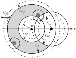
Recall that , so it is possible that the CUE’s impact disk might cross both the boundaries of BS guard region and the cell coverage area, which is called double-crossing here. When is relatively small, the length of the CUE’s impact disk’s diameter may still be shorter than when the impact disk is just to move out the cell’s coverage area, which means the double-crossing never happens. Therefore, the range of for no double-crossing could be written as , where could be derived by the critical condition mentioned above as
| (21) |
When , if is still shorter than given the CUE is on the boundary of the BS’s guard region, the double-crossing will only happen for a specific range of , and the CUE’s impact disk will not intersect with the BS’s guard region anymore. Therefore, the second threshold for can be obtained as
| (22) |
Finally, when , once the double-crossing happens, it will last until . Based on these analyses, the area for deploying D2D ERs could be obtained as a piece-wise function shown as below.
1) When :
-
•
If , the area for deploying the D2D ERs can be calculated as
(23) -
•
If , the CUE’s impact disk crosses the boundary of BS’s guard region,
(24) where as shown in Fig. 4, and the function given in the Appendix is used to calculate the area of two disks’ overlapping region.
-
•
If , the CUE’s impact disk is fully included in the ring area, therefore,
(25) -
•
If , part of the CUE’s impact disk moves out of the cell area, therefore,
(26)
2) When :
-
•
If , .
-
•
If , the CUE’s impact disk overlaps with the BS’s guard region, but the double-crossing does not happen,
(27) -
•
If , double-crossing happens,
(28) -
•
If , the CUE’s impact disk only overlaps with the ring area, therefore,
(29)
3) When :
-
•
If , .
-
•
If , the CUE’s impact disk only overlaps the BS’s guard region and the double-crossing does not happen, therefore,
(30) -
•
If , double-crossing happens,
(31)
As mentioned earlier, when all the ERs have identical radius , the most compact arrangement of all the ERs is the hexagon packing, in which each ER occupies a hexagon region with area . Therefore, the maximum number of concurrent D2D pairs that could be arranged within a single cell, when and are given, can be approximated by
| (32) |
Note that has two extreme situations ( and as defined earlier), which are corresponding to the minimum and maximum area an ER could cover, respectively. Therefore, for the general scenario, we could obtain the upper and lower bounds of the maximum throughput improvement in a cell as
| (33) |
and
| (34) |
V Performance Evaluation and Discussion
All our simulation results are obtained using MATLAB. While all the analytical results can be calculated directly, a simulator is also developed to investigate the expectations of the maximum throughput improvement when is changed to a random variable. The common parameters for the simulation are set as: cell radius m, minimum D2D communication range m, maximum D2D communication range m, system bandwidth MHz, and the one-sided spectral density of AWGN power dBm/Hz to represent a cell in the urban scenario. By referring to [25], the path-loss ratios are set as (dB) for the BS-CUE link, and (dB) for the DUE-DUE link, so the path-loss exponent . In the following part of this section, the simulation results are demonstrated in groups to show the effect of different parameters on the throughput improvement by D2D communications.
V-A Impact of on
Intuitively, increasing DUE’s transmission power could support higher bit rate with the same guard distance . However, the superposed interference at BS generated by DUEs also increases with . As a result, the guard distance is enlarged and the maximum number of concurrent D2D pairs in the observed cell is reduced. Therefore, for a given system setting, there should be an optimal range of to obtain a relatively good performance improvement.
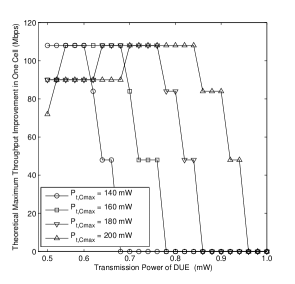
When the CUE’s impact disk is within the guard region of the BS, the upper bound for the maximum throughput of D2D communication could be obtained from (20), and the changing patterns of with different and are shown in Fig. 5. As demonstrated in this figure, when is relatively low, higher may lead to a lower maximum throughput improvement. This special phenomenon can be reproduced as shown in Fig. 6, which illustrates one third of the ring area determined by the same but slightly different BS guard distances, and explained as follow. When is fixed, the rise of will contribute to the increase of the total tolerable interference signal power at BS, which is represented as the decline of BS’s guard distance . However, since all the D2D pairs’ ERs have to be placed without overlapping while all the hard cores have to stay within the ring area, decreasing means fewer ERs could be arranged in the first inner layer of the ring area. Moreover, the increased area is accumulated at the outer ring, but the area will not be able to be utilized until one extra ER could be located in. Therefore, increasing may not directly result in the rise of .
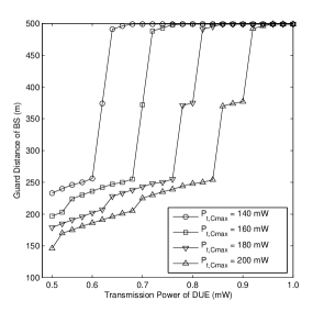
In addition to this interesting result, as we can see in Fig. 5, larger requires a higher and offers a wider varying range to obtain the optimal maximum throughput improvement. For example, when mW, the optimal range of is about mW. When mW, the optimal range of is changed to about mW. Moreover, if keeps growing after exceeding its optimal range, the total throughput improvement shrinks dramatically. This is because when all D2D pairs are constrained near the boundary of a cell area, a slight change in will cause a striking variation on both and the maximum number of concurrent D2D pairs. The relationship among , , and is also demonstrated in Fig. 7. As stated earlier, a higher leads to a shorter , before reaches to . Besides, the increase of DUE transmission power leads to the increase of , which limits the total number of D2D pairs in a cell and the total interference at the BS. In particular, rises significantly after a specific value of , which matches the tendency shown in Fig. 5.
V-B Impact of on
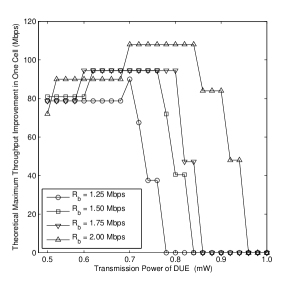
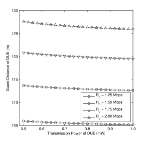
Similarly as the pervious evaluation group, Fig. 8 shows the upper bound for the maximum throughput of D2D communications varying with the changed DUE transmission power and the expected bit rate, when the CUE’s impact disk is fully included in the BS’s guard region. Generally, when is fixed, a higher bit rate requires a longer guard distance between DUE nodes, which is demonstrated in Fig. 9. The raise of increases the area of a D2D pair’s ER, but the total throughput could still be raised, even though the maximum number of concurrent communicating D2D pairs in the network is reduced. Similar to the previous group, when the DUE transmission power is monotonically increasing for a given , the throughput improvement grows to its optimal first, and then drops with a substantial amount. It is worth mentioning that the optimal maximum throughput improvement could be obtained with a range rather than one specific value of . This is due to that the number of maximum concurrent D2D pairs does not have a continuous linear relationship with other system parameters. Therefore, the changing of is shown as a step function. The effects of and on the DUE guard distance are illustrated in Fig. 9. It is clear that is slowly decreased while increases, which provides stronger support for satisfying the SIR requirement of DUEs. However, the major dominator for is in our simulation.
V-C Impact of on General Performance Bounds
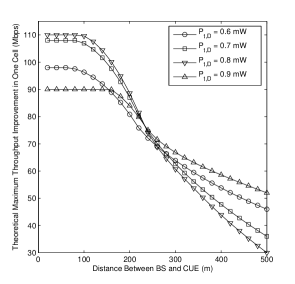
In a more general scenario, the CUE could appear in any location within its BS’s coverage area. As described in Section IV-B, since a CUE’s impact disk will impair some D2D pairs’ transmissions, the maximum throughput will be affected by , which is the distance between BS and the transmitting CUE. Based on (33), the general upper bound of the maximum throughput improvement is calculated, and shown in Fig. 10 to demonstrate its relationship with and .
It is clear that the upper bound of the maximum throughput is independent of at the very beginning, which represents the scenario that the CUE’s impact disk is fully included within BS’s guard region. Note that the length of the flat part of curves in Fig. 10 is proportional to . Since a higher indicates a larger as we discussed in the previous subsection, the CUE’s impact disk can still be incorporated within the BS’s guard region even with a larger . After that, the CUE’s impact disk starts to partially intersect with the ring area determined by and . Thus, the maximum number of D2D pairs shrinks, and so does the maximum throughput improvement. Compared with the results in Fig. 8, the simulation results for the maximum throughput in this figure are slightly higher, due to the different methods of determining the maximum number of D2D pairs in (15) and (32). However, the difference is merely the deviation about one or two D2D pairs, so it is still acceptable. Similar to Fig. 8, when the CUE’s effect is excluded, the maximum throughput improvement in a cell is developing as rises from 0.6 mW to 0.8 mW. But when is further increased to 0.9 mW, the maximum throughput falls to a relatively low level.
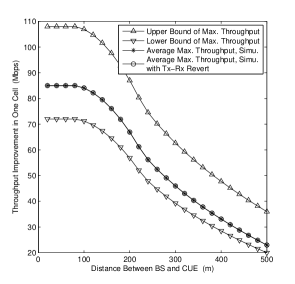
It should be noted that all the results above are obtained by setting . Therefore, the maximum number of D2D pairs in the network reaches its upper bound. When it comes to the other extreme scenarios i.e., , the obtained maximum throughput improvement turns out to be a lower bound. Both the upper and lower bounds of the maximum throughput improvement of a single cell are illustrated in Fig. 11. Moreover, the average maximum throughput, with identical system setting but variable for each D2D pair, is also obtained with different values of . As depicted in the figure, the curve for the average performance lies between the two bounds and closer to the lower bound. Currently, the probability distribution of is unknown, which is usually determined by the different application and user scenarios, so we could not provide a closed-form expression of the average maximum throughput improvement, but this will be addressed in our follow-on work. Besides, the simulation results obtained by rotating each DUE’s role between transmitter and receiver are also shown in Fig. 11. It is clear that there is no obvious difference between the rotated and non-rotated results. This verifies the assumption that, the transmitter and receiver of a D2D pair could be treated indiscriminately in our analysis, which was mentioned in Section III.
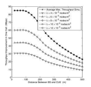
Considering that the number and locations of UEs in a cell may statistically follow certain distributions, we also simulated the throughput improvement of D2D communications in a cell when the network nodes are distributed by following the Poisson Point Process (PPP) with varied density , which is increased from to nodes/m2. As shown in Fig. 12, for different , the general pattern that the total throughput improvement is decreased with increased still holds. When is relatively low, the effect of , which demonstrates the change of network area left for D2D communications, on the throughput improvement is not that obvious. This is because that, when all the UEs are sparsely deployed, a D2D communication can always be successfully finished with high probability, as long as the distance between the DUE transmitter and receiver is within the predefined interval . On the other hand, when the density is larger than a threshold (e.g., when and nodes/m2), the number of concurrent D2D pairs in the network (and also the throughput improvement) is then constrained by the area possible for arranging D2D ERs, which means the changing of node density or distribution will not affect the performance anymore. As shown in the figure, for network scenarios with high PPP density, the maximum throughput improvement is almost identical to the average results illustrated in Fig. 11, in which all the network nodes are uniformly distributed with a high density. Therefore, for a given network setting, there should always be a optimal range of network density to establish D2D communications more efficiently.
VI Further Discussions
It is clear that the model and analyses mentioned above are only focusing on a single cell with uplink resource reusing between one CUE and multiple DUEs. However, the general method developed in this paper could be extended to a series of more complicated but also important scenarios. Currently, we are working on the following topics, and have obtained some interesting results on them.
First, for more general network modeling, multiple CUEs should coexist in the uplink transmission scenario. Due to the fact that orthogonal channel resources are allocated to different CUEs, the DUEs reusing different uplink resource will not interfere with each other. Therefore, the multiple CUEs scenario is theoretically equivalent to the combination of multiple independent single-CUE scenarios. However, the dynamic channel allocation work for all DUEs becomes difficult, and directly influents the final network performance improvement. We will focus on this in the near future.
Second, for a large network with multiple cells, which shapes a hexagon grid, the two-hexagon-approximation used in calculating can be simplified to approximate the BS’s guard region only. Moreover, if each cell is further divided into several sectors to utilize more complicated resource reusing scheme, the only change in the analytical method is that the possible interference generated from the neighboring cells with the same resource should be considered. However, the symmetry feature in hexagon and the resource reusing pattern could greatly simplify the entire analyzing process.
Third, if the D2D communications reuse the downlink resources rather than the uplink ones discussed in this paper, the interfering target is changed to the CUE(s) in the cell, and the BS’s transmission may also generate considerable interference to all the DUE receivers. Therefore, the guard distance-based system model need to be rebuilt, but the questions can be solved similarly by starting from the simplified one CUE scenario, and evolved to more complicated scenarios later.
Last but not least, although the throughput bounds do demonstrate the extreme situations (e.g., all the ERs has the identical radius or ) for a communicating D2D pair, it will be even more useful if we could provide the probability distribution functions (or probability mass functions) of these performance metrics rather than some fixed values. However, for the generalized scenario, in which each D2D pair’s transmission distance is randomly selected, the total number of D2D pairs in the finite cell or network region will be extremely difficult to be obtained due to the packing problem and the boundary effect. Therefore, the commonly used discrete-style interference analysis method (i.e., obtaining each concurrent transmitter’s impact on the observed receiver individually, and adding them together), which is also used in this paper, may not able to be applied again. This will make the derivation for the performance metrics’ distribution function even more complicated. Interestingly, we recently found out that by borrowing ideas from physics, the effect generated by a point transmitter could be equalized to an area transmitter under some conditions and vice versa [26]. By this means, the accumulated interference could be obtained by an area integral, so the complicated packing issues could be successfully rounded, and we could have chances to obtain the desired distribution functions in a more concise and simple way.
VII Conclusions
In this paper, we have obtained the proper system settings in terms of guard distances for BS, CUE, and DUE to ensure that multiple D2D communications could be simultaneously carried with the traditional uplink transmission from a CUE to the BS. In addition, we have derived the performance bounds of the single cell’s maximum throughput improvement. Moreover, some discussions about the possible extensions based on the current work are also given. We believe this work will provide some useful insights for the design and optimization of more efficient D2D communications in cellular networks.
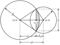
As shown in Fig. 13, two circles with radius and are centered at and , intersecting in a lens shaped region. The intersection points’ abscissa can be calculated as
| (35) |
and the length of the arc in the shaded region could be calculated as
| (36) |
The area of the shaded region, which is determined by and , can be calculated as
| (37) |
Similarly, the area of the other half asymmetric lens can be represented as . Therefore, the intersected area can be calculated as
| (38) | |||||
For a more general case, can be represented as below.
| (39) |
References
- [1] L. Lei, Z. Zhong, C. Lin, and X. Shen, “Operator controlled device-to-device communications in LTE-Advanced networks,” IEEE Commun. Mag., vol. 19, no. 3, pp. 96–104, 2012.
- [2] G. Neonakis Aggelou and R. Tafazolli, “On the relaying capability of next-generation GSM cellular networks,” IEEE Personal Commun. Mag., vol. 8, no. 1, pp. 40–47, 2001.
- [3] H. Wu, C. Qiao, S. De, and O. Tonguz, “Integrated cellular and ad hoc relaying systems: iCAR,” IEEE J. Sel. Areas Commun., vol. 19, no. 10, pp. 2105–2115, 2001.
- [4] H. Luo, R. Ramjee, R. Ramjee, P. Sinha, L. Li, and S. Lu, “UCAN: A unified cellular and ad-hoc network architecture,” in Proc. of ACM Mobicom, 2003, pp. 353–367.
- [5] H. Min, W. Seo, J. Lee, S. Park, and D. Hong, “Reliability improvement using receive mode selection in the device-to-device uplink period underlaying cellular networks,” IEEE Trans. Wireless Commun., vol. 10, no. 2, pp. 413–418, 2011.
- [6] M.-H. Han, B.-G. Kim, and J.-W. Lee, “Subchannel and transmission mode scheduling for D2D communication in OFDMA networks,” in Proc. of IEEE VTC (Fall), 2012, pp. 1–5.
- [7] D. H. Lee, K. W. Choi, W. S. Jeon, and D. G. Jeong, “Resource allocation scheme for device-to-device communication for maximizing spatial reuse,” in Proc. of IEEE WCNC, 2013, pp. 1–5.
- [8] G. Fodor, E. Dahlman, G. Mildh, S. Parkvall, N. Reider, G. Mikl¬ós, and Z. Tur¬ányi, “Design aspects of network assisted device-to-device communications,” IEEE Commun. Mag., vol. 50, no. 3, pp. 170–177, 2012.
- [9] P. Jänis, C.-H. Yu, K. Doppler, C. Ribeiro, C. Wijting, K. Hugl, O. Tirkkonen, and V. Koivunen, “Device-to-device communication underlaying cellular communications systems,” Int’l J. of Communications, Network and System Sciences, vol. 2, no. 3, pp. 169–178, 2009.
- [10] C.-H. Yu, K. Doppler, C. B. Ribeiro, and O. Tirkkonen, “Resource sharing optimization for device-to-device communication underlaying cellular networks,” IEEE Trans. Wireless Commun., vol. 10, no. 8, pp. 2752–2763, 2011.
- [11] H. S. Chae, J. Gu, B.-G. Choi, and M. Chung, “Radio resource allocation scheme for device-to-device communication in cellular networks using fractional frequency reuse,” in Proc. of IEEE APCC, 2011, pp. 58–62.
- [12] M. Erturk, S. Mukherjee, H. Ishii, and H. Arslan, “Distributions of transmit power and SINR in device-to-device networks,” IEEE Commun. Lett., vol. 17, no. 2, pp. 273–276, 2013.
- [13] Y. Cheng, H. Han, and X. Lin, “Device-to-device communication in CDMA-based cellular systems - uplink capacity analysis,” in Proc. of IEEE Communication Software and Networks, 2011, pp. 430–434.
- [14] H. Min, J. Lee, S. Park, and D. Hong, “Capacity enhancement using an interference limited area for device-to-device uplink underlaying cellular networks,” IEEE Trans. Wireless Commun., vol. 10, no. 12, pp. 3995–4000, 2011.
- [15] R. Chen, X. Liao, S. Zhu, and Z. Liang, “Capacity analysis of device-to-device resource reusing modes for cellular networks,” in Proc. of IEEE ComNetSat, 2012, pp. 64–68.
- [16] Z. Liu, T. Peng, Q. Lu, and W. Wang, “Transmission capacity of D2D communication under heterogeneous networks with dual bands,” in Proc. of IEEE CROWNCOM, 2012, pp. 169–174.
- [17] P. Gupta and P. R. Kumar, “The capacity of wireless networks,” IEEE Trans. Inf. Theory, vol. 46, no. 2, pp. 388–404, 2000.
- [18] S. Yi, Y. Pei, and S. Kalyanaraman, “On the capacity improvement of ad hoc wireless networks using directional antennas,” in Proc. of 4th ACM International Symp. Mobile Ad Hoc Netw. Comput., 2003, pp. 108–116.
- [19] A. Agarwal and P. R. Kumar, “Capacity bounds for ad hoc and hybrid wireless networks,” ACM SIGCOMM Comput. Commun. Rev., vol. 34, no. 3, pp. 71–78, 2004.
- [20] G. Brar, D. M. Blough, and P. Santi, “Computationally efficient scheduling with the physical interference model for throughput improvement in wireless mesh networks,” in Proc. of ACM Mobicom, 2006, pp. 2–13.
- [21] G. Kim, Q. Li, and R. Negi, “A graph-based algorithm for scheduling with sum-interference in wireless networks,” in Proc. of IEEE GLOBECOM, 2007, pp. 5059–5063.
- [22] K. Doppler, M. Rinne, C. Wijting, C. Ribeiro, and K. Hugl, “Device-to-device communication as an underlay to LTE-Advanced networks,” IEEE Commun. Mag., vol. 47, no. 12, pp. 42–49, 2009.
- [23] T. Rappaport, Wireless Communications: Principles and Practice. Prentice Hall, 2001.
- [24] K. Stephenson, “Circle packing: a mathematical tale,” Notices Amer. Math. Soc, vol. 50, pp. 1376–1388, 2003.
- [25] “Evolved Universal Terrestrial Radio Access (E-UTRA); Radio Frequency (RF) Requirements for LTE Pico Node B,” 3GPP, Tech. Rep. 36.931 Version 11.0.0 Release 11, 2012.
- [26] M. Ni, J. Pan, and L. Cai, “Power emission density-based interference analysis for random wireless networks,” Accepted by IEEE ICC 2014.