Current-induced spin torque resonance of magnetic insulators
Abstract
We formulate a theory of the AC spin Hall magnetoresistance (SMR) in a bilayer system consisting of a magnetic insulator such as yttrium iron garnet (YIG) and a heavy metal such as platinum (Pt). We derive expressions for the DC voltage generation based on the drift-diffusion spin model and quantum mechanical boundary condition at the interface that reveal a spin torque ferromagnetic resonance (ST-FMR). We predict that ST-FMR experiments will reveal valuable information on the current-induced magnetization dynamics of magnetic insulators and AC spin Hall effect.
Ferrimagnetic insulators such as yttrium iron garnet (YIG) with high critical temperatures and very low magnetization damping have been known for decades to be choice materials for in optical, microwave or data storage technologies Wu . Near-dissipationless propagation of spin waves make YIG wires and circuits interesting for low power data transmission and logic devices. A crucial breakthrough was the discovery that the magnetization in YIG can be excited electrically by Pt contacts Kajiwara , thereby creating an interface between electronic/spintronic and magnonic circuits. However, the generation of coherent spin waves by the current-induced spin orbit torques in Pt is a strongly non-linear process and the low critical threshold currents found by the experiments Kajiwara cannot yet be explained by theory Xiao . Here we suggest and model a simpler method to get to grips with the important current-magnetization interaction in the YIGPt system without a problematic threshold, viz. by employing the recently discovered magnetoresistance of YIGPt bilayers or Spin Hall Magnetoresistance (SMR) Nakayama ; Chen to detect current-induced spin torque ferromagnetic resonance (ST-FMR).
The SMR is the dependence of the electrical resistance of the normal metal on the magnetization angle of a proximity insulator and is caused by a concerted action of the Spin Hall Effect (SHE) review12 and its inverse (ISHE). An alternative mechanism of the SMR phenomenology in terms of an equilibrium proximity magnetization close to the YIG interface has been proposed Chen . However, this interpretation has been challenged by experiments Nakayama ; Althammer . Moreover, while experiments of many groups are described quantitatively well by the SMR model with one set of parameters Vlietstra ; Hahn1 ; VlietstraX ; Isasa ; Marmion , we are not aware of a transport theory that explains the observed magnetoresistance in terms of a monolayer-order magnetic Pt.
Current-induced spin torque ferromagnetic resonance (ST-FMR) has been demonstrated Liu ; Kondou ; Ganguly in bilayer thin films made from metallic ferromagnets (FM) and nonmagnetic metals (N). In these experiments the SHE transforms an in-plane alternating current (AC) into an oscillating transverse spin current. The resultant spin transfer resonates with the magnetization at the FMR frequency. The effects induced simultaneously by the Oersted field can be distinguished by a different symmetry of the resonance on detuning. The magnetization dynamics leads to a time dependence of the bilayer resistance by the anisotropic magnetoresistance (AMR). Mixing the applied current and the oscillating resistance generates a DC voltage that is referred to as spin torque diode effect Tulapurkar ; Sankey .
The longitudinal spin Seebeck effect was found to be frequency independent up to 30 MHz Roschewsky . The DC ISHE induced by spin pumping has been observed by many groups, but detection of the AC spin Hall effect Jiao13 has only recently been reported in metallic structures Weiler0 ; Wei ; Hyde as well as in PtYIG under parametric microwave excitation Hahn2 . A DC voltage can be generated in PtYIG under FMR conditions by rectification of the AC spin Hall effect by means of the SMR, but this signal was found to be swamped by the DC spin Hall effect Iguchi . A study of the spin Hall impedance concludes that the material constants of PtYIG bilayers do not depend on frequency up to 4 GHz Lotze .
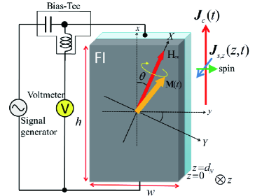
In this paper we suggest to combine the principles sketched above to realize ST-FMR for bilayers of a ferro- or ferrimagnetic insulator (FI) such as YIG and a normal metal with spin orbit interaction (N) such as platinum Mosendz10 (see Fig. 1). We derive the magnetization dynamics and DC voltages generated by the SMR-induced spin torque diode effect as a function of the external magnetic field. Our theory should help to better understand the elusive current-induced magnetization dynamics of ferromagnetic insulators which should pave the way for low-power devices based on magnetic insulators Wu .
The spin current through an FN interface is governed by the complex spin-mixing conductance Brataas00 . The prediction of a large for interfaces between YIG and simple metals by first-principle calculations Jia11 has been confirmed by recent experiments Burrowes12 ; Weiler . The spin transport in N (spin Hall system) can be treated by spin-diffusion theory with quantum mechanical boundary conditions at the interface to the insulating ferromagnet Chen ; Chiba . The AC current with frequency induces a spin accumulation distribution in N that obeys the spin-diffusion equation
| (1) |
where is the charge diffusion constant and spin-flip relaxation time in N. In position-frequency space the solution for the spatiotemporal dependence of the spin accumulation reads , where , is the spin-diffusion length, and the constant column vectors and are determined by the boundary conditions for the spin current density in the -direction , where is the spin polarization vector, which is continuous at the interface to the ferromagnet at and vanishes at the vacuum interface at . For planar interfaces
| (2) |
where is the spin Hall angle, the electrical conductivity, and the currents not accounting for spin-orbit interaction. and, where with
| (3) | |||
| (4) |
where is the unit vector along the FI magnetization and the complex spin-mixing interface conductance per unit area of the FIN interface. The imaginary part can be interpreted as an effective exchange field acting on the spin accumulation, which is usually much smaller than the real part. A positive Jia11 ; VlietstraX corresponds here to up-spins flowing from FI into N. For Pt(Ta) at the FMR frequency GHz with ps, indicating that the condition is fulfilled for these metals Jiao13 . In this limit the frequency dependence of the spin diffusion length may be disregarded such that
| (5) |
| (6) |
where with and . The ISHE drives a charge current in the - plane by the diffusion spin current along . The total charge current density reads
| (7) |
The averaged current density over the film thickness is with
| (8) | ||||
| (9) | ||||
where and are SMR rectification and spin pumping-induced charge currents, is the resistivity of the bulk normal metal layer and we recognize the conventional DC SMR with and , where
| (10) |
are effective resistivities that do not depend on frequency Chen .
ST-FMR experiments employ the AC impedance of the oscillating transverse spin Hall current caused by the induced magnetization dynamics that is described by the Landau-Lifshitz-Gilbert (LLG) equation, including the transverse spin current Eq. (6),
| (11) |
where with an external magnetic field and the sum of the AC current-induced Oersted field and the (thin film limit of) the dynamic demagnetization . , , and are the gyromagnetic ratio, the Gilbert damping constant of the isolated film, the saturation magnetization, and the thickness of the FI film, respectively.
We henceforth disregard the very low in-plane magnetocrystalline anisotropy field of Oe reported Vlietstra . The external magnetic field is applied at a polar angle in the - plane. It is convenient to consider the magnetization dynamics in the -coordinate system (Fig. 1) in which the magnetization is stabilized along the -axis by a sufficiently strong external magnetic field. Denoting the transformation matrix as , the magnetization precesses around the -axis, where as shown in Fig. 1. and are the static and the dynamic components of the magnetization, respectively. The LLG equation in the -system then becomes where the effective magnetic field in the -system is with , and with
| (12) |
a modulated damping and g-factor with . For a small-angle precession around the equilibrium direction , . Disregarding higher orders in in the -transformed LLG equation we arrive at the (Kittel) relation between AC current frequency and resonant magnetic field .
A DC voltage is generated by two different mechanisms, viz. the time-dependent oscillations of the SMR in N (spin torque diode effect) and the ISHE generated by spin pumping. This is quite analogous to electrically detected FMR in which the magnetization is driven by microwaves in cavities or coplanar wave guides. In metallic bilayers, the spin pumping signal due to the ISHE can be separated from effects of the magnetoresistance of the metallic ferromagnet by sample design and angular dependences Bai ; Obstbaum . Here we focus on the current-induced magnetization dynamics that induces down-converted DC and second harmonic components in the normal metal. Indicating time-average by the open-circuit DC voltage is where . The SMR rectification and spin pumping induced DC voltage are
| (13) | ||||
| (14) |
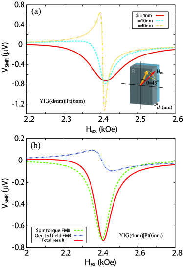
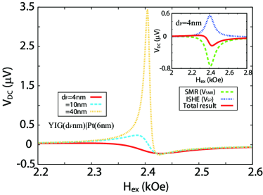
where and with , , the line width, the Oersted field from the AC current determined by Ampère’s Law (in the limit of an extended film), and speed of light. Using the material parameters for YIG Kajiwara and Pt Weiler ; Obstbaum shown in Tables 1 and 2 we compute the DC voltages in Eqs. (13) and (14). The calculated is plotted in Fig. 2 as a function of an external magnetic field and for different , resolved in terms of the contributions to the FMR caused by the spin transfer torque (symmetric) and the Oersted magnetic field (asymmetric). In Fig. 3 we show the total DC voltage with both spin torque diode and spin pumping contributions. The DC voltage in FPt bilayers depends more sensitively on for than because spin pumping is more important when the Gilbert damping is small. ST-FMR measurements are carried out at relatively high current density, so Joule heating in Pt may cause observable effects, the most notable being the spin Seebeck effect (SSE), which adds a constant background DC voltage to the SMR rectification signal Michael14 .
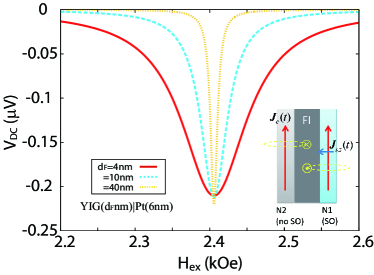
The ST-FMR spectra in Fig. 3 are enhanced for thicker F layers, but these are dominated by the Oersted field actuation. These less-interesting contributions can be eliminated in a tri-layer structure as in Fig. 4 in which the magnetic insulator is sandwiched by two normal metal films with the same electric impedance. The second film N2 should be Cu or another metal with negligible spin-orbit interaction and thereby contributions to the ST-FMR, the quality of the YIGN2 interface is therefore less of an issue. In Fig. 4 we plot pure ST-FMR signals obtained by setting in Eqs. (13) and (14), which may now be observed also for thick magnetic layers.
In summary, we predict observable AC current-driven ST-FMR in bilayer systems consisting of a ferromagnetic insulator such as YIG and a normal metal with spin-orbit interaction such as Pt. Our main results are the DC voltages caused by an AC current as a function of in-plane external magnetic field and film thickness of a magnetic insulator. The DC voltages generated in YIGPt bilayers depend sensitively on the ferromagnet layer thickness because of the small bulk Gilbert damping. The predictions can be tested experimentally by ST-FMR-like experiments with a magnetic insulator that would yield important insights into the nature of the conduction electron spin-magnon exchange interaction and current-induced spin wave excitations at the interface of metals and magnetic insulators.
This work was supported by KAKENHI (Grants-in-Aid for Scientific Research) Nos. 22540346, 25247056, 25220910, and 268063, FOM (Stichting voor Fundamenteel Onderzoek der Materie), the ICC-IMR, the EU-RTN Spinicur, EU-FET grant InSpin 612759, and DFG Priority Programme 1538 “Spin-Caloric Transport” (Grant No. BA 2954/1).
References
- (1) Recent Advances in Magnetic Insulators - From Spintronics to Microwave Applications, edited by M. Wu and A. Hoffmann, Solid State Physics 64 (Academic Press, 2013).
- (2) Y. Kajiwara, K. Harii, S. Takahashi, J. Ohe, K. Uchida, M. Mizuguchi, H. Umezawa, H. Kawai, K. Ando, K. Takanashi, S. Maekawa, and E. Saitoh, Transmission of electrical signals by spin-wave interconversion in a magnetic insulator, Nature 464, 262 (2010).
- (3) Y. Zhou, H. J. Jiao, Y.-T. Chen, G. E. W. Bauer, and J. Xiao, Current-induced spin-wave excitation in Pt/YIG bilayer, Phys. Rev. B 88, 184403 (2013).
- (4) H. Nakayama, M. Althammer, Y.-T. Chen, K. Uchida, Y. Kajiwara, D. Kikuchi, T. Ohtani, S. Geprägs, M. Opel, S. Takahashi, R. Gross, G. E. W. Bauer, S. T. B. Goennenwein, and E. Saitoh, Spin Hall Magnetoresistance Induced by a Nonequilibrium Proximity Effect, Phys. Rev. Lett. 110, 206601 (2013).
- (5) Y.-T. Chen, S. Takahashi, H. Nakayama, M. Althammer, S. T. B. Goennenwein, E. Saitoh, and G. E. W. Bauer, Theory of spin Hall magnetoresistance, Phys. Rev. B 87, 144411 (2013).
- (6) S. R. Marmion, M. Ali, M. McLaren, D. A. Williams, and B. J. Hickey, Temperature dependence of spin Hall magnetoresistance in thin YIG/Pt films, Phys. Rev. B 89, 220404(R) (2014).
- (7) M. Althammer, S. Meyer, H. Nakayama, M. Schreier, S. Altmannshofer, M. Weiler, H. Huebl, S. Geprg̈s, M. Opel, R. Gross, D. Meier, C. Klew, T. Kuschel, J.-M. Schmalhors, G. Reiss, L. Shen, A. Gupta, Y.-T. Chen, G. E. W. Bauer, E. Saitoh, and S. T. B. Goennenwein, Quantitative study of the spin Hall magnetoresistance in ferromagnetic insulator/normal metal hybrids, Phys. Rev. B 87, 224401 (2013).
- (8) N. Vlietstra, J. Shan, V. Castel, B. J. van Wees, and J. Ben Youssef, Spin-Hall magnetoresistance in platinum on yttrium iron garnet: Dependence on platinum thickness and in-plane/out-of-plane magnetization, Phys. Rev. B 87, 184421 (2013).
- (9) C. Hahn, G. de Loubens, O. Klein, M. Viret, V. V. Naletov, and J. B. Youssef, Comparative measurements of inverse spin Hall effects and magnetoresistance in YIG/Pt and YIG/Ta, Phys. Rev. B 87, 174417 (2013).
- (10) N. Vlietstra, J. Shan, V. Castel, J. Ben Youssef, G. E. W. Bauer and B. J. van Wees, Exchange magnetic field torques in YIG/Pt bilayers observed by the spin-Hall magnetoresistance, Appl. Phys. Lett. 103 , 032401 (2013).
- (11) M. Isasa, A. B.-Pinto, F. Golmar, F. Sánchez, L. E. Hueso, J. Fontcuberta, and F. Casanova, Spin Hall magnetoresistance as a probe for surface magnetization, arXiv:1307.1267.
- (12) S. R. Marmion, M. Ali, M. McLaren, D. A. Williams, and B. J. Hickey, unpublished.
- (13) L. Liu, T. Moriyama, D. C. Ralph, and R. A. Buhrman, Spin-Torque Ferromagnetic Resonance Induced by the Spin Hall Effect, Phys. Rev. Lett. 106, 036601 (2011).
- (14) K. Kondou, H. Sukegawa, S. Mitani, K. Tsukagoshi, and S. Kasai, Evaluation of Spin Hall Angle and Spin Diffusion Length by Using Spin Current-Induced Ferromagnetic Resonance, Appl. Phys. Express 5, 073002 (2012).
- (15) A. Ganguly, K. Kondou, H. Sukegawa, S. Mitani, S. Kasai, Y. Niimi, Y. Otani, and A. Barman, Thickness dependence of spin torque ferromagnetic resonance in /Pt bilayer films, Appl. Phys. Lett. 104, 072405 (2014).
- (16) A. A. Tulapurkar, Y. Suzuki, A. Fukushima, H. Kubota, H. Maehara, K. Tsunekawa, D. D. Djayaprawira, N. Watanabe, and S. Yuasa, Spin-torque diode effect in magnetic tunnel junctions, Nature 438, 339 (2005).
- (17) J. C. Sankey, P. M. Braganca, A. G. F. Garcia, I. N. Krivorotov, R. A. Buhrman, and D. C. Ralph, Spin-Transfer-Driven Ferromagnetic Resonance of Individual Nanomagnets, Phys. Rev. Lett. 96, 227601 (2006).
- (18) N. Roschewsky, M. Schreier, A. Kamra, F. Schade, K. Ganzhorn, S. Meyer, H. Huebl, S. Geprägs, R. Gross, S. T. B. Goennenwein, Time resolved spin Seebeck effect experiments as a probe of magnon-phonon thermalization time, arXiv:1309.3986.
- (19) M. Weiler, J. M. Shaw, H. T. Nembach, and T. J. Silva, Phase-sensitive detection of spin pumping via the ac inverse spin Hall effect, arXiv:1401.6469.
- (20) D. Wei, M. Obstbaum, M. Ribow, C. H. Back, and G. Woltersdorf, Spin Hall voltages from a.c. and d.c. spin currents, Nature Commun. 5, 3768 (2013).
- (21) P. Hyde, Lihui Bai, D. M. J. Kumar, B. W. Southern, C.-M. Hu, S. Y. Huang, B. F. Miao, and C. L. Chien, Electrical detection of direct and alternating spin current injected from a ferromagnetic insulator into a ferromagnetic metal, Phys. Rev. B 89, 180404 (2014).
- (22) C. Hahn, G. de Loubens, M. Viret, O. Klein, V. V. Naletov, and J. B. Youssef, Detection of Microwave Spin Pumping Using the Inverse Spin Hall Effect, Phys. Rev. Lett. 111, 217204 (2013); (E) 112, 179901 (2014).
- (23) H. J. Jiao and G. E.W. Bauer, Spin Backflow and ac Voltage Generation by Spin Pumping and the Inverse Spin Hall Effect, Phys. Rev. Lett. 110, 217602 (2013).
- (24) R. Iguchi, K. Sato, D. Hirobe, S. Daimon, and E. Saitoh, Effect of spin Hall magnetoresistance on spin pumping measurements in insulating magnet/metal systems, Appl. Phys. Express 7, 013003 (2014).
- (25) J. Lotze, H. Hübl, R. Gross, and S. T. B. Gönnenwein, Spin Hall Magnetoimpedance, arXiv:1404.7432.
- (26) O. Mosendz, J. E. Pearson, F. Y. Fradin, G. E. W. Bauer, S. D. Bader, and A. Hoffmann, Quantifying Spin Hall Angles from Spin Pumping: Experiments and Theory, Phys. Rev. Lett. 104, 046601 (2010).
- (27) A. Brataas, Yu. V. Nazarov, and G. E. W. Bauer, Spin-transport in multi-terminal normal metal-ferromagnet systems with non-collinear magnetizations, Eur. Phys. J. B 22, 99 (2001).
- (28) X. Jia, K. Liu, K. Xia, and G. E. W. Bauer, Spin transfer torque on magnetic insulators, Europhys. Lett. 96, 17005 (2011).
- (29) C. Burrowes, B. Heinrich, B. Kardasz, E. A. Montoya, E. Girt, Y. Sun, Y. Y. Song, and M. Wu, Enhanced spin pumping at yttrium iron garnet/Au interfaces, Appl. Phys. Lett. 100, 092403 (2012).
- (30) M. Weiler, M. Althammer, M. Schreier, J. Lotze, M. Pernpeintner, S. Meyer, H. Huebl, R. Gross, A. Kamra, J. Xiao, Y.-T. Chen, H. Jiao, G.E.W. Bauer and S.T.B. Gönnenwein, Experimental Test of the Spin Mixing Interface Conductivity Concept, Phys. Rev. Lett. 111, 176601 (2013).
- (31) T. Chiba, G. E. W. Bauer, and S. Takahashi, Spin torque transistor revisited, Appl. Phys. Lett. 102, 192412 (2013).
- (32) L. Bai, P. Hyde, Y. S. Gui, and C.-M. Hu, V. Vlaminck, J. E. Pearson, S. D. Bader, and A. Hoffmann, Universal Method for Separating Spin Pumping from Spin Rectification Voltage of Ferromagnetic Resonance, Phys. Rev. Lett. 111, 217602 (2013).
- (33) M. Obstbaum, M. Härtinger, H. G. Bauer, T. Meier, F. Swientek, C. H. Back, and G. Woltersdorf, Inverse spin Hall effect in /normal-metal bilayers, Phys. Rev. B 89, 060407 (2014).
- (34) M. Schreier, G. E. W. Bauer, V. Vasyuchka, J. Flipse, K. Uchida, J. Lotze, V. Lauer, A. Chumak, A. Serga, S. Daimon, T. Kikkawa, E. Saitoh, B. J. van Wees, B. Hillebrands, R. Gross, S. T. B. Goennenwein, Sign of inverse spin Hall voltages generated by ferromagnetic resonance and temperature gradients in yttrium iron garnetplatinum bilayers, arXiv:1404.3490.