Sum-rate maximization of OFDMA femtocell networks that incorporates the QoS of macro mobile stations
Abstract
This paper proposes a power allocation scheme with co-channel allocation for a femto base station (BS) that maximizes the sum-rate of its own femto mobile stations (MSs) with a constraint that limits the degradation of quality of service (QoS) of macro MSs. We have found a closed-form solution for the upper limit on the transmission power of each sub-channel that satisfies the constraint in a probabilistic sense. The proposed scheme is practical since it uses only the information easily obtained by the femto BS. Moreover, our scheme meets the constraint with minimal degradation compared to the optimal sum-rate of the femto MSs achieved without the constraint.
I Introduction
Femtocell technology has recently attracted significant attention as a way to enhance the performance of wireless cellular systems for indoor areas [1, 2]. Because of their inherent low-power, short-range characteristics, a number of femto base stations (BSs) can be deployed within a macrocell to achieve a high degree of spatial reuse of the spectrum resources. Moreover, there is no cost associated with site acquisition and backhaul connectivity for femto BSs (F-BSs) because F-BSs are installed in customer premises that have broadband access.
When femtocells and macrocells share the same frequency resources, mutual interference, referred to as cross-tier interference, is present. In this study, we considered the situation in which a macro BS (M-BS) always transmits with the same power across sub-channels and does not change its operation after the introduction of the femtocells. Because the transmission power used by a M-BS is high compared to the low transmission power used by a F-BS, when the femtocell is located near the M-BS, the signal strength received by a femto mobile station (F-MS) from the M-BS is much stronger than that from the F-BS. In this case, different frequency resources should be allocated to the femtocell to avoid the severe interference caused by the M-BS [3]; this allocation is referred to as orthogonal channel allocation [4].
In practice, femtocells are more likely to be installed in outer regions of a macrocell to overcome the weak signal strength received by MSs from the M-BS in those areas. In those regions, the signal strength received by a M-MS from a F-BS is relatively strong given the poor performance of the M-MS. In this case, if the F-BS appropriately controls its transmit power, the femtocell and the macrocell can efficiently share the same frequency resources; this allocation is referred to as co-channel allocation [5]. In terms of area spectral efficiency [6], co-channel allocation has potential gains over orthogonal allocation due to the additional level of spatial reusability of frequency resources [7]. With co-channel allocation, we propose a power allocation algorithm for a F-BS that probabilistically limits the quality of service (QoS) degradation of M-MSs caused by the cross-tier interference from the F-BS. Notice here, central coordinating across the F-BS and the M-BS is another direction to pursue, which lies in the framework of coordinate multipoint (CoMP) [8, 9, 10]. However, we will not use the CoMP technique in this work.
In this study, we considered an orthogonal frequency division multiple access (OFDMA) system that is a basis for IEEE802.16e WiMAX [11] and 3GPP long-term evolution (LTE) [12]. In OFDMA systems, total bandwidth is divided into several sub-channels; hence, a F-BS can adjust the transmit power of each sub-channel to maximize its performance. The cross-tier interference problem for downlink OFDMA femto/macro two-tier networks has been investigated in our earlier work [13]. In that paper, we proposed a power allocation algorithm for the F-BS that maximizes the weighted sum-rate of F-MSs and M-MSs near the femtocell. In this one, we propose a power allocation algorithm for a F-BS that maximizes the sum-rate of the F-MSs while considering the QoS of each M-MS.
After describing the system model under consideration in Section II, we present the proposed femtocell power allocation scheme in Section III. Section IV evaluates the performance gains of the proposed scheme by simulation, and Section V concludes the paper.
II System Overview
We considered the situation in which only one F-BS provides significant interference to any M-MS; this is the case when F-BSs are sparsely distributed in space within the macrocell. To limit the degradation in QoS of the M-MS caused by the F-BS, the F-BS should know which sub-channel is used to serve the M-MS located in the vicinity of the femtocell, and the level of interference it could cause to the M-MS if it were to use the same sub-channel. We consider the case in which the F-BS periodically decodes the resource allocation information (RAI) transmitted by the M-BS; the RAI is transmitted in the MAP field of the downlink sub-frame in WiMAX [11] and the physical downlink control channel (PDCCH)) in LTE [14, 12]. Note that when the F-BS receives and decodes the RAI in a downlink sub-frame, the sub-frame must not be used by the F-BS to transmit data to its F-MSs. If the F-BS receives and decodes the RAI frequently, for example at every other frame, then the performance of the femtocell is degraded by 50%. On the other hand, if the interval between two readings of the RAI is too long, then the RAI is likely to be outdated. With an appropriate decoding interval, for instance once every ten frames, the femtocell can maintain 90% of its sum-rate; this degradation is acceptable to femtocells whose sum-rates are generally very high. In practice, stationary or slowly moving M-MSs are likely to be given the same sub-channel over the multiple frames when it has traffic to be downloaded from the M-BS since the channel conditions do not change quickly for those M-MSs. For example, with the center frequency of 2.5GHz, the coherence time of the channel for a MS which is moving 4km/h is 100msec, which corresponds to 100 sub-frames in LTE. Hence, the RAI is effective with the appropriate interval. If the M-BS changes its allocation of sub-channels, then the F-BS can track the allocation within half of the interval on average. In this study, we assumed that the resource allocation when the F-BS transmits is the same as that decoded in the RAI.
In order to identify the level of interference that the F-BS could cause M-MS , the F-BS needs to know the channel gain of sub-channel from the F-BS to M-MS , which we denote by . However, in practice, the gain cannot be obtained by the F-BS, since there is no direct feedback channel from the M-MS to the F-BS. Instead, the F-BS can obtain the average of the channel gain over all sub-channels denoted by through the wired backhaul, since M-MS reports the average received power from each adjacent BS to its serving M-BS for specific purposes, such as hand-over; in LTE, for example, the average received power is calculated from the primary and secondary synchronization signals (PSS and SSS) that are transmitted from each BS at every 5 msec [15]. A M-MS can differentiate the source of the received signal since each BS uses a unique scrambling code. Note that PSS and SSS are scrambled over the frequency range; hence, M-MS still cannot measure .
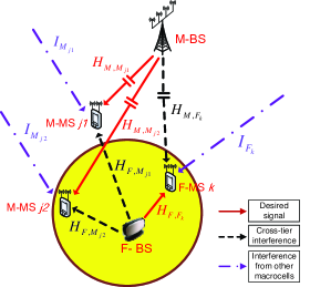
For simplicity, the building where the F-BS is installed is assumed to be circular, as represented in Fig. 1. With regard to the access policy of the femtocell, the closed policy is considered; hence, a M-MS can be located inside the building as well as outside. From the received signal strength of the uplink control signal from M-MSs, the F-BS can also determine whether a specific M-MS is inside or outside the building, given the additional attenuation caused by the wall. The wall-loss is defined as the ratio of the strength of the signal before penetrating the wall to that after penetrating the wall, and is denoted as . For fast-fading, we assume Rayleigh fading.
III Femtocell Power Allocation
III-A The Objective of a Femtocell
In this study, the objective of a femtocell is to maximize its sum-rate with an additional QoS constraint. The QoS constraint is defined as
| (1) |
where is the ratio of the SINR with the femtocell to that without the femtocell for the M-MS that uses sub-channel , is the desired limit for the QoS degradation, and is the allowable error that does not meet the limit. It is impossible for the F-BS to guarantee the absolute QoS of the M-MS, since the QoS of the M-MS could be below the required QoS even before the introduction of the femtocell. Instead, the F-BS limits the SINR degradation of the M-MS caused by the femtocell since a SINR is a major value to determine QoS. Moreover, because of fast fading, the QoS constraint should be expressed in a probabilistic sense. Note that each M-MS may have a different QoS requirement depending on its traffic type. In addition, for low SINR regions where F-BSs are normally installed, the ratio in rate is approximated as that in the SINR, since is approximated as .
With the QoS constraint, the objective of a femtocell is represented as
| (2) |
where is the transmit powers of the F-BS assigned to sub-channel , is the total transmit power, and is the number of sub-channels. The rate of F-MS that uses sub-channel , , is expressed as
| (3) |
where is the transmit powers of the M-BS assigned to sub-channel , is the noise variance, and and are the antenna gains of a F-BS and a M-BS, respectively. In the above equation, for sub-channel , the channel gain from the F-BS to F-MS , the channel gain from the M-BS to F-MS , and the interference from other M-BSs to F-MS are represented as , , and , respectively.
When M-MS located outside the building uses sub-channel , is further represented as
| (4) | |||||
where, for sub-channel , is the channel gain from the M-BS to M-MS and is the interference from other M-BSs to M-MS . Note that the approximation in the last row is valid, since is normally much larger than .
III-B The Power Limit on Each Sub-Channel
The power limit on each sub-channel is derived from the QoS constraint. In the derivation, is divided into two parts: for path loss and shadowing and for fast fading. Similarly, is divided into and . Note that and are the same across different sub-channels, respectively. The power limits are derived as
| (5) | |||||
where , , , and .
F-BSs can know from the uplink control signal of M-MS . Note that is not used for inside M-MSs. and are design parameters, and is a determined value. The only term that F-BS cannot know is . In the proposed scheme, we approximate to , the interference that the F-BS experiences from neighboring M-BSs, since the distance between the F-BS and M-MS is relatively very short compared to that between the neighboring M-MSs and the F-BS or M-MS . The approximation error could be large when the distance between the F-BS and M-MS is long. Fortunately, this is the case when the power limit is also very large. In other words, hardly approaches in that case.
III-C Optimization
The optimization (2) with the QoS constraint is a convex problem; therefore, the optimal solution can be found from the Karush-Kuhn-Tucker (KKT) condition [16] as follows. Let . Then, the Lagrangian is . From the KKT conditions, the optimal solution is found to be
| [see APPENDIX for details]. | (6) |
The above solution can be implemented as follows. First, the water-filling (WF) algorithm [17] is run, then the sub-channels that violate are checked. Next, for those sub-channels, are assigned and the total power is reduced by per each sub-channel. The above procedure is repeated for the remaining sub-channels with the reduced total power until there is no sub-channel that violates the upper limit.
IV Numerical Results
The Monte Carlo method was used to evaluate the performance of the proposed scheme in a case in which 50 M-MSs are randomly located anywhere in the macrocell including inside the building and 50 sub-channels are allocated in a round-robin way to the M-MSs. To calculate interference from neighboring M-BSs, we considered the adjacent 18 macrocells.
For the femtocell, without loss of generality, we randomly generated a F-MS inside the building and assume that it can access all 50 sub-channels. For path loss models, the IMT-Advanced Indoor Hotspot NLoS model and the Urban Micro NLoS model with hexagonal cell layout [18], with the center frequency of 2.5GHz, were used for the femtocell and the macrocells, respectively. The wall-loss is set as 3dB, which represents the case in which a building is enclosed by windows or thin walls [19]. We set , the radius of the building, to 30m and the radius of the macrocell to 500m. Antenna gains of a M-BS and a F-BS are set as 15dBi and 2dBi, respectively.
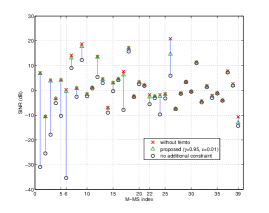
To more effectively represent the benefit of the proposed scheme, we depict the SINR values of M-MSs located inside in Fig. 2. To obtain the figure, we repeated the simulation 20 times; hence, 1,000 M-MS were generated. Indices from 1 to 6 represent the M-MSs located inside the building. Similarly, indices from 7 to 22 and from 23 to 39 correspond to the M-MS located between and and between and , respectively. Fig. 2 shows that the proposed scheme can maintain the SINRs of the M-MSs; however, without the QoS constraint, the introduction of the femtocell could severely degrade the performance of the M-MSs especially when the M-MSs are near the F-BS.
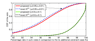
Even though the QoS constraint limits the degradation of M-MSs, the sum-rate of F-MSs becomes worse because the F-BS cannot optimally allocate its transmit power for the F-MSs with the constraint. The resulting degradation of the sum-rate of the F-MSs is shown in Fig. 3. The CDF shows that 10% of the F-MSs experience 8% or more degradation in their sum-rate with the tighter constraint. With a less tight constraint, only 5% of F-MSs experience 3% or more degradation. The degradation is not significant, especially when we consider the huge gain that the F-MSs achieve with the introduction of the femtocell [13]. Note that here we do not consider the degradation caused by periodic unavailability of the frames that are used for decoding the RAI. More than half of the M-MSs are located nearer to the M-BS than the F-BS; hence, the approximated value of and consequently that of for the M-MSs are higher than the exact ones. Since a higher leads to a less tight constraint on the transmit powers of each sub-channel, the sum-rate of the F-MSs increases whereas that of M-MSs decreases. Therefore, the proposed scheme is slightly better than the exact one in terms of the sum-rate of F-MSs.
V Conclusions
We have derived a closed-form solution of the upper limit on the transmission power of each sub-channel of a F-BS that guarantees the probabilistic QoS of M-MSs. With the upper limit, the proposed scheme can meet various QoS constraints of M-MSs even if the M-MSs are very close to the F-BS, which could be a disaster for those M-MSs without the proposed power limit. Moreover, compared to the case when a F-BS allocates its power to maximize only the sum-rate of its own F-MSs, the proposed scheme avoids significant degradation in the sum-rate while meeting the QoS constraint.
The KKT conditions are as follows:
| (7) | |||
| (8) | |||
| (9) | |||
| (10) |
Two cases follow from (9). For the first case , the third condition in (8) makes ; from (10), that equality leads to . Hence, For the second case , from the second condition in (8) and (10), . That is, If then ; thus, according to the third condition in (8). Consequently, . Conversely, if then assuming that ; hence, , which makes according to the third constraint in (8). Thus, the assumption is contradictory. Hence, when . Therefore, by incorporating both cases, we get .
References
- [1] Femtoforum, Interference management in UMTS femtocells, Dec. 2008, available at http://www.femtoforum.org.
- [2] V. Chandrasekhar, J. G. Andrews, and A. Gatherer, “Femtocell networks: a survey,” IEEE Commun. Magazine, vol. 46, no. 9, pp. 59–67, Sep. 2008.
- [3] I. Güvenç, M.-R. Jeong, F. Watanabe, and H. Inamura, “A hybrid frequency assignment for femtocells and coverage area analysis for co-channel operation,” IEEE Commun. Letters, vol. 12, no. 12, pp. 880–882, Dec. 2008.
- [4] V. Chandrasekhar and J. G. Andrews, “Spectrum allocation in tiered cellular networks,” IEEE Trans. Commun., vol. 57, no. 10, pp. 3059–3068, Oct. 2009.
- [5] V. Chandrasekhar, M. Kountouris, and J. G. Andrews, “Coverage in multi-antenna two-tier networks,” IEEE Trans. Wireless Commun., vol. 8, no. 10, pp. 5314–5327, Oct. 2009.
- [6] M. S. Alouini and A. J. Goldsmith, “Area spectral efficiency of cellular mobile radio systems,” IEEE Commun. Veh. Technol., vol. 48, no. 4, pp. 1047–1066, July 1999.
- [7] K. Sundaresan and S. Rangarajan, “Efficient resource management in OFDMA femto cells,” in Proc. ACM MOBIHOC, May 2009.
- [8] F. Sun and E. De Carvalho, “A Leakage-Based MMSE Beamforming Design for a MIMO Interference Channel,” IEEE Signal Processing Letters, vol. 19, no. 6, pp. 368–371, June 2012.
- [9] T. M. Kim, F. Sun, and A. Paulraj, “Low-Complexity MMSE Precoding for Coordinated Multipoint With Per-Antenna Power Constraint,” IEEE Signal Processing Letters, vol. 20, no. 4, pp. 395–398, April 2013.
- [10] F. Sun and E. De Carvalho, “Weighted MMSE Beamforming Design for Weighted Sum-Rate Maximization in Coordinated Multi-Cell MIMO Systems,” in 2012 IEEE Vehicular Technology Conference (VTC Fall), Sept 2012, pp. 1–5.
- [11] IEEE, 802.16e-2005 and 802.16/Cor1; IEEE Standard for Local and Metropolitan Area Networks, Part 16, Feb. 2006.
- [12] 3GPP TS 36.101 v9.2.0, Evolved Universal Terrestrial Radio Access (E-UTRA); User Equipment (UE) radio transmission and reception (Release 9), Dec. 2009.
- [13] M.-S. Kim, H. W. Je, and F. A. Tobagi, “Cross-tier interference mitigation for two-tier OFDMA femtocell networks with limited macrocell information,” June 2010, accepted to GLOBECOM 2010, available at http://www.stanford.edu/ minsung/MinsungGlobecomCameraReady.pdf.
- [14] F. Sun, M. Rahman, and D. Astely, “A Study of Precoding for LTE TDD Using Cell Specific Reference Signals,” in 2010 IEEE 71st Vehicular Technology Conference (VTC 2010-Spring), May 2010, pp. 1–6.
- [15] F. Sun, L. Lu, and T. Sorensen, “Designs of precoding for LTE TDD using cell specific reference signals,” in 2010 IEEE GLOBECOM Workshops (GC Wkshps), Dec 2010, pp. 871–875.
- [16] S. Boyd and L. Vandenberghe, Convex Optimization. Cambridge University Press, 2004.
- [17] T. M. Cover and J. A. Thomas, Elements of Information Theory. New York: Wiley, 1991.
- [18] Radio Communication Study Group, Guidelines for evaluation of radio interface technologies for IMT-Advanced, ITU 2nd meeting of working party 5D, Dubai, June-July 2008.
- [19] IEEE 802.11-10/0078r0, Supporting Document for Wall Penetration Loss, Jan. 2010.