Effect of boundary scattering on spin-hall effect
Abstract
The spin dependent reflection in quasi-two-dimensional electron gas from an impenetrable barrier in presence of Rashba and Dresselhaus spin-orbit coupling is analysed in detail. It is shown that the due to spin-orbit effects the reflected beam split in two beams gives rise to multiple reflection analogous to phenomenon birefringence. The interplay between Rashba and Dresselhaus spin orbit coupling gives rise to anisotropy in Fermi energy surface and a non-zero net spin-polarized current oscillating with two frequencies for all the values of incident angle except at when averaged over all components of reflected beam. It is also shown that in over critical region,all the three polarization components as well as net polarization has non-zero values and are exponentially decaying as distance from the barrier increases which in turns spin-accumulation near the barrier is an important consequence of spin-hall effect.
1 Introduction
The manipulation and coherent control of electronic spin degree of freedom has emerged as an important area of research in recent years. It in turn requires the ability to generate, inject and control spin polarized charge current - an example of that is Datta-Das spin-transistor Datta , where a semiconductor is sandwiched between two Ferromagnetic contacts. The injection and detection of spin polarized current is achieved by using Ferromagnetic contacts in which spin is easier to manipulate because it behaves as a collective degree of freedom. In the semiconductor region, coherent control of spin polarized current is done using the band structure spin-orbit(SO) coupling, known as Rashba SO interaction which arises due to structural inversion asymmetryRashba .
In recent years it has been realized that SO coupling can be used to efficiently generate and detect spin-polarized current in semiconductor heterostructure without the Ferromagnetic contactspareek . In finite size sample with SO coupling when an unpolarized charge currents passes it generates spin currents(via SO scattering) in transverse direction which in turn leads to spin accumulation at the lateral edges of the sample and is known as Spin -Hall effect(SHE)Kato ; Sih ; Wunderlich . The Spin accumulation due to SHE has been observed experimentallyDyakonov ; Hirsch ; Zhang ; Murakami ; Sinova . In such systems the spin accumulation and its relation to bulk spin current is a complex issue. This is because in finite size sample, the lateral edges of the sample acts like an impenetrable barrier for particles which carries spin. Therefore the boundary spin accumulation in such systems is affected by the elastic scattering of spin polarized carriers from the sample boundary in presence of SO coupling. More precisely, spin-dependent elastic reflection from an impenetrable barrier in the presence of SOC depends on the spin-orientation of particles which in-turn affects the spin accumulation. Hence spin accumulation at sample boundary not only depends on the bulk spin current but also on the spin-dependent scattering from the lateral impenetrable barrier. For system with only Rashba SO coupling. Spin-dependent elastic reflection of 2DEG from an impenetrable barrier in the presence of Rashba SOC was studied in Ref.winkler , where it was shown to generate spin polarized reflected beam.
The spin-orbit coupling owes its origin to appearance of inversion symmetry breaking electrical fields whether they arise intrinsically in the band structure(lack of inversion center) or by an external confining potential. In the former case inversion symmetry is broken locally and resulting SO interaction is known as Dresselhaus spin-orbit couplingDress , while in the later case confining potential leads to structure inversion asymmetry which breaks inversion symmetry globally and leads to appearance of Rashba spin-orbit couplingRashba . Beside these two, another type of SOC arises due to presence of heavy impurity known as Impurity induced SOC. In low-dimensional nanosystem all these different type of SO couplings may be present simultaneously and compete with each other. Among all these Rashba SOC is more important because of its tunability via external gate voltage,while Dresselhaus and impurity induced SOC is fixed and determined by the material properties,crystal structure and impurity type and concentration respectively. Rashba and Dresselhaus SOC are also known as intrinsic SOC because of their origin in the band structure while impurity induced SOC is known as extrinsic SOC. Although both Rashba and Dresselhaus SOC are linear in momentum, however, there is an important difference, i.e., the Rashba coupling is isotropic while Dresselhaus coupling is anisotropic, i.e., depends on the orientation of crystal. This is so because the Rashba coupling is determined by globally inversion asymmetry and is independent of crystal structure while Dresselhaus crucially depends on the crystal structure as it originates due to local inversion asymmetry. The simultaneous presence of both Rashba and Dresselhaus couplings together with the tunability of Rashba SOC allows greater control over spin polarized transport which in turn gives rise to many interesting and novel phenomena such as, ballistic spin field effect transistor, persistent spin helix and spin edge helicesBadalyan etc.
In view of this, we present a detailed study of spin dependent scattering in confined geometry in presence of both Rashba an Dresselhaus SO coupling. The anisotropic nature of Dresselhaus SO coupling leads to an anisotropic Fermi energy. This anisotropy in conjugation with the tunability of Rashba coupling affects the spin dependent double refraction as well spin accumulation in a nontrivial way as we will see later. It is also shown that even if we take unpolarized incoming beam, the net polarization is coming out to be non-zero. In the over critical region all the three component of spin polarization are present and are exponentially decaying as distance from the barrier increases.
2 Model and Anisotropic Fermi Surface
The model Hamiltonian including both Rashba and Dresselhaus coupling has the form,
| (1) |
where is the 2 in-plane wave vector and is effective mass. The second and third term in E.(1) are Rashba and Dresselhaus SOC with and as coupling coefficients respectively. The spin split eigen function and dispersion is
| (2) |
| (3) |
whith
| (4) |
where being the polar angle of in plane momentum . The spinor phase is given by and defines the chirality of the eigenfunctions. The Fermi wave vectors for a fixed energy() are
| (5) |
where .
The spin split dispersion given by E. (3) is shown in Fig. (1) for various values of and
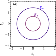
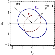
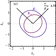
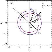
In the dispersion curves shown above, the first corresponds(panel (a)) to the simple Rashba system(=0) and the rest three figures corresponds to the three different cases, namely for , , respectively. The qualitative plot shows the asymmetric Fermi energy surfaces in the - plane. Note that when = (Fig.(b)) the curves touch each other along particular direction in k-space. This implies that for waves propagating along this direction spin splitting vanishes, and as a consequence precession induced spin dephasing ceases to act. This property was used in the non-ballistic spin field effect transistor proposed by Loss. For (panel (c) and panel(d)), the two Fermi surface becomes anisotropic in - plane. Therefore simultaneous presence of both Rashba and Dresselhaus spin orbit coupling provides a much better control over the spin splitting and we will see later that this leads to interesting phenomena for spin dependent elastic reflection from impenetrable barriers.
2.1 Elastic spin dependent scattering from impenetrable barrier
We consider two dimensional system in xy plane with an impenetrable barrier V(x) along axis,which is described by the Hamiltonian,
| (6) |
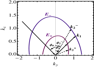
where is defined in E.1. We assume that V(x)=0 for x0 and V(x)= for x0 and along axis systems is free. Consider an electron beam with chirality and wave vector ( incident on impenetrable barrier at an angle . It is reflected elastically from the barrier and due to splitting of dispersion curves this processes generates two reflected waves, namely, ordinary reflected wave and extraordinary reflected wave. For ordinary reflection, energy as well momentum both are conserved while for extraordinary wave only energy is conserved. This is shown schematically in Fig.(2).
.
The wave vectors for incident, ordinarily(momentum preserving) and extraordinary reflected waves are with , and respectively. The most general scattering wave function for this system is the linear combination of these three and can be written as,following Ref.(),
Translational invariance parallel to the barrier at implie that y-component of crystal momentum is conserved, hence,
| (7) |
from which one obtains the angle of reflection for ordinary() and extraordinary beams ()as,
| (8) | |||
| (9) |
In general and are different, implying that a single incident wave with a particularly chirality generate waves of both chirality as is shown in Fig.(2). The ordinary reflected wave is always propagating while the extraordinary wave may be propagating or evanescent depending on whether is real or imaginary. Since has always a real value for but in case of a real solution exits only for after which this angle becomes complex, where
| (10) |
The splitting angle i.e. the angular difference between the two reflected beam is
| (11) |
The angle and have their largest value given by
| (12) |
obtained at and respectively. The splitting angle is positive while is negative From the conservation of , it can be seen that the and become functions of and respectively. When , becomes imaginary and leads to exponentially decaying current. At the interface, the wave function must be continuous which yields the conditions
| (13) |
| (14) |
Using the above equation it is straight forward to obtain ordinary () and extraordinary () reflection coefficients,
| (15) |
| (16) |
In the above expressions (13,14,15,16), the terms in curly brackets reduces to one for which agrees with the previous result of Ref.. In general the dependence on , is more complicated as is clear from the above expressions.To obtain insight and compare it with the simple Rashba system we plot reflection coefficient as a function of incident angles in Fig. (3) for the three different cases i.e. , .

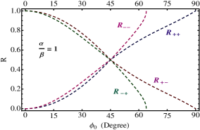
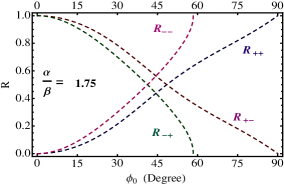
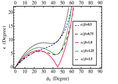
From Fig.(3) we notice that when the strength of Rashba and Dresselhaus SOC are different, the four reflection coefficients are never equal at any incident angle. This is consistent with the anisotropic Fermi contours in Fig(1) (panel(c) and (panel(d)). For at 45 degrees all four reflection coefficients become equal since at this point the two Fermi contours cross each other. The is again reflected in the splitting angle which is plotted in Fig.(4), again the splitting vanishes for at 45 degrees and for all other cases it never vanishes. We stress that this vanishing of splitting angle or crossing of Fermi contours happens only if both Rashba and Dresselhaus couplings are present and of equal strength. If only Rashba or only Dressehaus coupling is present this is not so. In fact this is related to the fact that simultaneous presence of Rashba and Dressehaus coupling of equal strength introduces a This implies that at a particular angle of incident the reflection from impenetrable barrier would not produce spin polarization only for case and in this atypical case only the boundary spin accumulation will be fully determined by the bulk spin currents. However in quasi one dimensional systems (finite transverse width) since the electrons will be approaching boundary from all possible incident angles, therefore the boundary spin accumulation in general will be determined by both bulk spin current as well by the reflection from the boundary.
3 Velocity and current
We calculate the expression for the velocity Operator from the Hamiltonian (1) and is given by :
| (17) |
While considering the real angles the magnitude v of the velocity :
| (18) |
We see here that for real angles the velocity is same for all the beams but the velocity will be slightly higher for the complex angle .We do not here give the lengthy expression. Also the probability current calculation gives :
| (19) | |||||
As expected, for an impenetrable barrier in both the cases of incoming and reflected beam while , for the region in which both the components of beam are present, oscillates as a function of distance from the barrier.It can be realized by considering the interference terms of the three components of the wave function. For the real angles, we get
| (20) | |||||
| (21) | |||||
| (22) | |||||
In over-critical region i.e. for the complex angle :
| (23) | |||||
the current decays exponentially as the distance increases from the barrier.

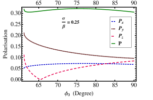
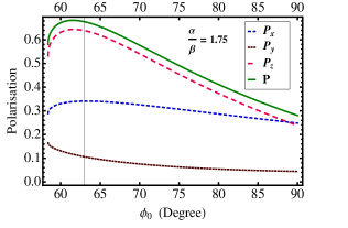
Figure (5) shows the net polarization (which is the addition of polarization of ordinary and extra-ordinary reflected beams) at different Rashba and Dresselhaus SOC strength, against the incident angle. The plot at different SOC strength is shown from which it is clear that net Polarization is non-zero at all the values of incident angle except at 45 degrees.

We calculate the net polarization which is plotted against the distance r from the barrier which is shown in figure (6). In this plot, value of Rashba SOC strength is taken to be equal to the Dresselhaus SOC strength . The contribution to this polarization is because of the two terms. In the first is term we have individually calculated and then added up the polarization for the incident, ordinarily and extraordinarily reflected beam. In the second term, polarization is calculated for the interference terms of these three components of the beam.The value of net polarization is always non-zero at all the values of the incident angle except at 45 degrees and oscillates with two different frequencies.

In the figure(7), for the over-critical region it is clearly shown that all the three components of polarization of extraordinary reflected beam will be present irrespective of the three cases of SOC strengths , and . Also in this region the net polarization always has non-zero values. All the three components of polarization as well as the net polarization will exponentially decay as the distance from
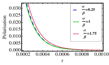
the barrier increases. This is shown in figure(8). This non-propagating non-zero polarization gives rise to spin-accumulation near the barrier which is clearly an important consequence of spin-dependent elastic reflection from a impenetrable barrier in the presence of R and D SOC. So it is clear that spin-accumulation near the barrier is a typical phenomena in which spin-accumulation near the barrier will not only depend upon the bulk spin-current but also on the spin-dependent scattering from the lateral impenetrable barrier which can be think of the lateral edges of the sample.
4 Conclusion
In conclusion, present work shows that the spin-orientation of the electrons changes because of the spin-dependent reflection from an impenetrable barrier in the presence Rashba and Dresselhaus SOC. It gives rise to a new mechanism of multiple reflection analogous to the birefringence phenomena. Also an important feature of anisotropy in the Fermi energy surface come into appearance because of this reflection. We also observed that increase in the value of Dresselhaus SOC strength gives increases the anisotropy in the system. In this case a non-zero spin-polarized current is observed for all incident angle between 0 to except at angle of which is clearly an another important feature of Rashba and Dresselhaus SOC interplay. Also it is shown that in the over-critical region,there is some spin-accumulation near the barrier is also affected by scattering of the bulk spin-current from the lateral edges of the sample which in turns affect the spin-accumulation as in the case of spin-hall effect.
References
- (1) S.Datta and B.Das, Appl.Phys.Lett. 56,(1990) 665.
- (2) Y.A.Bychkov and E.I.Rashba, J.Phys.C 17,(1984) 6039.
- (3) G.Dresselhaus, Phys.Rev. 100,(1955) 580.
- (4) V.Teodorescu and R.Winkler, Phys.Rev.B 80,(2009) 041311(R).
- (5) Y. K. Kato, R. C. Myers, A. C. Gossard, and D. D. Awschalom, Science 306, 1910 (2004).
- (6) V. Sih, R. C. Myers, Y. K. Kato, W. H. Lau, A. C. Gossard, and D. D. Awschalom, Nat. Phys. 1, 31 (2005).
- (7) J. Wunderlich, B. Kaestner, J. Sinova, and T. Jungwirth, Phys. Rev. Lett. 94, 047204 (2005).
- (8) M. I. Dyakonov and V. I. Perel, Phys. Lett. A 35, 459 (1971).
- (9) J. E. Hirsch, Phys. Rev. Lett. 83, 1834 (1999).
- (10) S. Zhang, Phys. Rev. Lett. 85, 393 (2000).
- (11) S. Murakami, N. Nagaosa, and S.-C. Zhang, Science 301, 1348 (2003).
- (12) J. Sinova, D. Culcer, Q. Niu, N. A. Sinitsyn, T. Jungwirth, and A. H. MacDonald, Phys. Rev. Lett. 92, 126603 (2004).
- (13) S.M.Badalyan and J.Fabian, Phys. Rev. Lett. 105, 186601 (2010).
- (14) T.P.Pareek, Phys. Rev. Lett. 92, 076601 (2004).
- (15) N. A. Sinitsyn, J. Phys:Condens. Matter 20, 3201(2008).
- (16) R.Winkler, Spin-Orbit Coupling Effects in Two-Dimensional Electron and Hole Systems (Springer, Berlin 2003).